EP1207078A2 - Couvercle et/ou dispositif séparateur pour le compartiment de charge ou de bagages d'un véhicule - Google Patents
Couvercle et/ou dispositif séparateur pour le compartiment de charge ou de bagages d'un véhicule Download PDFInfo
- Publication number
- EP1207078A2 EP1207078A2 EP01127125A EP01127125A EP1207078A2 EP 1207078 A2 EP1207078 A2 EP 1207078A2 EP 01127125 A EP01127125 A EP 01127125A EP 01127125 A EP01127125 A EP 01127125A EP 1207078 A2 EP1207078 A2 EP 1207078A2
- Authority
- EP
- European Patent Office
- Prior art keywords
- loading space
- separating device
- arm
- covering
- seat back
- Prior art date
- Legal status (The legal status is an assumption and is not a legal conclusion. Google has not performed a legal analysis and makes no representation as to the accuracy of the status listed.)
- Granted
Links
Images


Classifications
-
- B—PERFORMING OPERATIONS; TRANSPORTING
- B60—VEHICLES IN GENERAL
- B60R—VEHICLES, VEHICLE FITTINGS, OR VEHICLE PARTS, NOT OTHERWISE PROVIDED FOR
- B60R5/00—Compartments within vehicle body primarily intended or sufficiently spacious for trunks, suit-cases, or the like
- B60R5/04—Compartments within vehicle body primarily intended or sufficiently spacious for trunks, suit-cases, or the like arranged at rear of vehicle
- B60R5/044—Compartments within vehicle body primarily intended or sufficiently spacious for trunks, suit-cases, or the like arranged at rear of vehicle luggage covering means, e.g. parcel shelves
- B60R5/045—Compartments within vehicle body primarily intended or sufficiently spacious for trunks, suit-cases, or the like arranged at rear of vehicle luggage covering means, e.g. parcel shelves collapsible or transformable
- B60R5/047—Compartments within vehicle body primarily intended or sufficiently spacious for trunks, suit-cases, or the like arranged at rear of vehicle luggage covering means, e.g. parcel shelves collapsible or transformable collapsible by rolling-up
Definitions
- the invention relates to a loading space covering and / or loading space separation device for the loading or luggage compartment of a vehicle, e.g. one Combined motor vehicle or the like, according to claim 1.
- a loading space covering and / or loading space separation device for the loading or luggage compartment of a vehicle, e.g. one Combined motor vehicle or the like, according to claim 1.
- Such Load space covering and / or separating device is, for example, in DE 43 36 380 C2.
- the known device according to DE 43 36 380 C2 has as a holder a roller blind housing, which is a material web opposite the restoring torque of a spring motor can be unrolled from a winding shaft Network path contains.
- the inside edge of the web is on the winding shaft attached and the free end edge area of the mesh is with a handrail provided, the mushroom-like two holding ends in pocket-shaped Detachable form-fitting receptacles underneath the vehicle roof are held.
- roller blind housing according to DE 43 36 380 C2 is not in detail shown attached to the back of the rear seat back of a rear row of seats (see DE 43 36 380 C2 column 3 lines 52-56).
- a holder (roller blind housing) according to the DE 43 36 380 C2 designated genus, such as in DE 44 38 910 C1 described, in addition to a vertically stretchable network path also a horizontal stretchable material web in a separate material store, such as e.g. on a winding shaft.
- the network path forms a restraint or separator and the horizontally clamped Material web, e.g. in the form of a roller blind, a loading space cover.
- the rear seating group has three Seating for a continuous bench seat or for a single seat and a double seat.
- the seat back is accordingly 1/3: 2/3 divided.
- the 1/3 seat back is a single seat on the edge or one single seat on the edge, while the double seat back is assigned to the two other remaining seating areas, either one in total Seat or a double seat, is assigned.
- Both the 1/3 seat back and the 2/3 seat back are swivel lockable arranged.
- the holder (roller blind housing) is only on the back the 2/3 seat back can be detached using approximately dovetail-shaped fasteners held. So if the device according to DE 43 36 380 C2 Both seat backrests must be removed from the vehicle swiveled at the front and the mounting bracket (roller blind housing) transversely to the direction of travel shifted out of the dovetail shape and can be removed from the side through an open rear vehicle door.
- the device according to DE 43 36 380 C2 still allows the possibility of not being attached to the mounting bracket (blind housing) Fold the 1/3 seat back forward in the case of a longer load, whereby the Netzbahn can remain in its stretched state. Besides, it is possible with the known device, - expediently after rolling in the net - The 2/3 seat back including the mounting bracket attached to it together with the 1/3 seat back in the direction of travel if necessary to pan.
- the invention Based on the subject of DE 43 36 380 C2, the invention the task of a loading space covering and / or loading space separating device to create which is essential in practical use more options than previously allowed.
- the holder is independent, at least predominantly independent of any swivel position on the backrest.
- the holder is on the respective arm-side attachment point at least one of the pivoting movement the seat back independent arm.
- This arm-side attachment point can, if necessary, essentially transversely to the seat back pivot axis moved across the latter and along the trajectory the arm-side attachment point is gradually or releasably locked become.
- both seat backrests for example the 1/3 and 2/3 seat backs to fold down while holding the cradle remains in its above-described initial operating position.
- the holder is additional a material web that can be stretched downwards from it (e.g. a holding net) having.
- the invention allows the fastening points on the arm side arranged mounting bracket with all folded forward To move the backrests across the backrest swivel axis. there the holder is in a particularly advantageous manner on the back Seat back surfaces.
- each arm-side attachment point formed approximately in the manner of a console on which the receiving bracket placed or in which the holder is inserted and releasably attach is.
- Such a console can have a U-shaped cross section Form support web on which with respect to the direction of movement of the Holding arms at the front and rear are connected by a fastening web.
- a preferred embodiment according to the invention is thereby characterized that the two end portions of the mounting bracket are each arranged in a console.
- Such an inventive The arrangement is basically with one arm, but better still with two Arms to realize.
- each console itself is made according to other features of the invention further developed in that each console has a U-shaped cross section extending between the two fastening webs, from the adjacent one End area of the support bracket, pioneering limiting web forms. In this way, each console is approximately pocket-shaped and Allows a secure fit of the holder, for example of a blind housing.
- each holding arm has an arm-side Attachment point.
- Such a motion coupling element can, for example, from of a coupling cross-piece connecting the two holding arms his.
- each holding arm is a swivel arm which can be pivoted about an axis of rotation.
- restraint for the hold of motor vehicles see DE 44 38 910 C1
- the separating plate is at its free end a holder for three material webs.
- each arm forms a telescopic arm.
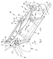
- a trunk or cargo space K a combination car imaginable, of whose body an interior Area R of a rear wheel arch trim, a C-pillar C and a horizontal one Strut B of a window F are indicated.
- the direction of travel of the motor vehicle is indicated by x.
- a rear seat arrangement 11 has a seat 12, a 2/3 seat back 13 and 1/3 seat back 14.
- the seat backs 13 and 14 are about a common seat back pivot axis S independently along the swivel arrow v can be folded down or along the swivel arrow u and at least in the upright position, not shown, can be pivoted. Shown in Fig. 1 is the forward (swivel arrow u) and downward position of both Backrests 13, 14.
- Each at the free end of two around a common axis of rotation D Swiveling holding arms 15 is a fastening point in the form of a holding arm an approximately pocket-like console 16 attached.
- Each console 16 has one approximately U-shaped cross-section, which of a support web 17, a front mounting web 18, a rear mounting web 19 and from a boundary web 20 facing outwards is limited.
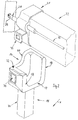
- the two brackets 16 are used for the positive reception of two End regions 21 of a receiving holder, here one with a total of 22 designated roller blind housing.
- the roller blind housing 22 can be one material web or several material webs contain. In the present case, there are one in the roller blind housing 22 Mesh that can be stretched vertically and one that can be stretched horizontally Cover roller blind each recorded on its own winding shaft. In addition, the roller blind housing, as indicated in FIGS. 4 and 5, on take up a pull-out mesh track on its own winding shaft.
- the network tracks themselves are not visible, but they are on the respective one free edge attached support rods 23 (Fig. 1) and 24 (Fig. 4 and 5) shown schematically.
- the provided on both sides on the handrails Stopping ends, e.g. the two holding ends 25 of the holding rod 23 can not in as shown in the interior of the combination motor vehicle, e.g. the stops 25 adjacent to the vehicle roof.
- the two swivel or holding arms 15 of the device 10 are by means of a coupling shaft 26 rotationally rigidly coupled to one another.
- Fig. 1 is the upright position on the one hand and on the other (dash-dotted) that folded forward and down according to the swivel part u Position of the two holding arms 15 shown.
- both the horizontally clamped Covering roller blind of which only the end board 27 is shown, as well as the network track with its handrail 23 (see also stopping ends 25) independently can be clamped from the pivot position of the holding arms 15 and on the vehicle side are releasably attached.
- Fig. 1 is the part-circular movement path E, along which the two consoles 16 are movable, indicated by dash-dotted lines (see analogously to this the dash-dotted lines labeled E in Figs. 4 and 5).
- the brackets 16 are gradual along the respective movement path E. releasably to lock what by means of linearly movable locking pin 28 des Roller blind housing 22 happens.
- the locking pins 28 act schematically in FIG. 2 shown bolt-side locking openings 29 together.
- the two Locking pin 28 are via an actuating linkage 30, which by means of a Push button 31 is operated, linearly drivable.
- releasable mounting of the end regions 21 of the roller blind housing 22 in the consoles 16 have the latter in the manner of belt buckles plug-in receptacles 32 formed by vehicle occupant seat belts, in which plug-in fastening tongues held at the end regions 21 of the roller blind housing 22 33 can intervene releasably.
- the buckle-like receptacles 32 can be unlocked using pushbuttons 34.
- the structure of a holding arm 15 can be seen from FIG. 3.
- the holding arm 15 has a rectangular profile section 35, in which a plug pin is located below 36 of a pivot block 37 and above a plug 38 of the console 16 intervention.
- the pivot bearing block 37 is with its bearing bore 39 on the bearing journal 40 of a bearing block 41 fastened on the vehicle side is axially pushed on.
- a flange 42 By means of a flange 42, the coupling shaft 26 is not shown bolts in threaded holes 43 of the pivot block 37th schraubbeanno.
- the plug pins 36, 38 can be released in a manner not shown or permanently attached to the rectangular profile section.
- a pivot lock of the holding arms 15 along the path of movement E is in addition to the locking pin arrangement 28, 29 or alternatively to the latter in principle also possible in a stepwise manner in a manner not shown or stepless locking means between the journal 40 and the Pivot bearing blocks 37 is provided.
- any peculiarities of each individual Use case can be a detachable connection of the pivotable arrangement 15, 15, 22 of the device 10 to a seat back or to both seat backs 13, 14 be appropriate.
- Such a releasable connection can e.g. just because of that be useful to get rattling noises when folded down Arrangement 15, 15, 22 (see FIG. 1) to be avoided.
- the roller blind housing 22 (see FIG. 7) has a pawl or Lock trap 43, which is to be operated by means of a push button 44 and which with a locking recess, not shown (e.g. one anyway existing seat back lock), for example on the back of the back 45, 46 cooperates.
- a pawl or Lock trap 43 which is to be operated by means of a push button 44 and which with a locking recess, not shown (e.g. one anyway existing seat back lock), for example on the back of the back 45, 46 cooperates.
- the holding arms 15 designed in the manner of a telescopic rail or a telescopic tube.
- a telescopic outer tube 47 of rectangular cross section is a telescopic inner tube 48, which also has a rectangular cross section, with sliding seat slidably added along the movement path E.
- the consoles 16 in FIGS. 4-6 correspond to the illustrations in FIG. 1-3.
- the roller blind housing 22 also corresponds to the illustrations in FIGS. 1-3 in conjunction with the illustration in FIG. 7.
- FIG. 4 (cf. also solid representation according to FIG Fig. 6) in its starting position immediately behind the seat backs, not shown 13, 14 positioned.
- both the upper Holding net with the holding rod 23 and the lower holding net with the holding rod 24 clamped and detachably fastened inside the vehicle.
- tilt bearing 49 i.e. to unlock so that front areas 50 of the telescopic inner tubes 48 according to the Dashed line representation in FIG. 5 along circular movement paths E. can be folded down and locked in a manner not shown, whereby it is sufficient to secure the load completely, only the upper one To stretch the web with its support rod 23 upwards.
- roller blind housing 22 which also functions as a crossbar fills.
- a crossbar 51 is drawn with dashed lines, which in addition or instead of the coupling shaft 26, a movement coupling element can form.
Landscapes
- Engineering & Computer Science (AREA)
- Mechanical Engineering (AREA)
- Vehicle Step Arrangements And Article Storage (AREA)
- Seats For Vehicles (AREA)
Applications Claiming Priority (2)
| Application Number | Priority Date | Filing Date | Title |
|---|---|---|---|
| DE2000157572 DE10057572C2 (de) | 2000-11-20 | 2000-11-20 | Laderaum-Abdeck- und/oder Laderaum-Trennvorrichtung für den Lade-oder Gepäckraum eines Fahrzeugs |
| DE10057572 | 2000-11-20 |
Publications (3)
| Publication Number | Publication Date |
|---|---|
| EP1207078A2 true EP1207078A2 (fr) | 2002-05-22 |
| EP1207078A3 EP1207078A3 (fr) | 2004-06-16 |
| EP1207078B1 EP1207078B1 (fr) | 2007-01-10 |
Family
ID=7663999
Family Applications (1)
| Application Number | Title | Priority Date | Filing Date |
|---|---|---|---|
| EP20010127125 Expired - Lifetime EP1207078B1 (fr) | 2000-11-20 | 2001-11-15 | Couvercle et/ou dispositif séparateur pour le compartiment de charge ou de bagages d'un véhicule |
Country Status (2)
| Country | Link |
|---|---|
| EP (1) | EP1207078B1 (fr) |
| DE (2) | DE10057572C2 (fr) |
Cited By (4)
| Publication number | Priority date | Publication date | Assignee | Title |
|---|---|---|---|---|
| EP1283130A3 (fr) * | 2001-08-07 | 2004-01-14 | BOS GmbH & Co. KG | Dispositif de protection pour le compartiment bagages d'un véhicule |
| CN102947138A (zh) * | 2010-04-07 | 2013-02-27 | 宝适汽车部件(太仓)有限公司 | 用于车辆内部空间的保护装置 |
| FR2992599A1 (fr) * | 2012-06-27 | 2014-01-03 | Renault Sa | Vehicule a compartiment a bagages dote d'un tendelet escamotable motorise |
| FR2992598A1 (fr) * | 2012-06-27 | 2014-01-03 | Renault Sa | Vehicule a compartiment a bagages dote d'un tendelet escamotable equilibre par cables |
Families Citing this family (6)
| Publication number | Priority date | Publication date | Assignee | Title |
|---|---|---|---|---|
| DE10223682B4 (de) * | 2002-05-22 | 2005-12-01 | Bos Gmbh & Co. Kg | Schutzvorrichtung für einen Laderaum eines Kraftfahrzeugs |
| DE10320527B3 (de) | 2003-04-30 | 2004-12-09 | Bos Gmbh & Co. Kg | Trennvorrichtung für einen Fahrzeuginnenraum |
| DE10326024B3 (de) * | 2003-06-02 | 2004-12-09 | Bos Gmbh & Co. Kg | Halterung für eine Funktionseinrichtung in einem Fahrzeuginnenraum |
| DE102004009520A1 (de) * | 2003-11-26 | 2005-06-30 | Hörmann Kg Dissen | Windlast-Stützvorrichtung sowie damit versehener Rollabschluss |
| DE102007005185B3 (de) * | 2007-01-29 | 2008-04-10 | Mp Solution Gmbh | Laderaumabdeckung |
| DE102008036005A1 (de) | 2008-08-01 | 2010-02-04 | Bayerische Motoren Werke Aktiengesellschaft | Kraftfahrzeug |
Citations (3)
| Publication number | Priority date | Publication date | Assignee | Title |
|---|---|---|---|---|
| DE4336380C2 (de) | 1993-10-25 | 1995-08-10 | Baumeister & Ostler Gmbh Co | Sicherheitsnetzanordnung |
| DE4438910C1 (de) | 1994-11-03 | 1996-03-21 | Butz Peter Verwaltung | Rückhaltevorrichtung für den Laderaum von Kraftfahrzeugen, wie z. B. für Kombinationskraftwagen oder Großraum-Personenkraftwagen |
| EP0909679A2 (fr) | 1997-10-17 | 1999-04-21 | PETER BUTZ GmbH & Co Verwaltungs-KG | Couvercle pour le compartiment à baggages, rideau écran ou similaire pour le compartiment à baggages ou coffre d'un véhicule |
Family Cites Families (5)
| Publication number | Priority date | Publication date | Assignee | Title |
|---|---|---|---|---|
| DE4123655A1 (de) * | 1991-07-17 | 1993-01-21 | Bayerische Motoren Werke Ag | Kraftfahrzeug, insbesondere kombifahrzeug, mit mindestens einem sitz |
| DE19605907B4 (de) * | 1996-02-17 | 2005-11-03 | Bos Gmbh & Co. Kg | Sicherungsvorrichtung für einen Innenraum eines Kraftfahrzeugs |
| SE508854C2 (sv) * | 1997-03-27 | 1998-11-09 | Volvo Ab | Förstärkningsanordning för fordon |
| JP2001010409A (ja) * | 1999-06-30 | 2001-01-16 | Kanto Auto Works Ltd | 自動車のトノカバー |
| FR2810935B1 (fr) * | 2000-07-03 | 2002-08-30 | Cera | Dispositif de retenue de bagages pour vehicule automobile |
-
2000
- 2000-11-20 DE DE2000157572 patent/DE10057572C2/de not_active Expired - Fee Related
-
2001
- 2001-11-15 EP EP20010127125 patent/EP1207078B1/fr not_active Expired - Lifetime
- 2001-11-15 DE DE50111844T patent/DE50111844D1/de not_active Expired - Lifetime
Patent Citations (3)
| Publication number | Priority date | Publication date | Assignee | Title |
|---|---|---|---|---|
| DE4336380C2 (de) | 1993-10-25 | 1995-08-10 | Baumeister & Ostler Gmbh Co | Sicherheitsnetzanordnung |
| DE4438910C1 (de) | 1994-11-03 | 1996-03-21 | Butz Peter Verwaltung | Rückhaltevorrichtung für den Laderaum von Kraftfahrzeugen, wie z. B. für Kombinationskraftwagen oder Großraum-Personenkraftwagen |
| EP0909679A2 (fr) | 1997-10-17 | 1999-04-21 | PETER BUTZ GmbH & Co Verwaltungs-KG | Couvercle pour le compartiment à baggages, rideau écran ou similaire pour le compartiment à baggages ou coffre d'un véhicule |
Cited By (6)
| Publication number | Priority date | Publication date | Assignee | Title |
|---|---|---|---|---|
| EP1283130A3 (fr) * | 2001-08-07 | 2004-01-14 | BOS GmbH & Co. KG | Dispositif de protection pour le compartiment bagages d'un véhicule |
| US6843518B2 (en) | 2001-08-07 | 2005-01-18 | Bos Gmbh & Co. Kg | Protective device for a luggage area of a vehicle |
| CN102947138A (zh) * | 2010-04-07 | 2013-02-27 | 宝适汽车部件(太仓)有限公司 | 用于车辆内部空间的保护装置 |
| CN102947138B (zh) * | 2010-04-07 | 2016-03-02 | 宝适汽车部件(太仓)有限公司 | 用于车辆内部空间的保护装置 |
| FR2992599A1 (fr) * | 2012-06-27 | 2014-01-03 | Renault Sa | Vehicule a compartiment a bagages dote d'un tendelet escamotable motorise |
| FR2992598A1 (fr) * | 2012-06-27 | 2014-01-03 | Renault Sa | Vehicule a compartiment a bagages dote d'un tendelet escamotable equilibre par cables |
Also Published As
| Publication number | Publication date |
|---|---|
| EP1207078B1 (fr) | 2007-01-10 |
| DE10057572A1 (de) | 2002-06-06 |
| DE50111844D1 (de) | 2007-02-22 |
| EP1207078A3 (fr) | 2004-06-16 |
| DE10057572C2 (de) | 2002-11-14 |
Similar Documents
| Publication | Publication Date | Title |
|---|---|---|
| EP1283130B1 (fr) | Dispositif de protection pour le compartiment bagages d'un véhicule | |
| DE102011002656B4 (de) | Verstellbare Speicher-Führungsvorrichtung | |
| DE10345181B4 (de) | Fahrzeugsitzanordnung | |
| DE102008060747B4 (de) | Bedarfsitz für ein Kraftfahrzeug | |
| EP0909679B1 (fr) | Couvercle pour le compartiment à baggages, rideau écran ou similaire pour le compartiment à baggages ou coffre d'un véhicule | |
| DE29810333U1 (de) | Sitzmodul | |
| EP1329355A1 (fr) | Siège modulaire | |
| DE2145022C2 (de) | Sicherheitsgurtsystem für ein Kraftfahrzeug | |
| DE10057572C2 (de) | Laderaum-Abdeck- und/oder Laderaum-Trennvorrichtung für den Lade-oder Gepäckraum eines Fahrzeugs | |
| DE10261393A1 (de) | Höhenverstellbares Laderaumbodensystem | |
| EP3938240B1 (fr) | Dispositif repose-jambes pour un siège de véhicule et siège de véhicule | |
| DE4416456C1 (de) | Vorrichtung zur schutzweisen Abtrennung des Raumes hinter dem Vorder- oder Hintersitz eines Personenkraftfahrzeugs | |
| DE102005036805B4 (de) | Laderaumabtrennung | |
| DE20019704U1 (de) | Laderaum-Abdeck- und/oder Laderaum-Trennvorrichtung für den Lade- oder Gepäckraum eines Fahrzeuges | |
| DE69814570T2 (de) | Anordnung für einen ausnehmbaren und in Längsrichtung verstellbaren Sitz im Innenraum eines Kraftfahrzeuges | |
| EP1749698A2 (fr) | Couvercle pour le compartiment à bagages | |
| DE102010042881B4 (de) | Fahrzeugsitz mit einer Sitztiefenverstelleinrichtung | |
| DE102009033802A1 (de) | Sitzanlage für einen Innenraum eines Kraftwagens | |
| DE69818616T2 (de) | Anordnung für einen ausnehmbaren und in Längsrichtung verstellbaren Sitz im Innenraum eines Kraftfahrzeuges | |
| EP3109093B1 (fr) | Véhicule agricole | |
| DE102023002806A1 (de) | Unterteilungseinrichtung für einen Innenraum eines Kraftwagens | |
| DE102018215733A1 (de) | Sitzbank eines Fahrzeugs und Fahrzeug | |
| DE19509159A1 (de) | Kopfstützenanordnung | |
| DE10204664B4 (de) | Kraftfahrzeug mit einem durch eine Trennanordnung unterteilbaren Innenraum | |
| EP4396035A1 (fr) | Ensemble siège, véhicule et procédé d'installation utilisant une pièce supplémentaire pour fixer un autre composant dans l'habitacle du véhicule |
Legal Events
| Date | Code | Title | Description |
|---|---|---|---|
| PUAI | Public reference made under article 153(3) epc to a published international application that has entered the european phase |
Free format text: ORIGINAL CODE: 0009012 |
|
| AX | Request for extension of the european patent |
Free format text: AL;LT;LV;MK;RO;SI |
|
| RAP1 | Party data changed (applicant data changed or rights of an application transferred) |
Owner name: BOS GMBH & CO. KG |
|
| PUAL | Search report despatched |
Free format text: ORIGINAL CODE: 0009013 |
|
| AK | Designated contracting states |
Kind code of ref document: A3 Designated state(s): AT BE CH CY DE DK ES FI FR GB GR IE IT LI LU MC NL PT SE TR |
|
| AX | Request for extension of the european patent |
Extension state: AL LT LV MK RO SI |
|
| 17P | Request for examination filed |
Effective date: 20041005 |
|
| AKX | Designation fees paid |
Designated state(s): DE FR GB IT SE |
|
| RAP1 | Party data changed (applicant data changed or rights of an application transferred) |
Owner name: BOS GMBH & CO. KG Owner name: AUDI AG |
|
| GRAP | Despatch of communication of intention to grant a patent |
Free format text: ORIGINAL CODE: EPIDOSNIGR1 |
|
| GRAS | Grant fee paid |
Free format text: ORIGINAL CODE: EPIDOSNIGR3 |
|
| GRAA | (expected) grant |
Free format text: ORIGINAL CODE: 0009210 |
|
| AK | Designated contracting states |
Kind code of ref document: B1 Designated state(s): DE FR GB IT SE |
|
| REG | Reference to a national code |
Ref country code: GB Ref legal event code: FG4D Free format text: NOT ENGLISH |
|
| RIN1 | Information on inventor provided before grant (corrected) |
Inventor name: FABER, WOLFGANG Inventor name: CRISP, TERENCE SAM Inventor name: HOETTER, WOLFGANG Inventor name: SITZLER, WOLFGANG |
|
| REF | Corresponds to: |
Ref document number: 50111844 Country of ref document: DE Date of ref document: 20070222 Kind code of ref document: P |
|
| REG | Reference to a national code |
Ref country code: SE Ref legal event code: TRGR |
|
| GBT | Gb: translation of ep patent filed (gb section 77(6)(a)/1977) |
Effective date: 20070413 |
|
| ET | Fr: translation filed | ||
| PLBE | No opposition filed within time limit |
Free format text: ORIGINAL CODE: 0009261 |
|
| STAA | Information on the status of an ep patent application or granted ep patent |
Free format text: STATUS: NO OPPOSITION FILED WITHIN TIME LIMIT |
|
| 26N | No opposition filed |
Effective date: 20071011 |
|
| PGFP | Annual fee paid to national office [announced via postgrant information from national office to epo] |
Ref country code: IT Payment date: 20071128 Year of fee payment: 7 |
|
| PGFP | Annual fee paid to national office [announced via postgrant information from national office to epo] |
Ref country code: SE Payment date: 20071126 Year of fee payment: 7 |
|
| PGFP | Annual fee paid to national office [announced via postgrant information from national office to epo] |
Ref country code: FR Payment date: 20071120 Year of fee payment: 10 Ref country code: GB Payment date: 20071123 Year of fee payment: 7 |
|
| REG | Reference to a national code |
Ref country code: FR Ref legal event code: ST Effective date: 20080930 |
|
| PG25 | Lapsed in a contracting state [announced via postgrant information from national office to epo] |
Ref country code: FR Free format text: LAPSE BECAUSE OF NON-PAYMENT OF DUE FEES Effective date: 20071130 |
|
| EUG | Se: european patent has lapsed | ||
| GBPC | Gb: european patent ceased through non-payment of renewal fee |
Effective date: 20081115 |
|
| PG25 | Lapsed in a contracting state [announced via postgrant information from national office to epo] |
Ref country code: IT Free format text: LAPSE BECAUSE OF NON-PAYMENT OF DUE FEES Effective date: 20081115 |
|
| PG25 | Lapsed in a contracting state [announced via postgrant information from national office to epo] |
Ref country code: GB Free format text: LAPSE BECAUSE OF NON-PAYMENT OF DUE FEES Effective date: 20081115 |
|
| PG25 | Lapsed in a contracting state [announced via postgrant information from national office to epo] |
Ref country code: SE Free format text: LAPSE BECAUSE OF NON-PAYMENT OF DUE FEES Effective date: 20081116 |
|
| PGFP | Annual fee paid to national office [announced via postgrant information from national office to epo] |
Ref country code: DE Payment date: 20141204 Year of fee payment: 14 |
|
| PG25 | Lapsed in a contracting state [announced via postgrant information from national office to epo] |
Ref country code: FR Free format text: LAPSE BECAUSE OF NON-PAYMENT OF DUE FEES Effective date: 20081130 |
|
| REG | Reference to a national code |
Ref country code: DE Ref legal event code: R119 Ref document number: 50111844 Country of ref document: DE |
|
| PG25 | Lapsed in a contracting state [announced via postgrant information from national office to epo] |
Ref country code: DE Free format text: LAPSE BECAUSE OF NON-PAYMENT OF DUE FEES Effective date: 20160601 |