EP1207417B1 - Unité de mesure corrigée en polarisation - Google Patents
Unité de mesure corrigée en polarisation Download PDFInfo
- Publication number
- EP1207417B1 EP1207417B1 EP01112440A EP01112440A EP1207417B1 EP 1207417 B1 EP1207417 B1 EP 1207417B1 EP 01112440 A EP01112440 A EP 01112440A EP 01112440 A EP01112440 A EP 01112440A EP 1207417 B1 EP1207417 B1 EP 1207417B1
- Authority
- EP
- European Patent Office
- Prior art keywords
- polarization
- optical
- output
- measuring unit
- beams
- Prior art date
- Legal status (The legal status is an assumption and is not a legal conclusion. Google has not performed a legal analysis and makes no representation as to the accuracy of the status listed.)
- Expired - Lifetime
Links
Images
Classifications
-
- G—PHYSICS
- G02—OPTICS
- G02B—OPTICAL ELEMENTS, SYSTEMS OR APPARATUS
- G02B27/00—Optical systems or apparatus not provided for by any of the groups G02B1/00 - G02B26/00, G02B30/00
- G02B27/28—Optical systems or apparatus not provided for by any of the groups G02B1/00 - G02B26/00, G02B30/00 for polarising
- G02B27/283—Optical systems or apparatus not provided for by any of the groups G02B1/00 - G02B26/00, G02B30/00 for polarising used for beam splitting or combining
Definitions
- the present invention relates to the conversion of the state of polarization of an optical beam in an optical measuring unit.
- the state of polarization of an optical beam represents an important feature in many applications, in particular when measurements comprise polarization dependent components.
- Polarizers are typically inserted into the optical beam in order to provide a defined state of polarization. While optical signals with defined state of polarization will pass the polarizer, optical signals with other states of polarization will generally be absorbed or reflected. Disadvantageous in that solution, however, is that the optical power of the output beam after the polarizer can be significantly decreased with respect to the input beam. Further, the optical power of the output beam becomes a function of the state of polarization of the input beam.
- a polarization converter for converting randomly polarized light to linearly polarized light is known from EP-A-431894.
- EP-A-782028 an apparatus produces parallel beams with like polarization by aid of a polarization splitter/combiner, and the parallel beams are then subject to polarization dependent processing.
- US-A-5,102,222 discloses a light wave polarization determination using a hybrid system. A polarimeter is described in US-A-6,043,887.
- US-A-6,075,647 discloses an optical spectrum analyzer eliminating polarization-dependent wavelength spreading.
- a polarization modifier spatially separates orthogonal polarization components and rotates the relative polarization components, so that the beams are incident on a tunable interference filter in a multipass configuration at a single polarization state.
- the returning beams are detected by a power meter.
- WO-A-01/13079 discloses a polarizing spectrograph, wherein the input beam is split into p and s polarized components, which are each dispersed by a prism to form separate spectra for each polarization p and s.
- the teaching of that document forms the preamble of claim 1.
- the object is solved by the independent claims. Preferred embodiments are shown by the dependent claims.
- a polarization converter comprises a polarization dependent beam splitter splitting up an incoming optical beam into a first and a second beam, each with a defined state of polarization but different from each other.
- one of the beams will be polarized horizontally while the other beam will be polarized vertically.
- a polarization adapter is provided to the second beam of the polarization dependent beam splitter. The polarization adapter converts the state of polarization from its input to its output in a way that the states of polarization of the first beam (from the polarization d ependent s plitter) a nd t he o utput beam from the polarization adapter substantially match.
- Each one of the two beams with substantially matching states of polarization might then optionally be provided to a polarizer with substantially the same intended state of polarization, in order to correct small deviations in the states of polarization. It goes without saying that the polarization orientation of the polarizer should match with the states of polarization of its input beams in order to reduce unwanted power consumption by the polarizer.
- the polarization converter according to the present invention thus provides a first output beam (as the first beam from the polarization dependent beam splitter) and a second output beam (as the output from the polarization adapter with the second beam of the polarization dependent beam splitter as input thereof).
- the two output beams of the polarization converter are provided with substantially the same defined state of polarization.
- the sum of power of the two output beams of the polarization converter substantially equals the optical power of the input beam to the polarization converter.
- the two beams are spatially separated from each other.
- the two output beams from the polarization converter are provided substantially in parallel and preferably with only a small distance between the two parallel output beams.
- the area of further optical components subjected to the two output beams from the polarization converter is designed to be sufficiently large, so that the same optical component(s) can be applied for both output beams of the polarization converter.
- the polarization adapter preferably comprises a ⁇ /2-plate which rotates the linear polarization by 90 degrees (and e.g. converts from parallel to perpendicular polarization).
- the optical power of the input is further detected in order to monitor a variation of the input power to the polarization converter.
- the detected input power can be used for power control purposes or to correct parasitic effects of the set-up, e.g. to calibrate the arrangement in terms of wavelength dependency of the detector response or the total set-up. This allows achieving highest absolute power measurement accuracy.
- Additional electrical circuits as well as some signal processing and related software functionality can be provided, dependent on the specific application, e.g. in order to process the signals of the detected photo currents.
- the invention can be partly supported by one or more suitable software programs, which can be stored on or otherwise provided by any kind of data carrier, and which might be executed in or by any suitable data processing unit.
- Such software programs is preferably used to proved algorithms for deriving the absolute power and wavelength information out of the individual detector signals and the calibration data
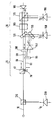
- an optical input beam 10 is launched through a polarization converter 20 e.g. to a polarization dependent analysis unit 30.
- the polarization converter 20 comprises a polarization dependent beam splitter 40 receiving the input beam 10 and dividing the input beam 10 in a first beam 50 with a horizontal polarization and a second beam 60 with a vertical polarization.
- Arrows indicate the states of polarization, whereby the selected states of polarization in Fig. 1 only represent examples.
- the second output beam 60 is preferably redirected e.g. by a mirror 70 in a way that the first and second beams 50 and 60 are substantially parallel to each other. However, both beams 50 and 60 remain spatially separated from each other to avoid interference.
- the second beam 60 is provided to a ⁇ /2-plate 80 acting as a polarization adapter (here: polarization rotator) in order to change the second beam 60 with the vertical state of polarization into a beam 90 having a horizontal state of polarization as the first output beam 50.
- a polarization adapter here: polarization rotator
- the beams 50 and 90 substantially match in their state of polarization and orientation (here: horizontal polarization).
- the output beams 50 and 90 are preferably directed to a polarizer 100.
- the polarizer 100 is a horizontal polarizer. This is optional and reduces the need for high accurate alignment of the ⁇ /2-plate 80 in terms of rotation.
- the beams 50 and 90 (with or without the optional polarizer 100) provide the outputs of the polarization converter 20 and can be launched to the polarization dependent analysis unit 30.
- the sum of power of both output beams 50 and 90 is substantially equal to the optical power of the input beam 10.
- the polarization dependent analysis unit 30 is preferably provided in a way that the two output beams 50 and 90 can be processed together without requiring additional or separated components for each path. This can be preferably achieved in that components subjected to the parallel output beams 50 and 90 are provided with sufficiently large areas to cover both output beams 50 and 90.
- the polarization dependent analysis unit 30 is a wavemeter for determining the wavelength of the input beam 10.
- the wavemeter 30 comprises an interferometric wavelength determination unit as disclosed in detail in EP-A-875743 by the same applicant, requiring a defined state of polarization.
- the wavemeter 30 comprises a beam splitter 120 dividing the output beams 50 and 90 from the polarization converter 20 into beams directed towards a coarse measuring unit comprised of a beam splitter 130 having a wavelength dependent reflection and transmission characteristic.
- the two beams reflected by the beam splitter 130 are detected by a detector 140, while a detector 150 detects the two beams transmitted through the beam splitter 130.
- the detectors 140 and 140 together with a (not shown) coarse analyses unit are also part of the coarse measuring unit.
- the other two beams passing through the beam splitter 120 are directed to a ⁇ /8-plate 160, which requires a defined state of polarization.
- the output thereof is provided to a polarization splitter 170, and detectors 180 and 190 detect the beams derived from the polarization splitter 170.
- the input beam of the ⁇ /8-plate 160 should be highly linear polarized to achieve high wavelength accuracy.
- an input power monitor 200 can further be coupled to the input beam 10, e.g. by means of a beam splitter 210, in order to precisely monitor the optical input power and to control deviations thereof. Besides this the monitor 200 could be used to correct for intrinsic loss in the polarization converter 20. This loss could be determined by the signal ratios from the monitor 200 with respect to the sum of the two monitors 140 and 150.
Landscapes
- Physics & Mathematics (AREA)
- General Physics & Mathematics (AREA)
- Optics & Photonics (AREA)
- Instruments For Measurement Of Length By Optical Means (AREA)
- Optical Communication System (AREA)
- Investigating Or Analysing Materials By Optical Means (AREA)
Claims (7)
- Une unité de mesure optique (20, 30) pour mesurer une propriété optique d'un faisceau optique entrant (10), qui comprend:dans laquelle le convertisseur de polarisation (20) comprend:un convertisseur (20) de polarisation apte à recevoir le faisceau optique entrant (10) et à émettre un premier faisceau de sortie (50) et un deuxième faisceau de sortie (90) de ce convertisseur, qui sont spatialement séparés et dont les états de polarisation sont sensiblement les mêmes, etune unité d'analyse (30) en fonction de la polarisation apte à recevoir le premier (50) et le deuxième (90) faisceaux de sortie du convertisseur (20) de polarisation, et à mesurer la propriété optique tant du premier (50) que du deuxième (90) faisceaux de sortie, en mesurant ainsi la propriété optique selon une dépendance réduite vis-à-vis de la polarisation,dans laquelle le premier faisceau de sortie (50) et le deuxième faisceau de sortie (90) sont spatialement séparés l'un de l'autre pour éviter des effets d'interférences,un diviseur (40) de faisceau en fonction de la polarisation apte à diviser un faisceau optique entrant (10) pour former le premier faisceau de sortie (50) du convertisseur (20) de polarisation et un deuxième faisceau de sortie (60), dont les états de polarisation sont définis pour chacun mais différents l'un de l'autre, etun adaptateur (80) de polarisation apte à recevoir le deuxième faisceau (60), pour transformer sa polarisation, et à émettre le deuxième faisceau de sortie (90) du convertisseur (20) de polarisation, d'une manière telle que l'état de polarisation du deuxième faisceau de sortie (90) est sensiblement le même que l'état de polarisation du premier faisceau de sortie (50),
caractérisée en ce que:une zone du détecteur (140, 150, 180, 190) de l'unité d'analyse (30) en fonction de la polarisation soumise au premier (50) et au deuxième (90) faisceaux de sortie du convertisseur de polarisation, ou à une partie de ceux-ci, est réalisée de manière à être suffisamment grande pour recevoir simultanément le premier (50) et le deuxième (90) faisceaux de sortie, ou la partie de ceux-ci. - L'unité de mesure optique (20, 30) selon la revendication 1, dans laquelle le premier faisceau de sortie (50) est polarisé horizontalement et le deuxième faisceau (60) est polarisé verticalement, ou vice-versa.
- L'unité de mesure optique (20, 30) selon la revendication 1 ou 2, dans laquelle l'adaptateur (80) de polarisation comprend une lame λ/2.
- L'unité de mesure optique (20, 30) selon l'une quelconque des revendications précédentes, qui comprend en outre un polariseur (100) apte à recevoir tant le premier (50) que le deuxième (90) faisceaux de sortie et à corriger des écarts faibles entre les états de polarisation du premier (50) et du deuxième (90) faisceaux de sortie.
- L'unité de mesure optique (20, 30) selon l'une quelconque des revendications précédentes, qui comprend en outre un dispositif directeur (70) de faisceaux apte à amener le premier (50) et le deuxième (90) faisceaux de sortie à être sensiblement parallèles l'un à l'autre.
- L'unité de mesure optique (20, 30) selon l'une quelconque des revendications précédentes, qui comprend en outre une unité de surveillance (200) pour surveiller la puissance optique du faisceau optique entrant (10).
- L'unité de mesure optique (20, 30) selon l'une quelconque des revendications précédentes, dans laquelle l'unité de mesure optique est un ondemètre et le détecteur (140, 150, 180, 190) détecte la puissance optique des faisceaux reçus.
Priority Applications (3)
| Application Number | Priority Date | Filing Date | Title |
|---|---|---|---|
| DE60104629T DE60104629T2 (de) | 2001-05-22 | 2001-05-22 | Polarisationskorrigierte optische Messeinheit |
| EP01112440A EP1207417B1 (fr) | 2001-05-22 | 2001-05-22 | Unité de mesure corrigée en polarisation |
| US10/093,237 US6671046B2 (en) | 2001-05-22 | 2002-03-07 | Polarization converter |
Applications Claiming Priority (1)
| Application Number | Priority Date | Filing Date | Title |
|---|---|---|---|
| EP01112440A EP1207417B1 (fr) | 2001-05-22 | 2001-05-22 | Unité de mesure corrigée en polarisation |
Publications (2)
| Publication Number | Publication Date |
|---|---|
| EP1207417A1 EP1207417A1 (fr) | 2002-05-22 |
| EP1207417B1 true EP1207417B1 (fr) | 2004-08-04 |
Family
ID=8177504
Family Applications (1)
| Application Number | Title | Priority Date | Filing Date |
|---|---|---|---|
| EP01112440A Expired - Lifetime EP1207417B1 (fr) | 2001-05-22 | 2001-05-22 | Unité de mesure corrigée en polarisation |
Country Status (3)
| Country | Link |
|---|---|
| US (1) | US6671046B2 (fr) |
| EP (1) | EP1207417B1 (fr) |
| DE (1) | DE60104629T2 (fr) |
Families Citing this family (5)
| Publication number | Priority date | Publication date | Assignee | Title |
|---|---|---|---|---|
| DE10321102A1 (de) * | 2003-05-09 | 2004-12-02 | Hentze-Lissotschenko Patentverwaltungs Gmbh & Co.Kg | Aufteilungsvorrichtung für Lichtstrahlen |
| US8760653B2 (en) * | 2009-10-19 | 2014-06-24 | Ipg Photonics Corporation | Assembly for monitoring power of randomly polarized light |
| US10072971B2 (en) * | 2010-04-16 | 2018-09-11 | Metal Improvement Company, Llc | Flexible beam delivery system for high power laser systems |
| US8922773B2 (en) * | 2011-12-29 | 2014-12-30 | Rudolph Research Analytical Inc. | System and method for error correction in a polarimeter |
| US9778475B2 (en) | 2014-11-06 | 2017-10-03 | The United States of America as represesnted by the Secretary of the Air Forice | Universal polarization converter |
Family Cites Families (15)
| Publication number | Priority date | Publication date | Assignee | Title |
|---|---|---|---|---|
| US3971930A (en) * | 1974-04-24 | 1976-07-27 | The United States Of America As Represented By The Administrator Of The National Aeronautics And Space Administration | Polarization compensator for optical communications |
| JPH03175412A (ja) * | 1989-12-05 | 1991-07-30 | Victor Co Of Japan Ltd | 偏光変換素子 |
| US5102222A (en) * | 1990-02-08 | 1992-04-07 | Harmonic Lightwaves, Inc. | Light wave polarization determination using a hybrid system |
| EP0489375B1 (fr) * | 1990-11-30 | 1996-09-11 | Victor Company Of Japan, Limited | Servo-système pour tambour |
| US5771120A (en) * | 1995-12-26 | 1998-06-23 | Lucent Technologies Inc. | Optical apparatus with combined polarization functions |
| US6166838A (en) * | 1997-03-24 | 2000-12-26 | Chorum Technologies, Inc. | Optical add/drop wavelength switch |
| US6545783B1 (en) * | 1996-10-29 | 2003-04-08 | Chorum Technologies Lp | Optical wavelength add/drop multiplexer |
| US6075647A (en) | 1998-01-30 | 2000-06-13 | Hewlett-Packard Company | Optical spectrum analyzer having tunable interference filter |
| US6101009A (en) * | 1998-09-28 | 2000-08-08 | Nec Research Institute, Inc. | Holographic data storage and/or retrieval apparatus having a spherical recording medium |
| US6043887A (en) * | 1998-11-27 | 2000-03-28 | Allard; Louis B. | Polarimeter |
| US6519060B1 (en) * | 1999-06-04 | 2003-02-11 | Chorum Technologies Lp | Synchronous optical network in frequency domain |
| US6160665A (en) * | 1999-06-04 | 2000-12-12 | Chorum Technologies Inc. | High extinction ratio polarization beamsplitter |
| WO2001013079A1 (fr) | 1999-08-18 | 2001-02-22 | Swinburne University | Procede et appareil de separation de faisceaux de rayonnement electromagnetique |
| AU2001288320A1 (en) * | 2000-09-05 | 2002-03-22 | Arroyo Optics, Inc. | System and method for fabricating components of precise optical path length |
| KR100386158B1 (ko) * | 2000-11-01 | 2003-06-02 | 주식회사 대우일렉트로닉스 | Cd플레이어 및 dvd플레이어와 호환이 가능한홀로그래픽 디지털 저장 시스템 |
-
2001
- 2001-05-22 EP EP01112440A patent/EP1207417B1/fr not_active Expired - Lifetime
- 2001-05-22 DE DE60104629T patent/DE60104629T2/de not_active Expired - Fee Related
-
2002
- 2002-03-07 US US10/093,237 patent/US6671046B2/en not_active Expired - Fee Related
Also Published As
| Publication number | Publication date |
|---|---|
| US20020176079A1 (en) | 2002-11-28 |
| DE60104629D1 (de) | 2004-09-09 |
| DE60104629T2 (de) | 2005-08-11 |
| US6671046B2 (en) | 2003-12-30 |
| EP1207417A1 (fr) | 2002-05-22 |
Similar Documents
| Publication | Publication Date | Title |
|---|---|---|
| US10895477B2 (en) | Sine-cosine optical frequency encoder devices based on optical polarization properties | |
| US10816649B1 (en) | Temporally multiplexed LADAR polarimeter | |
| US6606158B2 (en) | Determination of a property of an optical device | |
| US7898656B2 (en) | Apparatus and method for cross axis parallel spectroscopy | |
| US6204924B1 (en) | Method and apparatus for measuring polarization mode dispersion of optical devices | |
| US7023557B2 (en) | Parallel interferometric measurements using an expanded local oscillator signal | |
| EP1004862A2 (fr) | Polarimètre | |
| US20030016425A1 (en) | Polarization diversity receiver with planar waveguide and polarizing beam splitter | |
| US7426021B2 (en) | Interferometric optical analyzer and method for measuring the linear response of an optical component | |
| US6836327B1 (en) | In-line optical polarimeter based on integration of free-space optical elements | |
| EP1231455A2 (fr) | Méthode et dispositif d'analyse spectrale employant un oscillateur local dépolarisé | |
| US6856398B2 (en) | Method of and apparatus for making wavelength-resolved polarimetric measurements | |
| EP1207417B1 (fr) | Unité de mesure corrigée en polarisation | |
| EP1786123B1 (fr) | Compensateur de dispersion de mode de polarisation en fonction du degré de polarisation | |
| EP1207377A2 (fr) | Procédé et dispositif pour la mesure de propriétés optiques à l'aide de la matrice de Jones | |
| JP2004340926A (ja) | 光学部品の色分散を決定するための装置および方法 | |
| US8279439B2 (en) | Birefringence measuring device and birefringence measuring method | |
| US6548801B1 (en) | System and method for optical heterodyne detection of an optical signal | |
| CA2497372A1 (fr) | Analyseurs optiques de proprietes de polarisation | |
| JP2605385B2 (ja) | 光波長分解測定装置 | |
| US20030043467A1 (en) | Polarization delay unit | |
| US8054466B1 (en) | Spectroscopy wavelength and amplitude referencing system and method | |
| JP2002243585A (ja) | 光学装置の特性を決定する方法及び検査装置 | |
| JP3107580B2 (ja) | 半導体レーザ波長検出装置 | |
| EP1443688A2 (fr) | Récepteur hétérodyne optique |
Legal Events
| Date | Code | Title | Description |
|---|---|---|---|
| PUAI | Public reference made under article 153(3) epc to a published international application that has entered the european phase |
Free format text: ORIGINAL CODE: 0009012 |
|
| AX | Request for extension of the european patent |
Free format text: AL;LT;LV;MK;RO;SI |
|
| 17P | Request for examination filed |
Effective date: 20021122 |
|
| AKX | Designation fees paid |
Designated state(s): DE FR GB |
|
| 17Q | First examination report despatched |
Effective date: 20030428 |
|
| GRAP | Despatch of communication of intention to grant a patent |
Free format text: ORIGINAL CODE: EPIDOSNIGR1 |
|
| RTI1 | Title (correction) |
Free format text: POLARIZATION-CORRECTED OPTICAL MEASURING UNIT |
|
| RTI1 | Title (correction) |
Free format text: POLARIZATION-CORRECTED OPTICAL MEASURING UNIT |
|
| GRAS | Grant fee paid |
Free format text: ORIGINAL CODE: EPIDOSNIGR3 |
|
| GRAA | (expected) grant |
Free format text: ORIGINAL CODE: 0009210 |
|
| AK | Designated contracting states |
Kind code of ref document: B1 Designated state(s): DE FR GB |
|
| REG | Reference to a national code |
Ref country code: GB Ref legal event code: FG4D |
|
| REG | Reference to a national code |
Ref country code: IE Ref legal event code: FG4D |
|
| REF | Corresponds to: |
Ref document number: 60104629 Country of ref document: DE Date of ref document: 20040909 Kind code of ref document: P |
|
| ET | Fr: translation filed | ||
| PGFP | Annual fee paid to national office [announced via postgrant information from national office to epo] |
Ref country code: GB Payment date: 20050518 Year of fee payment: 5 |
|
| PLBE | No opposition filed within time limit |
Free format text: ORIGINAL CODE: 0009261 |
|
| STAA | Information on the status of an ep patent application or granted ep patent |
Free format text: STATUS: NO OPPOSITION FILED WITHIN TIME LIMIT |
|
| 26N | No opposition filed |
Effective date: 20050506 |
|
| PGFP | Annual fee paid to national office [announced via postgrant information from national office to epo] |
Ref country code: FR Payment date: 20060517 Year of fee payment: 6 |
|
| PG25 | Lapsed in a contracting state [announced via postgrant information from national office to epo] |
Ref country code: GB Free format text: LAPSE BECAUSE OF NON-PAYMENT OF DUE FEES Effective date: 20060522 |
|
| PGFP | Annual fee paid to national office [announced via postgrant information from national office to epo] |
Ref country code: DE Payment date: 20060630 Year of fee payment: 6 |
|
| GBPC | Gb: european patent ceased through non-payment of renewal fee |
Effective date: 20060522 |
|
| REG | Reference to a national code |
Ref country code: FR Ref legal event code: ST Effective date: 20080131 |
|
| PG25 | Lapsed in a contracting state [announced via postgrant information from national office to epo] |
Ref country code: DE Free format text: LAPSE BECAUSE OF NON-PAYMENT OF DUE FEES Effective date: 20071201 |
|
| PG25 | Lapsed in a contracting state [announced via postgrant information from national office to epo] |
Ref country code: FR Free format text: LAPSE BECAUSE OF NON-PAYMENT OF DUE FEES Effective date: 20070531 |