EP1207500A2 - Sélecteur de pièces de monnaie - Google Patents
Sélecteur de pièces de monnaie Download PDFInfo
- Publication number
- EP1207500A2 EP1207500A2 EP01125939A EP01125939A EP1207500A2 EP 1207500 A2 EP1207500 A2 EP 1207500A2 EP 01125939 A EP01125939 A EP 01125939A EP 01125939 A EP01125939 A EP 01125939A EP 1207500 A2 EP1207500 A2 EP 1207500A2
- Authority
- EP
- European Patent Office
- Prior art keywords
- coin
- damping element
- ramp surface
- coins
- channel
- Prior art date
- Legal status (The legal status is an assumption and is not a legal conclusion. Google has not performed a legal analysis and makes no representation as to the accuracy of the status listed.)
- Granted
Links
- 238000013016 damping Methods 0.000 claims abstract description 54
- 238000003780 insertion Methods 0.000 claims description 3
- 230000037431 insertion Effects 0.000 claims description 3
- 230000007423 decrease Effects 0.000 claims description 2
- 239000007787 solid Substances 0.000 claims 1
- 230000001914 calming effect Effects 0.000 description 3
- 230000000694 effects Effects 0.000 description 1
- 239000000463 material Substances 0.000 description 1
- 239000002184 metal Substances 0.000 description 1
- 230000000704 physical effect Effects 0.000 description 1
- 238000005096 rolling process Methods 0.000 description 1
- 238000007493 shaping process Methods 0.000 description 1
- 238000010200 validation analysis Methods 0.000 description 1
Images


Classifications
-
- G—PHYSICS
- G07—CHECKING-DEVICES
- G07F—COIN-FREED OR LIKE APPARATUS
- G07F1/00—Coin inlet arrangements; Coins specially adapted to operate coin-freed mechanisms
- G07F1/04—Coin chutes
- G07F1/048—Coin chutes with means for damping coin motion
Definitions
- the invention relates to a coin validator according to claim 1.
- the invention relates to a coin validator with damping means for the movement of coins.
- EP 0 774 146 B1 has disclosed a ball as a calming element To be provided, which is arranged in a cage behind the wall, the coin channel limited on one side and let the ball protrude into the channel. The falling Coin hits the ball and partially pushes it to the side, but becomes in turn pressed against the opposite wall by the ball.
- DE 197 55 467 C1 has disclosed a damping coin guiding device, in which a pivotable pressure member is provided with wedge surfaces, and one has an inlet which is substantially parallel to a wall of the coin channel and which is limited by a lateral guide.
- the coin guide device has one Pressure element downstream of the guide rail.
- Has damping roller which is mounted in a pendulum. The falling or -coining coin hits the circumference of the roll, with the roll deflected to clear the way for the coin.
- a coin validator has become known in which a damping element has a ramp surface which is arranged on a section which is through a recess in the channel wall of the coin channel into the coin channel hineinerstreckt.
- the ramp area is opposite to the direction of the coin arranged descending on the coin track.
- the one with the ramp area Section is on two arms of different lengths on the associated plate of the Coin validator swiveled in such a way that a deflection and thus a Moving the ramp area out of the coin channel only takes place when the Coin a certain distance down the slope. Only when the Low torque is sufficient to enable the lever to be pivoted After swiveling the ramp section, the coin falls onto the coin track.
- the invention has for its object a coin validator with a damping means to create that is extremely small and yet effective for one Calming of different sized coins before entering the coin validation section allows.
- the ramp surface is on an elongated, massive damping element formed at the ends by means of pins in the Track carrier or main plate is pivotally mounted. This is relative small opening in the plate with bearing means at the ends, so that the elongated damping element can be pivoted about an axis.
- the damping element receives relatively small dimensions, and the pivoting can occur relatively immediately after a coin hits the ramp surface in Aisle can be set without the coin taking a noteworthy stretch down the ramp area running down.
- the negligible walking distance on the ramp surface is naturally depending on the size of the impulse with which the coin hits, thus also of their weight.
- the mass distribution is such that the ramp surface constantly protrudes into the coin channel in the damping element such that the damping element against one Stop is biased.
- the ramp area can be up to approximately extend opposite wall of the coin channel.
- the damping element is deflected so far that the coin can slide straight through.
- the Damping element builds especially according to a further embodiment of the invention compact if it is shaped approximately as a half cylinder, the pegs are arranged approximately near the cylinder axis. It is understood that the cones can also be arranged in the plate and with corresponding holes in the Interact damping element. However, it is more advantageous to attach the pin to the Shaping damping element, which is preferably molded from plastic.
- the ramp surface is also opposite Wall of the coin channel inclined. This will distract the Improved coin in the direction of the opposite coin channel wall.
- Another embodiment of the invention provides that the ramp surface for Coin career gradually decreases in width. Create smaller coins consequently a smaller pivoting angle of the damping element than thicker ones Coins to be let through by the damping element. Such an effect is also achieved according to the invention in that the ramp surface swirls in such a way is that coins of lesser thickness make the damping element smaller Swivel angles than thicker coins.
- Allowing smaller coins to pass through at the end facing the coin path the ramp area is further improved in that the end face on the the end facing the coin run obliquely towards the plate in which the damping element is stored.
- the damping element according to the invention leads in accordance with the thickness Coin a correspondingly large swivel angle.
- a thick coin leads to a larger swivel angle than a thinner coin. This can be used to determine the coin thickness can be used. Therefore, according to an embodiment Invention a sensor is provided which is assigned to the damping element and which measures the extent of the pivoting of the damping element.
- the damping element can have a kind of flag for this purpose, which with a Sensor interacts.
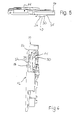
- a coin validator 10 is shown, the main plate 12 and a raceway support plate 14, the latter via hinge joints on the main plate 12 articulated and biased towards the main plate 12 by a spring, not shown is. This is general state of the art and should not be discussed further become.
- Main plate 12 and raceway support plate 14 form an open top Coin inlet opening 16. Below the coin inlet opening 16 there is a Coin channel 18.
- the track carrier plate 14 can be better seen in FIGS. 1 to 5. She points below the coin inlet opening 16 on a coin track 20 with a slope runs and roll along the coins that are thrown in through the inlet opening 16 become.
- a coin is shown at 22.
- the Münzlaubahn 20 is a test section 26 is assigned in which a plurality of sensors 26 are arranged (see also Fig. 4), which shows the different physical properties of the coins Check that roll along the coin track 20.
- the coin track 20 has a downward slope towards the coin channel.
- the coins that roll along the track 20 become the opposite Plate, here the main plate, steered towards it.
- a Damping element 30 arranged in an approximately rectangular recess 28 of the raceway support plate 14 in an approximately rectangular recess 28 of the raceway support plate 14 is a Damping element 30 arranged.
- the damping element 30 is in cross section approximately semi-cylindrical and provided with pins 32, 34 at the ends for the purpose Bearing in the raceway support plate 14.
- the axis through the pins 32, 34 is defined, runs obliquely to the coin track 20, with a slope to the upper End of the coin career 20 out (see Fig. 1).
- One is approximately parallel to the axis Ramp surface 36 formed on the damping element, which is normally in the Coin channel 18 protrudes (Fig. 6).
- the ramp area has a slope to the main slab 12 up and changes in its width dimensions along its length, i.e. it becomes narrower towards the upper end of the track 20 (see FIG. 5).
- the ramp surface 36 has a certain twist such that the in 5 right end of the ramp surface 36 with respect to the other end to the right, i.e. is twisted clockwise.
- the mass distribution of the damping element 30 with respect to its pivot axis is such that the damping element is constantly shown in the figures Position is biased, the damping element against one not closer designated stop of the support plate 14 is present.
- the damping element 30 by pivoting the passage of the coin 22 permits, the damping element is pivoted out more or less.
- the extent of the pivoting naturally also depends on the diameter and on the weight of the coin 22.
- the damping element pivots 30 only by an amount necessary to cause the coin 22 to slide down allow.
- the damping element 30 lies with its ramp surface 36 limiting edge 40 against the coin and presses it against the opposite Main plate, so that the coin in the specified position on the coin track 20 is brought and can then roll down in the same position.
- FIGS. 1 to 6 show that the coin is inserted from above. It understands that a coin can be inserted from the side, in Fig. 1 from the right. A damping element, as shown in the figures, can therefore be used in the same way. With the lateral throw-in, however, takes place no rolling down of the coin 22 on the ramp surface 36 instead.
- the damping element 30 can be made of a suitable plastic material or else consist of light metal. It builds extremely small and nevertheless leads to effective coin calming.
Landscapes
- Physics & Mathematics (AREA)
- General Physics & Mathematics (AREA)
- Testing Of Coins (AREA)
- Buildings Adapted To Withstand Abnormal External Influences (AREA)
Applications Claiming Priority (2)
| Application Number | Priority Date | Filing Date | Title |
|---|---|---|---|
| DE2000157236 DE10057236B4 (de) | 2000-11-18 | 2000-11-18 | Münzprüfer mit Dämpfungselement in der Münzlaufbahn |
| DE10057236 | 2000-11-18 |
Publications (3)
| Publication Number | Publication Date |
|---|---|
| EP1207500A2 true EP1207500A2 (fr) | 2002-05-22 |
| EP1207500A3 EP1207500A3 (fr) | 2004-06-09 |
| EP1207500B1 EP1207500B1 (fr) | 2007-01-03 |
Family
ID=7663780
Family Applications (1)
| Application Number | Title | Priority Date | Filing Date |
|---|---|---|---|
| EP20010125939 Expired - Lifetime EP1207500B1 (fr) | 2000-11-18 | 2001-10-31 | Sélecteur de pièces de monnaie |
Country Status (3)
| Country | Link |
|---|---|
| EP (1) | EP1207500B1 (fr) |
| DE (2) | DE10057236B4 (fr) |
| ES (1) | ES2278675T3 (fr) |
Families Citing this family (2)
| Publication number | Priority date | Publication date | Assignee | Title |
|---|---|---|---|---|
| DE102004020791B3 (de) * | 2004-04-28 | 2005-11-17 | National Rejectors, Inc. Gmbh | Vorrichtung zur Ablenkung und Beruhigung von Münzen in einem Münzprüfer |
| ES1062982Y (es) | 2006-05-18 | 2006-12-01 | Jofemar Sa | Selector de monedas |
Citations (4)
| Publication number | Priority date | Publication date | Assignee | Title |
|---|---|---|---|---|
| US3837454A (en) | 1971-11-04 | 1974-09-24 | Nat Rejectors Gmbh | Coin testing devices |
| EP0560830A1 (fr) | 1990-12-04 | 1993-09-22 | Mars Inc | Dispositif de guidage de pieces de monnaie. |
| EP0774146B1 (fr) | 1994-08-03 | 1998-09-30 | Coin Controls Limited | Dispositif de validation de pieces de monnaie a stabilisateur de pieces |
| DE19755467C1 (de) | 1997-12-03 | 1999-01-14 | Trenner D Wh Muenzpruefer | Münzleitvorrichtung |
Family Cites Families (3)
| Publication number | Priority date | Publication date | Assignee | Title |
|---|---|---|---|---|
| CH655810A5 (de) * | 1982-03-04 | 1986-05-15 | Autelca Ag | Muenzpruefer fuer die pruefung unterschiedlicher muenzdicken und/oder muenzdurchmesser und/oder muenzlegierungen. |
| GB9013054D0 (en) * | 1990-06-12 | 1990-08-01 | Landis & Gyr Communications | Coin escrow |
| JP2000259892A (ja) * | 1999-03-11 | 2000-09-22 | Nippon Conlux Co Ltd | 硬貨案内装置 |
-
2000
- 2000-11-18 DE DE2000157236 patent/DE10057236B4/de not_active Expired - Fee Related
-
2001
- 2001-10-31 ES ES01125939T patent/ES2278675T3/es not_active Expired - Lifetime
- 2001-10-31 DE DE50111780T patent/DE50111780D1/de not_active Expired - Lifetime
- 2001-10-31 EP EP20010125939 patent/EP1207500B1/fr not_active Expired - Lifetime
Patent Citations (4)
| Publication number | Priority date | Publication date | Assignee | Title |
|---|---|---|---|---|
| US3837454A (en) | 1971-11-04 | 1974-09-24 | Nat Rejectors Gmbh | Coin testing devices |
| EP0560830A1 (fr) | 1990-12-04 | 1993-09-22 | Mars Inc | Dispositif de guidage de pieces de monnaie. |
| EP0774146B1 (fr) | 1994-08-03 | 1998-09-30 | Coin Controls Limited | Dispositif de validation de pieces de monnaie a stabilisateur de pieces |
| DE19755467C1 (de) | 1997-12-03 | 1999-01-14 | Trenner D Wh Muenzpruefer | Münzleitvorrichtung |
Also Published As
| Publication number | Publication date |
|---|---|
| ES2278675T3 (es) | 2007-08-16 |
| DE10057236B4 (de) | 2004-03-18 |
| EP1207500A3 (fr) | 2004-06-09 |
| DE10057236A1 (de) | 2002-05-29 |
| EP1207500B1 (fr) | 2007-01-03 |
| DE50111780D1 (de) | 2007-02-15 |
Similar Documents
| Publication | Publication Date | Title |
|---|---|---|
| DE2154782B2 (de) | Anordnung zum Führen von Münzen in einer Münzpriifvorrichtung | |
| DE3208872C2 (fr) | ||
| DE3718710C2 (fr) | ||
| DE2633108A1 (de) | Muenzen-sortiervorrichtung | |
| EP1207500B1 (fr) | Sélecteur de pièces de monnaie | |
| DE3910193C1 (fr) | ||
| DE3007484C2 (fr) | ||
| EP0921501B1 (fr) | Dispositif pour le guidage de monnaies | |
| DE2455106C2 (de) | Münzautomat | |
| DE69505139T2 (de) | Münzprüfer mit münzenbewegungsdämpfungsvorrichtung | |
| DE3204114C2 (fr) | ||
| DE2912016A1 (de) | Muenzzaehl- und/oder muenzsortiervorrichtung | |
| DE60028886T2 (de) | Münzführungsvorrichtung | |
| DE2813183C3 (de) | Münzprüfer | |
| DE102007046391B4 (de) | Vorrichtung zum Sortieren von Münzen | |
| DE2221182A1 (de) | Muenzentrennvorrichtung fuer Muenzautomaten | |
| EP1209634A2 (fr) | Sélecteur de pièces de monnaie | |
| DE615877C (de) | Hinter einer Umlenkstelle angeordneter Muenzpruefer | |
| DE102009009607B4 (de) | Mechanischer Münzprüfer | |
| DE2203757C3 (de) | Münzprüfer | |
| DE102004020791B3 (de) | Vorrichtung zur Ablenkung und Beruhigung von Münzen in einem Münzprüfer | |
| DE3033617C2 (de) | Münzprüfer für selbstkassierende Vorrichtungen | |
| DE102005048836A1 (de) | Durchlaufregal zur Kommissionierung von Lagereinheiten | |
| DE3045734A1 (de) | Muenzpruefer fuer unterschiedliche muenzen | |
| DE2901007C2 (de) | Vorrichtung zum Prüfen von Münzen, welche die Bewegung einer Münze unterschiedlich stark bremst |
Legal Events
| Date | Code | Title | Description |
|---|---|---|---|
| PUAI | Public reference made under article 153(3) epc to a published international application that has entered the european phase |
Free format text: ORIGINAL CODE: 0009012 |
|
| AX | Request for extension of the european patent |
Free format text: AL;LT;LV;MK;RO;SI |
|
| PUAL | Search report despatched |
Free format text: ORIGINAL CODE: 0009013 |
|
| AK | Designated contracting states |
Kind code of ref document: A3 Designated state(s): AT BE CH CY DE DK ES FI FR GB GR IE IT LI LU MC NL PT SE TR |
|
| AX | Request for extension of the european patent |
Extension state: AL LT LV MK RO SI |
|
| RIC1 | Information provided on ipc code assigned before grant |
Ipc: 7G 07F 1/04 A |
|
| 17P | Request for examination filed |
Effective date: 20041021 |
|
| AKX | Designation fees paid |
Designated state(s): DE ES FR GB IT |
|
| 17Q | First examination report despatched |
Effective date: 20050203 |
|
| GRAP | Despatch of communication of intention to grant a patent |
Free format text: ORIGINAL CODE: EPIDOSNIGR1 |
|
| GRAS | Grant fee paid |
Free format text: ORIGINAL CODE: EPIDOSNIGR3 |
|
| GRAA | (expected) grant |
Free format text: ORIGINAL CODE: 0009210 |
|
| AK | Designated contracting states |
Kind code of ref document: B1 Designated state(s): DE ES FR GB IT |
|
| REG | Reference to a national code |
Ref country code: GB Ref legal event code: FG4D Free format text: NOT ENGLISH |
|
| GBT | Gb: translation of ep patent filed (gb section 77(6)(a)/1977) |
Effective date: 20070103 |
|
| REF | Corresponds to: |
Ref document number: 50111780 Country of ref document: DE Date of ref document: 20070215 Kind code of ref document: P |
|
| ET | Fr: translation filed | ||
| REG | Reference to a national code |
Ref country code: ES Ref legal event code: FG2A Ref document number: 2278675 Country of ref document: ES Kind code of ref document: T3 |
|
| PLBE | No opposition filed within time limit |
Free format text: ORIGINAL CODE: 0009261 |
|
| STAA | Information on the status of an ep patent application or granted ep patent |
Free format text: STATUS: NO OPPOSITION FILED WITHIN TIME LIMIT |
|
| 26N | No opposition filed |
Effective date: 20071005 |
|
| PGFP | Annual fee paid to national office [announced via postgrant information from national office to epo] |
Ref country code: FR Payment date: 20070927 Year of fee payment: 7 |
|
| REG | Reference to a national code |
Ref country code: FR Ref legal event code: ST Effective date: 20090630 |
|
| PG25 | Lapsed in a contracting state [announced via postgrant information from national office to epo] |
Ref country code: FR Free format text: LAPSE BECAUSE OF NON-PAYMENT OF DUE FEES Effective date: 20081031 |
|
| PGFP | Annual fee paid to national office [announced via postgrant information from national office to epo] |
Ref country code: GB Payment date: 20101021 Year of fee payment: 10 |
|
| PGFP | Annual fee paid to national office [announced via postgrant information from national office to epo] |
Ref country code: ES Payment date: 20101021 Year of fee payment: 10 |
|
| GBPC | Gb: european patent ceased through non-payment of renewal fee |
Effective date: 20111031 |
|
| PG25 | Lapsed in a contracting state [announced via postgrant information from national office to epo] |
Ref country code: GB Free format text: LAPSE BECAUSE OF NON-PAYMENT OF DUE FEES Effective date: 20111031 |
|
| REG | Reference to a national code |
Ref country code: ES Ref legal event code: FD2A Effective date: 20130605 |
|
| PG25 | Lapsed in a contracting state [announced via postgrant information from national office to epo] |
Ref country code: ES Free format text: LAPSE BECAUSE OF NON-PAYMENT OF DUE FEES Effective date: 20111101 |
|
| PGFP | Annual fee paid to national office [announced via postgrant information from national office to epo] |
Ref country code: DE Payment date: 20131209 Year of fee payment: 13 |
|
| PGFP | Annual fee paid to national office [announced via postgrant information from national office to epo] |
Ref country code: IT Payment date: 20131030 Year of fee payment: 13 |
|
| REG | Reference to a national code |
Ref country code: DE Ref legal event code: R119 Ref document number: 50111780 Country of ref document: DE |
|
| PG25 | Lapsed in a contracting state [announced via postgrant information from national office to epo] |
Ref country code: DE Free format text: LAPSE BECAUSE OF NON-PAYMENT OF DUE FEES Effective date: 20150501 |
|
| PG25 | Lapsed in a contracting state [announced via postgrant information from national office to epo] |
Ref country code: IT Free format text: LAPSE BECAUSE OF NON-PAYMENT OF DUE FEES Effective date: 20141031 |