EP1207593B1 - Dispositif pour fixer une barre conductrice sur un élément de support - Google Patents
Dispositif pour fixer une barre conductrice sur un élément de support Download PDFInfo
- Publication number
- EP1207593B1 EP1207593B1 EP00122903A EP00122903A EP1207593B1 EP 1207593 B1 EP1207593 B1 EP 1207593B1 EP 00122903 A EP00122903 A EP 00122903A EP 00122903 A EP00122903 A EP 00122903A EP 1207593 B1 EP1207593 B1 EP 1207593B1
- Authority
- EP
- European Patent Office
- Prior art keywords
- busbar
- current
- fixing
- recess
- wall
- Prior art date
- Legal status (The legal status is an assumption and is not a legal conclusion. Google has not performed a legal analysis and makes no representation as to the accuracy of the status listed.)
- Expired - Lifetime
Links
- 239000004020 conductor Substances 0.000 title description 16
- 229910000746 Structural steel Inorganic materials 0.000 description 10
- RYGMFSIKBFXOCR-UHFFFAOYSA-N Copper Chemical compound [Cu] RYGMFSIKBFXOCR-UHFFFAOYSA-N 0.000 description 1
- 230000015572 biosynthetic process Effects 0.000 description 1
- 229910052802 copper Inorganic materials 0.000 description 1
- 239000010949 copper Substances 0.000 description 1
- 230000005611 electricity Effects 0.000 description 1
- 238000004519 manufacturing process Methods 0.000 description 1
- 230000007935 neutral effect Effects 0.000 description 1
Images


Classifications
-
- F—MECHANICAL ENGINEERING; LIGHTING; HEATING; WEAPONS; BLASTING
- F21—LIGHTING
- F21V—FUNCTIONAL FEATURES OR DETAILS OF LIGHTING DEVICES OR SYSTEMS THEREOF; STRUCTURAL COMBINATIONS OF LIGHTING DEVICES WITH OTHER ARTICLES, NOT OTHERWISE PROVIDED FOR
- F21V21/00—Supporting, suspending, or attaching arrangements for lighting devices; Hand grips
- F21V21/34—Supporting elements displaceable along a guiding element
- F21V21/35—Supporting elements displaceable along a guiding element with direct electrical contact between the supporting element and electric conductors running along the guiding element
-
- H—ELECTRICITY
- H01—ELECTRIC ELEMENTS
- H01R—ELECTRICALLY-CONDUCTIVE CONNECTIONS; STRUCTURAL ASSOCIATIONS OF A PLURALITY OF MUTUALLY-INSULATED ELECTRICAL CONNECTING ELEMENTS; COUPLING DEVICES; CURRENT COLLECTORS
- H01R25/00—Coupling parts adapted for simultaneous co-operation with two or more identical counterparts, e.g. for distributing energy to two or more circuits
- H01R25/14—Rails or bus-bars constructed so that the counterparts can be connected thereto at any point along their length
Definitions
- the invention relates to a device for fastening a Busbar on a load-bearing element, with a device for attachment to the load-bearing element and a device for attachment to the conductor rail.
- Subject of Invention is an arrangement from a busbar and at least one in the current-carrying recess of the Busbar fastened device according to the invention as well one for engaging in the current-carrying recess of the busbar trained fastener for attaching a Lamp.
- Busbar body that either made of plastic or an electrically conductive material is and serve as a ground conductor in the latter case can.
- the busbar has a recess on one side, Depression, groove or the like on the one hand Live conductors are arranged and the other hand for Inclusion of fasteners for attaching lights is trained.
- the conductors are particularly for high-voltage busbars so arranged in the recess that they are from the outside are not easily accessible by hand.
- the of Recessing side of the busbar has a hole or the like for attachment to a wall, ceiling or the like.
- the invention has for its object a device of the type mentioned to create a simple and aesthetically pleasing mounting of a track enables.
- the invention according to claim 1 solves this problem.
- a track provided for attaching lights in the Any device that has a predetermined length section attaching one or more Luminaires enables and these lights both mechanically holds as well conductors for the power supply to these Has lights.
- This track is supposed to be attached to a load-bearing element become.
- a load-bearing element can in particular be a Ceiling, wall or the like.
- the device for fastening the busbar has on the one hand a device for attachment to this wall, ceiling or the like. It can be, for example, in known Well-designed holes for screwing to the wall or other suitable means of manufacturing a positive connection to the wall, ceiling or the like act.
- the device according to the invention has a device for attachment to the power rail and serves for fastening the busbar at a distance from the Wall, ceiling or the like. According to the invention, it is now provided that this device for engaging in the current-carrying Recess of the busbar is formed.
- the term current-carrying recess denotes that Recess, recess or groove of a busbar in the one or more current-carrying conductors arranged in this way are that when you touch the busbar with the hand of at least not directly and easily accessible from the outside are.
- a recess can, for example, be approximately U-shaped Have profile that can carry live contacts in turn within the current-carrying recess smaller recesses, undercuts or the like be housed to protect against accidental To improve touch.
- the current-carrying recess is as known in the prior art, designed for non-positive Inclusion of fasteners in the state the technology only for attaching lamps to the power rail serve. For this purpose, it can, for example, use suitable undercuts exhibit.
- the invention Fastening device for engaging in the current-carrying Recess of the track formed device, which can absorb the required holding forces and thus frictionally attached in the current-carrying recess can be.
- the invention therefore does not use the current-carrying recess only for attaching lights, but also for mounting the Track on wall, ceiling or the like.
- a busbar with separate holes or other mounting devices to be attached to the wall or ceiling, rather, for this purpose, the existing one anyway current-carrying recess, which is already used for positive locking Inclusion of lights is used. If in this Connection of an intervention in the current-carrying recess the conductor rail is an intervention meant by the opening of the recess anyway, which is a non-positive connection between the conductor rail and Fastening device manufactures.
- a particular advantage of the invention is that it is based on a simple way of fastening the busbar in this way allows the open side of the current-carrying recess points towards the wall or ceiling and thus the view withdrawn from the viewer. This allows an essential more attractive design of a lighting system, because the the current-carrying recess side of the busbar is usually not aesthetically pleasing.
- the Fastening device according to the invention can be engaged in at least one undercut of the current-carrying recess by an adjustable, in particular rotatable Latch be formed. This latch allows in its open position inserting the device for attachment on the conductor rail in the current-carrying recess, in its In the locked position, it engages behind the undercut and thus creates the non-positive connection.
- the fastening device according to the invention can consist of several assembled parts exist.
- the device for fastening For example, a fastening element can be attached to the busbar with which there are also lights on the track fasten.
- On this fastener then arranged, for example, an angle iron or the like, the other end to be attached to the wall or ceiling can.
- the connection between angle iron and fastener can be detachable.
- the invention relates to an arrangement of a Busbar and at least one in the current-carrying recess the fastening device fastened according to the invention.
- the busbar can in particular be a Be a high-voltage track.
- High-voltage track means that the supply voltage is 60 V or higher, as a rule it is between 100 and 240 V.
- the formation of the busbar as a low-voltage track is also possible.
- the arrangement is for fastening the busbar on the load-bearing element (wall, ceiling or the like) with the opening of the current-carrying recess formed. This live The recess is therefore out of view of the beholder.
- the Fastening device according to the invention preferably holds the storm rail the arrangement at a distance from the wall or Blanket so that an engagement in the opening for attachment is unhindered by lights.
- the arrangement according to the invention preferably has at least a lamp assigned to the track.
- the attachment the lamp on the power rail is preferably carried out by means of a for engaging in the current-carrying recess of the busbar trained fastener that in this way and way a non-positive connection to the power rail manufactures. It is according to the invention that this fastener to attach the lamp to one of the Opening side pioneering side of the busbar is.
- the opening side of the track is the side to which the current-carrying recess opens.
- the remaining (usually three) sides of the power rail are called designated from the opening side pages.
- the fastener can be the live connection at the same time between luminaire and conductor in the track produce, however, it is also possible to use the fastener only assign the holding function and the current-carrying Connection via a separate, current-carrying recess produce engaging device.
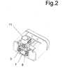
- a busbar designated overall by 1 has one current-carrying recess 2, which corresponds to that in Fig. 1 and 2 facing upward opening side of the busbar 1 opens and is accessible from this opening side.
- Within the current-carrying recess 2 are four metallic Conductors (preferably copper conductors) 3 arranged, each are recessed in a small groove around the Protection against accidental contact from the opening side to improve the current-carrying recess 2 ago. This four-pole busbar is therefore three-phase with one Neutral trained.
- the busbar 1 is bordered by a profile 4, the appealing aesthetic design.
- the attachment device for attachment the busbar 1 on a wall has an angle iron 9, for example by means of a conventional screw connection indicated at 10 can be attached to the wall.
- the second component of the fastening device is an insert which can be seen particularly well in FIG. 2 11.
- This insert 11 is by means of screws 17 on Angle iron 9 screwed tight.
- the angle iron 9 and the insert 11 then together form a fastening device according to claim 1.
- the insert 11 can into the recess 2 by means of the latch 8 already mentioned the busbar 1 are used.
- the bolt 8 By twisting the Handle 18, the bolt 8 is brought into the locked position, the rotational movement being transmitted by means of the spring 19 becomes. In this way, the busbar 1 with the Angle iron 9 connected.
- the angle iron 9 is for Attaching the conductor rail to a wall with the wall facing upwards Opening side trained.
- This angle iron can be used in same way for attaching the track to a ceiling and be formed at a distance from the ceiling, such as For example, indicated in Fig. 4.
- FIG. 3 and 4 is the attachment of a shuttle light on an inventive with the opening side facing up Busbar arrangement shown schematically.
- This Attachment takes place by means of a fastening element according to the invention, one insert 11 (this is the same as the insert 11 of FIG. 2) and a so connected angle element or an angle iron 12.
- the shuttle train light 14 away from the opening side of the busbar 1.
- the attachment point 15 of the shuttle light 14 at the angle 12 and thus the fastener according to the invention consisting of Insert 11 and angle 12 is also on one of the opening side of the conductor rail 1 side. How 4, the lamp 14 is powered with electricity by means of a separate into the current-carrying recess 2 of the busbar 1 used element 16.
Landscapes
- Engineering & Computer Science (AREA)
- General Engineering & Computer Science (AREA)
- Installation Of Bus-Bars (AREA)
- Housings And Mounting Of Transformers (AREA)
- Cable Accessories (AREA)
- Rolling Contact Bearings (AREA)
Claims (6)
- Dispositif constitué d'un rail électrique prévu pour y placer des lampes (14), d'un dispositif de fixation du rail électrique (1) au mur ou au plafond ainsi que d'un élément de fixation (11, 12) pour placer une lampe (14) sur le rail électrique (1), le rail électrique (1) présentant un évidement (2) conduisant le courant et le dispositif de fixation étant pourvu d'un équipement (10) pour la fixation au mur ou au plafond, et l'évidement (2) conduisant le courant se trouvant sur le côté du rail électrique dirigé vers le mur ou le plafond, caractérisé en ce que le dispositif de fixation est pourvu d'un équipement (11) pour la fixation au rail électrique au moyen d'une liaison à force, par engagement dans l'évidement (2) conduisant le courant du rail électrique (1), et en ce que l'élément de fixation (11, 12) est réalisé en tant que cornière afin de disposer la lampe (14) sur un côté du rail électrique (1) opposé à l'évidement conduisant le courant.
- Dispositif selon la revendication 1, caractérisé en ce que l'équipement (11) pour la fixation au rail électrique est conçu pour l'engagement dans au moins un détalonnage de l'évidement (2), conduisant le courant, du rail électrique (1).
- Dispositif selon la revendication 2, caractérisé en ce que l'engagement dans au moins un détalonnage s'effectue au moyen d'un verrou (8) déplaçable, en particulier tournant.
- Dispositif selon l'une des revendications 1 à 3, caractérisé en ce que le rail électrique (1) est un rail électrique à haute tension.
- Dispositif selon l'une des revendications 1 à 4, caractérisé en ce qu'il est conçu pour la fixation du rail électrique (1) au mur ou au plafond avec l'ouverture de l'évidement conduisant le courant, dirigée vers cet élément porteur.
- Dispositif selon la revendication 4 ou 5, caractérisé en ce qu'il comporte au moins une lampe (14) associée au rail électrique (1).
Priority Applications (3)
| Application Number | Priority Date | Filing Date | Title |
|---|---|---|---|
| EP00122903A EP1207593B1 (fr) | 2000-10-20 | 2000-10-20 | Dispositif pour fixer une barre conductrice sur un élément de support |
| AT00122903T ATE277437T1 (de) | 2000-10-20 | 2000-10-20 | Vorrichtung zur befestigung einer stromschiene an einem tragenden element |
| DE50007926T DE50007926D1 (de) | 2000-10-20 | 2000-10-20 | Vorrichtung zur Befestigung einer Stromschiene an einem tragenden Element |
Applications Claiming Priority (1)
| Application Number | Priority Date | Filing Date | Title |
|---|---|---|---|
| EP00122903A EP1207593B1 (fr) | 2000-10-20 | 2000-10-20 | Dispositif pour fixer une barre conductrice sur un élément de support |
Publications (2)
| Publication Number | Publication Date |
|---|---|
| EP1207593A1 EP1207593A1 (fr) | 2002-05-22 |
| EP1207593B1 true EP1207593B1 (fr) | 2004-09-22 |
Family
ID=8170152
Family Applications (1)
| Application Number | Title | Priority Date | Filing Date |
|---|---|---|---|
| EP00122903A Expired - Lifetime EP1207593B1 (fr) | 2000-10-20 | 2000-10-20 | Dispositif pour fixer une barre conductrice sur un élément de support |
Country Status (3)
| Country | Link |
|---|---|
| EP (1) | EP1207593B1 (fr) |
| AT (1) | ATE277437T1 (fr) |
| DE (1) | DE50007926D1 (fr) |
Family Cites Families (3)
| Publication number | Priority date | Publication date | Assignee | Title |
|---|---|---|---|---|
| DE2915502C2 (de) * | 1979-04-17 | 1984-01-26 | Erco Leuchten GmbH, 5880 Lüdenscheid | Stromentnahmeschiene |
| EP0527674A1 (fr) * | 1991-08-09 | 1993-02-17 | Roberto Foottit | Système de distribution d'électricité et/ou d'éclairage à point de connexion continu |
| DE9414033U1 (de) * | 1994-08-30 | 1994-11-03 | Taiwan King Prince Co., Ltd., Taipeh/T'ai-pei | Befestigungsanordnung für Lichtschienen |
-
2000
- 2000-10-20 AT AT00122903T patent/ATE277437T1/de not_active IP Right Cessation
- 2000-10-20 DE DE50007926T patent/DE50007926D1/de not_active Expired - Lifetime
- 2000-10-20 EP EP00122903A patent/EP1207593B1/fr not_active Expired - Lifetime
Also Published As
| Publication number | Publication date |
|---|---|
| DE50007926D1 (de) | 2004-10-28 |
| ATE277437T1 (de) | 2004-10-15 |
| EP1207593A1 (fr) | 2002-05-22 |
Similar Documents
| Publication | Publication Date | Title |
|---|---|---|
| DE10025648B4 (de) | Stromschienensystem | |
| DE10025646A1 (de) | Stromschienensystem | |
| EP1284035B1 (fr) | Systeme de rails conducteurs | |
| WO2021069302A1 (fr) | Barre omnibus pour lampes ou unités électriques | |
| EP1994614B1 (fr) | Construction a cadre pour une armoire electrique, armoire electrique et kit pour l'armoire electrique | |
| DE4124066C2 (de) | Elektrisches Leuchtensystem | |
| EP0739618B1 (fr) | Unité d'alimentation pour chambres de malade | |
| EP0466043B1 (fr) | Installation de distribution comprenant au moins deux rangées d'appareils électriques de type étroit | |
| EP1473807A1 (fr) | dispositif de barres omnibus pour éclairage et élement de verrouillage | |
| EP1207593B1 (fr) | Dispositif pour fixer une barre conductrice sur un élément de support | |
| EP1193822B1 (fr) | Support de barres bus | |
| DE10241941B4 (de) | Leuchtensystem, Adaptionsglied und Leuchte damit | |
| EP0921595B1 (fr) | Boíte de jonction | |
| DE19710055C2 (de) | Kabelübergangs- und Sicherungskasten | |
| DE1905735A1 (de) | Abhaengbare Deckenkonstruktion | |
| EP1665474A1 (fr) | Systeme barre omnibus | |
| EP0304513B1 (fr) | Dispositif d'éclairage à basse tension | |
| DE3007970A1 (de) | Elektrische schaltanlage | |
| EP0725458A2 (fr) | Rail profilé d'un meuble ou d'un autre élément | |
| DE202006020037U1 (de) | Rahmenkonstruktion für einen Schaltschrank, Schaltschrank und Bausatz für den Schaltschrank | |
| DE9101721U1 (de) | Leuchte mit einer langgestreckten Tragschiene für mehrere in deren Längsrichtung hintereinanderliegend angeordnete Lampen | |
| EP0340532A2 (fr) | Lampe à basse tension | |
| DE19758465C2 (de) | Elektrische Schiebeklemme | |
| EP4189288A1 (fr) | Composant de réglette lumineuse et système de réglette lumineuse | |
| DE20101581U1 (de) | Hochvolt-Stromschienensystem |
Legal Events
| Date | Code | Title | Description |
|---|---|---|---|
| PUAI | Public reference made under article 153(3) epc to a published international application that has entered the european phase |
Free format text: ORIGINAL CODE: 0009012 |
|
| AX | Request for extension of the european patent |
Free format text: AL;LT;LV;MK;RO;SI |
|
| 17P | Request for examination filed |
Effective date: 20020514 |
|
| RAP1 | Party data changed (applicant data changed or rights of an application transferred) |
Owner name: TOBIAS GRAU |
|
| 17Q | First examination report despatched |
Effective date: 20020903 |
|
| AKX | Designation fees paid |
Designated state(s): AT BE CH CY DE DK ES FI FR GB GR IE IT LI LU MC NL PT SE |
|
| GRAP | Despatch of communication of intention to grant a patent |
Free format text: ORIGINAL CODE: EPIDOSNIGR1 |
|
| GRAS | Grant fee paid |
Free format text: ORIGINAL CODE: EPIDOSNIGR3 |
|
| GRAA | (expected) grant |
Free format text: ORIGINAL CODE: 0009210 |
|
| RIN1 | Information on inventor provided before grant (corrected) |
Inventor name: TOBIAS GRAU |
|
| AK | Designated contracting states |
Kind code of ref document: B1 Designated state(s): AT BE CH CY DE DK ES FI FR GB GR IE IT LI LU MC NL PT SE |
|
| PG25 | Lapsed in a contracting state [announced via postgrant information from national office to epo] |
Ref country code: CY Free format text: LAPSE BECAUSE OF FAILURE TO SUBMIT A TRANSLATION OF THE DESCRIPTION OR TO PAY THE FEE WITHIN THE PRESCRIBED TIME-LIMIT Effective date: 20040922 Ref country code: FI Free format text: LAPSE BECAUSE OF FAILURE TO SUBMIT A TRANSLATION OF THE DESCRIPTION OR TO PAY THE FEE WITHIN THE PRESCRIBED TIME-LIMIT Effective date: 20040922 Ref country code: IE Free format text: LAPSE BECAUSE OF FAILURE TO SUBMIT A TRANSLATION OF THE DESCRIPTION OR TO PAY THE FEE WITHIN THE PRESCRIBED TIME-LIMIT Effective date: 20040922 Ref country code: GB Free format text: LAPSE BECAUSE OF FAILURE TO SUBMIT A TRANSLATION OF THE DESCRIPTION OR TO PAY THE FEE WITHIN THE PRESCRIBED TIME-LIMIT Effective date: 20040922 Ref country code: FR Free format text: LAPSE BECAUSE OF FAILURE TO SUBMIT A TRANSLATION OF THE DESCRIPTION OR TO PAY THE FEE WITHIN THE PRESCRIBED TIME-LIMIT Effective date: 20040922 |
|
| REG | Reference to a national code |
Ref country code: GB Ref legal event code: FG4D Free format text: NOT ENGLISH |
|
| REG | Reference to a national code |
Ref country code: CH Ref legal event code: EP |
|
| PG25 | Lapsed in a contracting state [announced via postgrant information from national office to epo] |
Ref country code: LU Free format text: LAPSE BECAUSE OF NON-PAYMENT OF DUE FEES Effective date: 20041020 |
|
| REG | Reference to a national code |
Ref country code: IE Ref legal event code: FG4D Free format text: GERMAN |
|
| REF | Corresponds to: |
Ref document number: 50007926 Country of ref document: DE Date of ref document: 20041028 Kind code of ref document: P |
|
| PG25 | Lapsed in a contracting state [announced via postgrant information from national office to epo] |
Ref country code: BE Free format text: LAPSE BECAUSE OF NON-PAYMENT OF DUE FEES Effective date: 20041031 Ref country code: MC Free format text: LAPSE BECAUSE OF NON-PAYMENT OF DUE FEES Effective date: 20041031 |
|
| REG | Reference to a national code |
Ref country code: CH Ref legal event code: NV Representative=s name: TROESCH SCHEIDEGGER WERNER AG |
|
| PG25 | Lapsed in a contracting state [announced via postgrant information from national office to epo] |
Ref country code: SE Free format text: LAPSE BECAUSE OF FAILURE TO SUBMIT A TRANSLATION OF THE DESCRIPTION OR TO PAY THE FEE WITHIN THE PRESCRIBED TIME-LIMIT Effective date: 20041222 Ref country code: DK Free format text: LAPSE BECAUSE OF FAILURE TO SUBMIT A TRANSLATION OF THE DESCRIPTION OR TO PAY THE FEE WITHIN THE PRESCRIBED TIME-LIMIT Effective date: 20041222 Ref country code: GR Free format text: LAPSE BECAUSE OF FAILURE TO SUBMIT A TRANSLATION OF THE DESCRIPTION OR TO PAY THE FEE WITHIN THE PRESCRIBED TIME-LIMIT Effective date: 20041222 |
|
| PG25 | Lapsed in a contracting state [announced via postgrant information from national office to epo] |
Ref country code: ES Free format text: LAPSE BECAUSE OF FAILURE TO SUBMIT A TRANSLATION OF THE DESCRIPTION OR TO PAY THE FEE WITHIN THE PRESCRIBED TIME-LIMIT Effective date: 20050102 |
|
| GBV | Gb: ep patent (uk) treated as always having been void in accordance with gb section 77(7)/1977 [no translation filed] |
Effective date: 20040922 |
|
| REG | Reference to a national code |
Ref country code: IE Ref legal event code: FD4D |
|
| BERE | Be: lapsed |
Owner name: TOBIAS GRAU Effective date: 20041031 |
|
| PLBE | No opposition filed within time limit |
Free format text: ORIGINAL CODE: 0009261 |
|
| STAA | Information on the status of an ep patent application or granted ep patent |
Free format text: STATUS: NO OPPOSITION FILED WITHIN TIME LIMIT |
|
| 26N | No opposition filed |
Effective date: 20050623 |
|
| EN | Fr: translation not filed | ||
| BERE | Be: lapsed |
Owner name: *TOBIAS GRAU Effective date: 20041031 |
|
| PG25 | Lapsed in a contracting state [announced via postgrant information from national office to epo] |
Ref country code: PT Free format text: LAPSE BECAUSE OF NON-PAYMENT OF DUE FEES Effective date: 20050222 |
|
| PGFP | Annual fee paid to national office [announced via postgrant information from national office to epo] |
Ref country code: AT Payment date: 20091022 Year of fee payment: 10 Ref country code: CH Payment date: 20091026 Year of fee payment: 10 |
|
| PGFP | Annual fee paid to national office [announced via postgrant information from national office to epo] |
Ref country code: NL Payment date: 20091027 Year of fee payment: 10 |
|
| PGFP | Annual fee paid to national office [announced via postgrant information from national office to epo] |
Ref country code: IT Payment date: 20091024 Year of fee payment: 10 |
|
| REG | Reference to a national code |
Ref country code: NL Ref legal event code: V1 Effective date: 20110501 |
|
| REG | Reference to a national code |
Ref country code: CH Ref legal event code: PL |
|
| PG25 | Lapsed in a contracting state [announced via postgrant information from national office to epo] |
Ref country code: LI Free format text: LAPSE BECAUSE OF NON-PAYMENT OF DUE FEES Effective date: 20101031 Ref country code: CH Free format text: LAPSE BECAUSE OF NON-PAYMENT OF DUE FEES Effective date: 20101031 |
|
| PG25 | Lapsed in a contracting state [announced via postgrant information from national office to epo] |
Ref country code: AT Free format text: LAPSE BECAUSE OF NON-PAYMENT OF DUE FEES Effective date: 20101020 Ref country code: NL Free format text: LAPSE BECAUSE OF NON-PAYMENT OF DUE FEES Effective date: 20110501 |
|
| PG25 | Lapsed in a contracting state [announced via postgrant information from national office to epo] |
Ref country code: IT Free format text: LAPSE BECAUSE OF NON-PAYMENT OF DUE FEES Effective date: 20101020 |
|
| PGFP | Annual fee paid to national office [announced via postgrant information from national office to epo] |
Ref country code: DE Payment date: 20130307 Year of fee payment: 14 |
|
| REG | Reference to a national code |
Ref country code: DE Ref legal event code: R119 Ref document number: 50007926 Country of ref document: DE |
|
| PG25 | Lapsed in a contracting state [announced via postgrant information from national office to epo] |
Ref country code: DE Free format text: LAPSE BECAUSE OF NON-PAYMENT OF DUE FEES Effective date: 20150501 |