EP1207603A2 - Installation de commutation à isolation gazeuse - Google Patents
Installation de commutation à isolation gazeuse Download PDFInfo
- Publication number
- EP1207603A2 EP1207603A2 EP01126497A EP01126497A EP1207603A2 EP 1207603 A2 EP1207603 A2 EP 1207603A2 EP 01126497 A EP01126497 A EP 01126497A EP 01126497 A EP01126497 A EP 01126497A EP 1207603 A2 EP1207603 A2 EP 1207603A2
- Authority
- EP
- European Patent Office
- Prior art keywords
- gas
- switching apparatus
- insulated switching
- pressurized air
- insulation
- Prior art date
- Legal status (The legal status is an assumption and is not a legal conclusion. Google has not performed a legal analysis and makes no representation as to the accuracy of the status listed.)
- Withdrawn
Links
Images


Classifications
-
- H—ELECTRICITY
- H01—ELECTRIC ELEMENTS
- H01H—ELECTRIC SWITCHES; RELAYS; SELECTORS; EMERGENCY PROTECTIVE DEVICES
- H01H33/00—High-tension or heavy-current switches with arc-extinguishing or arc-preventing means
-
- H—ELECTRICITY
- H02—GENERATION; CONVERSION OR DISTRIBUTION OF ELECTRIC POWER
- H02B—BOARDS, SUBSTATIONS OR SWITCHING ARRANGEMENTS FOR THE SUPPLY OR DISTRIBUTION OF ELECTRIC POWER
- H02B13/00—Arrangement of switchgear in which switches are enclosed in, or structurally associated with, a casing, e.g. cubicle
- H02B13/02—Arrangement of switchgear in which switches are enclosed in, or structurally associated with, a casing, e.g. cubicle with metal casing
- H02B13/035—Gas-insulated switchgear
- H02B13/055—Features relating to the gas
-
- H—ELECTRICITY
- H01—ELECTRIC ELEMENTS
- H01H—ELECTRIC SWITCHES; RELAYS; SELECTORS; EMERGENCY PROTECTIVE DEVICES
- H01H33/00—High-tension or heavy-current switches with arc-extinguishing or arc-preventing means
- H01H33/02—Details
- H01H33/53—Cases; Reservoirs, tanks, piping or valves, for arc-extinguishing fluid; Accessories therefor, e.g. safety arrangements, pressure relief devices
- H01H33/56—Gas reservoirs
- H01H2033/566—Avoiding the use of SF6
Definitions
- the present invention relates to a gas-insulated switching apparatus used for power systems and distribution systems and, more particularly, to a sealed gas-insulated switching apparatus.
- Japanese Patent Laid-Open No. 141105/1985 discloses a technique of using dry air as the insulation gas instead of sulfur hexafluoride because of the following problem. That portion of the gas-insulated switching apparatus which requires inspection most frequently is the circuit breaker. Where sulfur hexafluoride is used as the insulation gas, work of removing sulfur hexafluoride from the apparatus and recharging the apparatus with it is necessary in every inspection. A sulfur hexafluoride cylinder is needed to compensate for loss of sulfur hexafluoride due to its removal and recharging with it as well as to perform recharging. In this technique, dry air is compressed by a pressure pump and stored in a cylinder. When necessary, dry air is supplied from the cylinder to the gas-insulated switching apparatus. In the gas-insulated switching apparatus, the dry air is used in a non-pressurized state.
- gas-insulated switching apparatuses now tend to be decreased in size to meet market needs. Although the decrease in size requires that the air used in gas-insulated switching apparatuses have a higher withstand voltage than in previous cases, non-pressurized dry air, which is used conventionally, cannot satisfy the requirement.
- the insulation gas that is sealed in the sealing container is required to have a particularly high withstand voltage, though they can be made smaller than other types of gas-insulated switching apparatuses because the former can provide much shorter interphase insulation distance and insulation distance to the earth than the latter.
- the invention has been made in view of the above circumstances in the related art, and an object of the invention is therefore to satisfy the recent requirements for gas-insulated switching apparatuses and hence to provide a gas-insulated switching apparatus in which insulation is attained by air having a high withst and voltage. Another object of the invention is to provide a gas-insulated switching apparatus that can be made even smaller than conventional ones.
- a gas-insulated switching apparatus comprises a sealing container including a switch accommodated therein, wherein dry pressurized air as an insulation gas is sealed in the container.
- Dry pressurized air In contrast to sulfur hexafluoride that has frequently been used conventionally, dry pressurized air is completely harmless and hence never deteriorates the earth environments. Dry pressurized air can be acquired easily and inexpensively by, for example, compressing and storing it in a cylinder by the pump, for example, a method that is disclosed in Japanese Patent Laid-Open No. 141105/1985 and supplying it to the gas-insulated switching apparatus when necessary.
- the dry pressurized air has a pressure of 0.11 to 0.3 MPa.
- the dry pressurized air has a water content that is no more than 3,000 ppm in terms of a volume ratio of a volume of water vapor in which a vapor partial pressure of the dry pressurized air is converted to be 101,325 Pa.
- the dry pressurized air is given a much superior breakdown voltage characteristic if the dry pressurized air has a pressure of 0.11 to 0.3 Mpa and the dry pressurized air has a water content that is no more than 3,000 ppm. If the pressure of the dry pressurized air is set greater than or equal to 0.11 MPa, the problem that external moist air enters the sealed container in which the switch is accommodated can be solved, whereby the gas insulation performance of the sealed container can be kept for a long time.
- insulation barriers are provided between charged portions and grounded portions of the switch and between the charged portions.
- the sealed container and hence the gas-insulated switching apparatus can be made even smaller than in conventional cases by employing a composite insulation method in which the insulation function of the insulation barriers is added to the above-described gas insulation performance of the dry pressurized air.
- the switch is a vacuum valve.
- the breaking performance of the switch is improved and no decomposed components occur due to an arc that would otherwise occur at the time of opening or closing. This results in an advantage that the gas insulation performance of the dry pressurized air is kept stably.
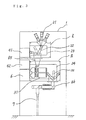
- Figs. 1 and 2 are for description of a gas-insulated switching apparatus according to a first embodiment of the invention.
- Fig. 1 is an explanatory diagram showing the configuration of the first embodiment.
- Fig. 2 is a graph showing a relationship between the gas pressure and the breakdown voltage of dry pressurized air.
- reference numeral 1 denotes a gas-insulated switching apparatus; 2, a first sealed container; 21, insulated bus lines; 22, bus line disconnectors; 3, a second sealed container; 31, circuit breakers; 32, disconnectors for receiving electric power; 33, grounding switches; 4, a disconnector operating mechanism; 5, an operating mechanism for grounding switches; 6, a circuit breaker operating mechanism; and 7, cables for receiving electric power.
- Three bus line disconnectors 22, circuit breakers 31, disconnectors 32, and grounding switches 33 are provided for the respective phases of the three-phase insulated bus lines 21.
- the bus lines 21 and the bus line disconnectors 22 are accommodated in the first sealed container 2, and the circuit breakers 31, the disconnectors 32, and the grounding switches 33 are accommodated in the second sealed container 3.
- Dry pressurized air is sealed to occupy the space of each of the first sealed container 2 and the second sealed container 3.
- the pressure (this is the total pressure including a water vapor partial pressure; this also applies to the following description) of the dry pressurized air is 0.2 MPa and its water content (the volume ratio of the volume of the water vapor in which the water vapor partial pressure of the dry pressurized air is converted to be 101,325 Pa; this also applies to the following description) is 1,500 ppm.
- the disconnector operating mechanism 4, the switch operating mechanism 5, the breaker operating mechanism 6, and the cables 7 are provided outside the sealing containers 2 and 3.
- the bus lines 22 are connected to fixed electrodes of the circuit breakers 31 via insulation bushings 81. Movable electrodes of the circuit breakers 31 are connected to the disconnectors 32 via insulation bushings 82. The disconnectors 32 are connected to the cables 7 via insulation bushings 83 and transformers CT. The insulation bushings 83 are provided in the second sealed container 3.
- Fig. 2 is a graph showing a relationship between the air pressure and the breakdown voltage of dry area (water content: 3,000 ppm or less) that was presented in CH1583-4/80/0000-0034$00.75, 1980 IEEE.
- the horizontal axis represents the gas pressure (in kPa), and the vertical axis represents the breakdown voltage with a normalization in which a breakdown voltage at the atmospheric pressure is given a value "1.”
- the breakdown voltages shown in Fig. 2 are ones that were measured by a bar-flat plate positive lightning impulse testing method which is considered the severest measuring method of such dielectric strength.
- the breakdown voltage increases with increase of the dry air pressure and is saturated around a dry air pressure 0.30 MPa.
- an unduly low dry air pressure should cause a problem that external moist air enters the first sealed container 2 and the second sealed container 3. Since it is necessary to prevent such entrance of external air and to provide a good breakdown voltage characteristic, the invention employs dry pressurized air in a pressure range of 0.11 to 0.30 MPa.
- the water content of the dry pressurized air is no more than 3,000 ppm, particularly no more than 2,000 ppm. Therefore, the dry pressurized air that is used in the first embodiment is a preferred example of the dry pressurized air according to the invention.
- Fig. 3 is an explanatory diagram showing the configuration of a gas-insulated switching apparatus according to a second embodiment of the invention.
- reference numeral 1 denotes a gas-insulated switching apparatus; 2, a first sealed container; 21, insulated bus lines; 22, bus line disconnectors; 23, insulation barriers; 3, a second sealed container; 31, circuit breakers (vacuum valve breakers); 32, disconnectors for receiving electric power; 34, insulation barriers; 41, an operating mechanism for bus line disconnectors; 42, an operating mechanism for disconnectors for receiving electric power; 6, a circuit breaker operating mechanism; and 7, cables for receiving electric power.
- Three bus line disconnectors 22, insulation barriers 23, circuit breakers 31, disconnectors 32 for receiving electric power, and insulation barriers 34 are provided for the respective phases of the three-phase insulated bus lines 21.
- the bus lines 21, the bus line disconnectors 22, and the insulation barriers 23 are accommodated in the first sealed container 2, and the circuit breakers 31, the disconnectors 32 for receiving electric power, and the insulation barriers 34 are accommodated in the second sealed container 3.
- Dry pressurized air is sealed to occupy the space of each of the first sealed container 2 and the second sealed container 3.
- the pressure of the dry pressurized air is 0.25 MPa and its water content is 1,000 ppm.
- the operating mechanism 41 for bus line disconnectors, the operating mechanism 42 for disconnectors for receiving electric power, the breaker operating mechanism 6, the cables 7, etc. are provided outside the sealing containers 2 and 3.
- the bus line disconnectors 22 are connected to fixed electrodes of the circuit breakers 31 via insulation bushings 85. Movable electrodes of the circuit breakers 31 are connected to the disconnectors 32 for receiving electric power. The disconnectors 32 for receiving electric power are connected to the cables 7 via insulation bushings 86.
- Vacuum switching valve (not shown ) are used for the circuit breaker 31. In such vacuum switching valve, moving electrode are moved to fixed electrode to switch circuit lines connection state and disconnection states.
- the insulation barriers 23 serve as insulation barriers between conductor charged portions of the three respective phases in the first sealed container 2.
- the insulation barriers 34 serve as insulation barriers between a plurality of charged portions in the second sealed container 3 and between these charged portions and grounded portions.
- the insulation barriers 23 and 34 are made of an electric insulation material such as an epoxy resin plate, a glass epoxy lamination plate, or a glass base unsaturated polyester resin type molding material.
- the switch may be the bus line disconnector, the circuit breaker, the vacuum switching valve, the disconnector for receiving electric power, or the grounding switch shown in Fig. 1 and 3 or some other switch such as a load switch.
Landscapes
- Engineering & Computer Science (AREA)
- Power Engineering (AREA)
- Gas-Insulated Switchgears (AREA)
- High-Tension Arc-Extinguishing Switches Without Spraying Means (AREA)
Applications Claiming Priority (2)
| Application Number | Priority Date | Filing Date | Title |
|---|---|---|---|
| JP2000352092A JP2002159109A (ja) | 2000-11-20 | 2000-11-20 | ガス絶縁開閉装置 |
| JP2000352092 | 2000-11-20 |
Publications (2)
| Publication Number | Publication Date |
|---|---|
| EP1207603A2 true EP1207603A2 (fr) | 2002-05-22 |
| EP1207603A3 EP1207603A3 (fr) | 2004-09-22 |
Family
ID=18825041
Family Applications (1)
| Application Number | Title | Priority Date | Filing Date |
|---|---|---|---|
| EP01126497A Withdrawn EP1207603A3 (fr) | 2000-11-20 | 2001-11-12 | Installation de commutation à isolation gazeuse |
Country Status (8)
| Country | Link |
|---|---|
| US (1) | US20020060204A1 (fr) |
| EP (1) | EP1207603A3 (fr) |
| JP (1) | JP2002159109A (fr) |
| KR (1) | KR20020039244A (fr) |
| CN (1) | CN1176514C (fr) |
| HK (1) | HK1044635B (fr) |
| SG (1) | SG115426A1 (fr) |
| TW (1) | TW569514B (fr) |
Cited By (1)
| Publication number | Priority date | Publication date | Assignee | Title |
|---|---|---|---|---|
| CN111091998A (zh) * | 2018-10-23 | 2020-05-01 | 福建工程学院 | 户外小型化高压交流隔离串联联动真空断路器 |
Families Citing this family (21)
| Publication number | Priority date | Publication date | Assignee | Title |
|---|---|---|---|---|
| TWI228339B (en) * | 2002-11-06 | 2005-02-21 | Mitsubishi Electric Corp | Metal-enclosed switchgear |
| JP4400089B2 (ja) * | 2003-05-08 | 2010-01-20 | 富士電機システムズ株式会社 | 密閉形ガス絶縁開閉装置 |
| JP4237591B2 (ja) * | 2003-09-17 | 2009-03-11 | 株式会社日立製作所 | ガス絶縁開閉装置 |
| JP4360234B2 (ja) * | 2004-03-12 | 2009-11-11 | 三菱電機株式会社 | ガス絶縁開閉装置 |
| JP5054661B2 (ja) * | 2008-03-12 | 2012-10-24 | 日立建機株式会社 | 電気駆動式作業機械 |
| CN101854036B (zh) * | 2009-03-31 | 2012-06-06 | 青岛特锐德电气股份有限公司 | 空气开关柜 |
| US8592708B2 (en) * | 2009-05-18 | 2013-11-26 | Hitachi, Ltd. | Gas-insulated vacuum circuit breaker |
| CN102484360B (zh) * | 2009-10-29 | 2014-08-27 | 三菱电机株式会社 | 电气开关装置 |
| SE534914C2 (sv) * | 2010-06-18 | 2012-02-14 | Otto Electric Ltd | Ställverk med enfasisolering bestående av luftisolering och skärmar |
| KR101467607B1 (ko) * | 2010-12-16 | 2014-12-02 | 현대중공업 주식회사 | 가스 절연 개폐장치 |
| CN102315605B (zh) * | 2011-05-13 | 2014-09-10 | 常州森隆电力科技有限公司 | 正压力全密封固体绝缘开关特种设备 |
| KR101269020B1 (ko) * | 2011-10-10 | 2013-06-04 | 한국전력공사 | 건조공기를 사용한 가스절연개폐장치의 검수시험 방법 및 장치 |
| JP6094028B2 (ja) * | 2011-12-22 | 2017-03-15 | 株式会社明電舎 | 真空遮断器 |
| CN104937793B (zh) * | 2013-01-15 | 2017-04-12 | 三菱电机株式会社 | 气体绝缘开关装置 |
| EP2958205B1 (fr) * | 2013-02-13 | 2019-03-27 | Mitsubishi Electric Corporation | Appareillage de connexion à isolation gazeuse |
| WO2016157495A1 (fr) * | 2015-04-02 | 2016-10-06 | 三菱電機株式会社 | Appareillage de commutation à isolation gazeuse |
| WO2022085544A1 (fr) * | 2020-10-22 | 2022-04-28 | Agc株式会社 | Équipement électrique |
| CN115236503B (zh) * | 2022-07-27 | 2024-08-09 | 西安交通大学 | 一种用于开关工频耐压动态绝缘测试的回路及方法 |
| GB202304942D0 (en) * | 2023-04-03 | 2023-05-17 | Eaton Intelligent Power Ltd | Compact switching appartus |
| PL4443462T3 (pl) * | 2023-04-03 | 2026-04-07 | Eaton Intelligent Power Limited | Kompaktowe urządzenie przełączające |
| KR102767860B1 (ko) * | 2023-04-25 | 2025-02-12 | 권갑순 | Dry air 가스절연 개폐장치의 오염도 및 압력 상태 감시시스템 |
Family Cites Families (6)
| Publication number | Priority date | Publication date | Assignee | Title |
|---|---|---|---|---|
| US3155471A (en) * | 1959-05-01 | 1964-11-03 | Ite Circuit Breaker Ltd | Dry air system for isolated phase bus |
| GB1125750A (en) * | 1966-08-24 | 1968-08-28 | Ass Elect Ind | Improvements in and relating to electric circuit breakers |
| FR2082144A5 (fr) * | 1970-03-04 | 1971-12-10 | Merlin Gerin | |
| SU517071A1 (ru) * | 1974-07-30 | 1976-06-05 | Предприятие П/Я В-8360 | Высоковольтный коммутационный аппарат |
| DE2702767C2 (de) * | 1977-01-24 | 1982-09-09 | Brown, Boveri & Cie Ag, 6800 Mannheim | Verfahren zum Trocknen von Druckluft für elektrische Schaltzwecke und Trockenvorrichtung zur Durchführung des Verfahrens |
| JP3667150B2 (ja) * | 1999-05-21 | 2005-07-06 | 三菱電機株式会社 | ガス封入開閉装置 |
-
2000
- 2000-11-20 JP JP2000352092A patent/JP2002159109A/ja active Pending
-
2001
- 2001-10-26 TW TW090126549A patent/TW569514B/zh not_active IP Right Cessation
- 2001-11-05 SG SG200106750A patent/SG115426A1/en unknown
- 2001-11-12 EP EP01126497A patent/EP1207603A3/fr not_active Withdrawn
- 2001-11-15 CN CNB011374764A patent/CN1176514C/zh not_active Expired - Fee Related
- 2001-11-19 KR KR1020010071682A patent/KR20020039244A/ko not_active Ceased
- 2001-11-19 US US09/988,287 patent/US20020060204A1/en not_active Abandoned
-
2002
- 2002-08-23 HK HK02106217.2A patent/HK1044635B/zh not_active IP Right Cessation
Cited By (1)
| Publication number | Priority date | Publication date | Assignee | Title |
|---|---|---|---|---|
| CN111091998A (zh) * | 2018-10-23 | 2020-05-01 | 福建工程学院 | 户外小型化高压交流隔离串联联动真空断路器 |
Also Published As
| Publication number | Publication date |
|---|---|
| HK1044635B (zh) | 2005-05-20 |
| CN1354538A (zh) | 2002-06-19 |
| SG115426A1 (en) | 2005-10-28 |
| TW569514B (en) | 2004-01-01 |
| CN1176514C (zh) | 2004-11-17 |
| KR20020039244A (ko) | 2002-05-25 |
| HK1044635A1 (en) | 2002-10-25 |
| US20020060204A1 (en) | 2002-05-23 |
| JP2002159109A (ja) | 2002-05-31 |
| EP1207603A3 (fr) | 2004-09-22 |
Similar Documents
| Publication | Publication Date | Title |
|---|---|---|
| EP1207603A2 (fr) | Installation de commutation à isolation gazeuse | |
| KR101445479B1 (ko) | 스위치 기어 | |
| US8710388B2 (en) | Switchgear and method for operating switchgear | |
| CN1825725B (zh) | 真空开关装置 | |
| JP2003047113A (ja) | 開閉装置 | |
| US6444937B1 (en) | Gas-insulated switching device | |
| US6292356B1 (en) | Gas insulation switch | |
| US8462485B2 (en) | Switchgear for underground electric power distribution line | |
| JPH11164429A (ja) | 接地装置付き断路器 | |
| US3624450A (en) | Metal enclosed gas insulated lightning arrester | |
| JP3623333B2 (ja) | 受変電設備装置 | |
| US6399911B1 (en) | Gas insulated switchgear apparatus | |
| KR101051230B1 (ko) | 에폭시 몰딩 절연형 지중 배선 선로용 다회로 개폐기 및차단기 | |
| Arora et al. | Design features of GIS | |
| KR100819508B1 (ko) | 환경친화형 고압개폐기 겸용 차단기 | |
| US3621170A (en) | Gas-filled separable contacts for high-voltage switchgear | |
| US10784659B2 (en) | Switchgear with removable circuit interrupter configuration | |
| JPH10327505A (ja) | 受配電設備 | |
| US20110096468A1 (en) | Medium-voltage switchgear | |
| JPH079533Y2 (ja) | 開閉装置 | |
| JPH079532Y2 (ja) | 開閉装置 | |
| Swindler | A comparison of vacuum and SF6 technologies at 5-38 kV | |
| JP3695144B2 (ja) | ガス絶縁開閉装置の開閉器 | |
| Hae et al. | Composite insulation structure for medium voltage class switchgear | |
| JP2016163499A (ja) | 開閉装置 |
Legal Events
| Date | Code | Title | Description |
|---|---|---|---|
| PUAI | Public reference made under article 153(3) epc to a published international application that has entered the european phase |
Free format text: ORIGINAL CODE: 0009012 |
|
| AX | Request for extension of the european patent |
Free format text: AL;LT;LV;MK;RO;SI |
|
| PUAL | Search report despatched |
Free format text: ORIGINAL CODE: 0009013 |
|
| AK | Designated contracting states |
Kind code of ref document: A3 Designated state(s): AT BE CH CY DE DK ES FI FR GB GR IE IT LI LU MC NL PT SE TR |
|
| AX | Request for extension of the european patent |
Extension state: AL LT LV MK RO SI |
|
| STAA | Information on the status of an ep patent application or granted ep patent |
Free format text: STATUS: THE APPLICATION HAS BEEN WITHDRAWN |
|
| 18W | Application withdrawn |
Effective date: 20041119 |