EP1208767B1 - Expendeur pour pied de table - Google Patents
Expendeur pour pied de table Download PDFInfo
- Publication number
- EP1208767B1 EP1208767B1 EP01204450A EP01204450A EP1208767B1 EP 1208767 B1 EP1208767 B1 EP 1208767B1 EP 01204450 A EP01204450 A EP 01204450A EP 01204450 A EP01204450 A EP 01204450A EP 1208767 B1 EP1208767 B1 EP 1208767B1
- Authority
- EP
- European Patent Office
- Prior art keywords
- expander
- truncated cone
- external
- internal
- table legs
- Prior art date
- Legal status (The legal status is an assumption and is not a legal conclusion. Google has not performed a legal analysis and makes no representation as to the accuracy of the status listed.)
- Expired - Lifetime
Links
- 230000008878 coupling Effects 0.000 claims description 2
- 238000010168 coupling process Methods 0.000 claims description 2
- 238000005859 coupling reaction Methods 0.000 claims description 2
- 238000004873 anchoring Methods 0.000 description 3
- 239000000463 material Substances 0.000 description 3
- 230000000295 complement effect Effects 0.000 description 2
- 229910000838 Al alloy Inorganic materials 0.000 description 1
- 239000013078 crystal Substances 0.000 description 1
- 230000003247 decreasing effect Effects 0.000 description 1
- 230000001419 dependent effect Effects 0.000 description 1
- 230000000694 effects Effects 0.000 description 1
- -1 for example Substances 0.000 description 1
- 239000011521 glass Substances 0.000 description 1
- 230000037431 insertion Effects 0.000 description 1
- 238000003780 insertion Methods 0.000 description 1
- 238000004519 manufacturing process Methods 0.000 description 1
- 229910052751 metal Inorganic materials 0.000 description 1
- 239000002184 metal Substances 0.000 description 1
- 230000035515 penetration Effects 0.000 description 1
Images




Classifications
-
- A—HUMAN NECESSITIES
- A47—FURNITURE; DOMESTIC ARTICLES OR APPLIANCES; COFFEE MILLS; SPICE MILLS; SUCTION CLEANERS IN GENERAL
- A47B—TABLES; DESKS; OFFICE FURNITURE; CABINETS; DRAWERS; GENERAL DETAILS OF FURNITURE
- A47B13/00—Details of tables or desks
- A47B13/02—Underframes
- A47B13/021—Fastening devices of the feet or legs
-
- A—HUMAN NECESSITIES
- A47—FURNITURE; DOMESTIC ARTICLES OR APPLIANCES; COFFEE MILLS; SPICE MILLS; SUCTION CLEANERS IN GENERAL
- A47B—TABLES; DESKS; OFFICE FURNITURE; CABINETS; DRAWERS; GENERAL DETAILS OF FURNITURE
- A47B13/00—Details of tables or desks
- A47B13/02—Underframes
- A47B13/021—Fastening devices of the feet or legs
- A47B2013/022—Fastening devices of the feet or legs with detachable connection of a tubular leg
Definitions
- the present invention relates to an expander for table legs suitable for attaching a tubular-shaped leg to a table surface.
- Tables preferably consist of several separate pieces, the surface and legs, to allow easier transportation and storage, minimizing their bulk and reducing the risk of damage.
- Another possible embodiment consists in applying anchor plates to the corners of the table surface, equipped with a cylindrical body, on which the legs are blocked, which expands by tightening a radial grain.
- These anchor plates if pre-assembled on table surfaces, are considerably bulky and there is the risk of causing damage to objects or people.
- the function of anchoring to the table surface and of pressure clamping to the internal cylindrical surface of the leg are effected by two separate anchoring devices.
- Metal anchor plates which are equipped with or receive threaded elements, may be previously arranged at the corners of the table surface.
- a second anchoring device therefore joins the plate to the tubular leg. It consists of an expander with truncated cone surfaces, made up of two coaxial hollow elements. An internal truncated cone element has a central threaded hole. On screwing the expander to the threaded element of the plate, the internal truncated cone progressively interacts with an external element, elastically deformable, having an internal truncated cone surface with the same inclination and external cylindrical surface, which, on deforming, creates pressure constraint with the tubular leg.
- the objective of the present invention is to produce an expander for table legs which ensures a stable connection between surface and leg also in the presence of stress.
- a further objective of the present invention is to produce an expander for table legs which joins surface and leg and which can be dismantled.
- Another objective of the present invention is to produce an expander for table legs which is particularly simple and functional, with limited costs.
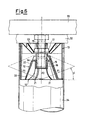
- these show an expander for table legs, indicated as a whole with 10, consisting of two elements, internal and external, joined to each other in a coaxial position with respect to a symmetry axis 11, a threaded unit which also allows the connection of an anchor plate 32 assembled to a table surface 33.
- the internal element is a truncated cone body 12 which has a threaded hole 14.
- the truncated cone body 12 is hollow with the threaded hole 14 consisting of a cylindrical portion 15, internally threaded, applied to the inside of the upper end of said truncated cone body 12.
- FIGs 1 and 2, and also 7 and 8, illustrate two embodiments of the threaded unit which utilizes its own threaded shank 16 in the threaded hole 14 of the truncated cone body 12.
- This consists of a screw-nut 17 or 117 with a widened head 18 or 118, equipped with an internal threaded portion 19 or an external threaded portion 119 for coupling with the anchor plate 32 attached to the table surface 33.
- the external lateral truncated cone wall 20 of said body 12 slopes at an angle ⁇ with respect to the symmetry axis 11.
- the external element consists of an accordion wall 13 made of elastically deformable material, such as for example, plastic material, aluminum alloys or the like, and has a structure with radial sectors separated by radial walls 23.
- Sectors 24 of the accordion wall 13 form an external cylindrical contact surface 26, which interacts with an internal surface of a hollow tubular leg 34.
- Sectors 25 of the accordion wall 13 form, on the other hand, an internal truncated cone contact surface 27, sloping at the same angle ⁇ of the truncated cone wall 20 of the truncated cone body 12 with which it is coupled.
- the external cylindrical contact surface 26 has a greater height than that of the internal truncated cone contact surface 27, the radial walls 23 having a decreasing height towards the symmetry axis 11.
- the accordion wall 13 consequently forms a concave zone 28 in the upper part of the expander 10, at the lowest point of which the sectors 25 define the outlines of a through hole 29 and a ledge-ring 30 for the widened head 18 or 118 of the screw-nut 17 or 117.
- the concave zone 28 allows interventions to be made with a suitable tool on said widened hexagonal head 18 or 118.
- the accordion wall 13 of the expander 10 can have, as in this embodiment, a longitudinal groove 31 on the external cylindrical contact surface 26, which extends for the whole height, providing said accordion wall 13 with additional elasticity.
- the single elements of the expander 10 are pre-assembled.
- the truncated cone body 12 is inserted in the accordion wall 13 and the threaded shank 16 of the screw-nut 17 or 117 is tightened until initial contact between the truncated cone surfaces 20 and 27 of said elements 12 and 13 of the expander 10, is reached.
- the pre-assembled expander 10 is then inserted into the hollow tubular leg 34.
- the truncated cone body 12 On continuously tightening the screw-nut 17 or 117, the truncated cone body 12 is forced against the internal truncated cone contact surface 27 of the accordion wall 13, and is progressively wedged into said accordion wall 13.
- the accordion wall 13 expands laterally forcing its external cylindrical contact surface 26, for the whole of its height, inside the hollow tubular leg 34.
- the vertical clamping force F2 which the threaded shrank 16 of the screw-nut 17 or 117 exerts on the threads of the hole 14 of the truncated cone body 12, is distributed as a pressure F1 perpendicular to the truncated cone walls 20 and 27 on which contact is made.
- the value of the angle ⁇ for example proposed as equal to 20°, belongs to an inclination range of 15° to 40° in which there is stability of the connection and the expander 10 can still be deformed for assembly.
- the expander for table legs 10, object of the present invention has the advantage of well tolerating the application of stress to the legs. When the expander is clamped, in fact, any possible stress applied does not cause further penetration into the accordion wall 13 of the truncated cone body 12.
Landscapes
- Tables And Desks Characterized By Structural Shape (AREA)
- Accommodation For Nursing Or Treatment Tables (AREA)
- Furniture Connections (AREA)
- Orthopedics, Nursing, And Contraception (AREA)
- Pallets (AREA)
- Finger-Pressure Massage (AREA)
Claims (9)
- Extenseur pour des pieds de table consistant en deux éléments, un interne et l'autre externe, joints dans une position coaxiale par une unité à filetage, dans lequel ledit élément interne est un corps en tronc de cône (12) possédant une surface latérale externe (20) sous la forme d'un tronc de cône, inclinée selon un angle (α) par rapport à la verticale et munie d'un trou taraudé (14), et dans lequel ledit élément externe déformable, de façon élastique, possède des surfaces de contact (26, 27) qui interagissent, de façon interne, avec la paroi en tronc de cône (20) du corps en tronc de cône (12) et de façon externe avec une surface cylindrique interne d'un pied tubulaire creux (34), dans lequel ladite inclinaison d'un angle (α) de ladite paroi latérale externe en tronc de cône (20) entre dans un intervalle d'inclinaison tel qu'il optimise la répartition des forces agissant dans l'extenseur (10) pour obtenir un compromis entre une valeur dudit angle (α) qui est suffisamment faible pour autoriser une déformation de l'extenseur (10) lors de l'assemblage et une valeur de l'angle (α) qui est suffisamment élevée pour garantir la stabilité de la connexion, de même lorsqu'un haut degré de contrainte est appliqué au pied, par conséquent sans provoquer de déplacement ultérieur du corps en tronc de cône (12), caractérisé en ce que l'élément externe consiste en une paroi en accordéon (13) avec une structure radiale par secteurs, dans laquelle des secteurs se projetant vers l'extérieur (24) forment une surface de contact non continue de forme cylindrique (26) interagissant avec une surface interne d'un pied tubulaire creux (34) et dans laquelle des secteurs se projetant vers l'intérieur (25) forment une surface de contact interne non continue en forme de tronc de cône (27) inclinée d'un angle (α), lesdits secteurs se projetant vers l'extérieur (24) et lesdits secteurs se projetant vers l'intérieur (25) étant alternés et séparés par des parois radiales (23).
- Extenseur pour pieds de table selon la revendication 1, caractérisé en ce que ledit intervalle d'inclinaison tel qu'il optimise la répartition des forces agissant dans l'extenseur (10) est identifié par l'angle (α) comme allant de 15° à 40°.
- Extenseur pour pieds de table selon la revendication 2, caractérisé en ce que l'angle (α) d'inclinaison est égal, de préférence, à 20°.
- Extenseur pour pieds de table selon la revendication 1, caractérisé en ce que le trou taraudé (14) consiste en une partie cylindrique (15), filetée de façon interne, appliquée à l'intérieur de l'extrémité supérieure du corps en tronc de cône (12).
- Extenseur pour pieds de table selon la revendication 1, caractérisé en ce que, sur la surface interne de la paroi latérale (20) du corps en tronc de cône (12), se trouvent des nervures radiales de rigidité (21).
- Extenseur pour pieds de table selon la revendication 1, caractérisé en ce que le corps en tronc de cône (12) est muni sur la surface externe de la paroi latérale (20), près de la partie supérieure dudit corps en tronc de cône (12), de reliefs (22) répartis, de façon radiale, autour du trou (14).
- Extenseur pour pieds de table selon la revendication 1, caractérisé en ce que, sur la surface externe de contact (26), se trouve une gorge longitudinale (31) s'étendant sur toute la hauteur de ladite paroi (26).
- Extenseur pour pieds de table selon la revendication 1, caractérisé en ce qu'il forme une combinaison entre un pied tubulaire creux de table (34) et un plateau de table (33) pouvant être démontés.
- Extenseur pour pieds de table selon la revendication 1, caractérisé en ce que ladite unité à filetage utilisant son corps fileté (16) dans le trou taraudé (14) du corps en tronc de cône (12) comprend une combinaison de vis et d'écrou (17, 117) avec une tête élargie (18, 118), munie d'une partie de filetage interne (19) ou d'une partie de filetage externe (119) pour un couplage avec la plaque d'ancrage (32) fixée sur le plateau de table (33).
Applications Claiming Priority (2)
| Application Number | Priority Date | Filing Date | Title |
|---|---|---|---|
| ITMI002519 | 2000-11-23 | ||
| IT2000MI002519A IT1319124B1 (it) | 2000-11-23 | 2000-11-23 | Espansore per gamba di tavolo |
Publications (3)
| Publication Number | Publication Date |
|---|---|
| EP1208767A2 EP1208767A2 (fr) | 2002-05-29 |
| EP1208767A3 EP1208767A3 (fr) | 2002-08-14 |
| EP1208767B1 true EP1208767B1 (fr) | 2004-01-28 |
Family
ID=11446133
Family Applications (1)
| Application Number | Title | Priority Date | Filing Date |
|---|---|---|---|
| EP01204450A Expired - Lifetime EP1208767B1 (fr) | 2000-11-23 | 2001-11-19 | Expendeur pour pied de table |
Country Status (6)
| Country | Link |
|---|---|
| EP (1) | EP1208767B1 (fr) |
| AT (1) | ATE258400T1 (fr) |
| DE (1) | DE60101888T2 (fr) |
| DK (1) | DK1208767T3 (fr) |
| ES (1) | ES2215107T3 (fr) |
| IT (1) | IT1319124B1 (fr) |
Families Citing this family (1)
| Publication number | Priority date | Publication date | Assignee | Title |
|---|---|---|---|---|
| ITVI20060309A1 (it) | 2006-10-20 | 2008-04-21 | Nardi S P A | Elemento di accoppiamento per gambe di tavoli |
Family Cites Families (5)
| Publication number | Priority date | Publication date | Assignee | Title |
|---|---|---|---|---|
| FR1218986A (fr) * | 1959-03-19 | 1960-05-13 | Fixation rapide et démontable de pied métallique pour tables ou autres applications | |
| US3063765A (en) * | 1959-10-12 | 1962-11-13 | Louis A Welt | Furniture leg positioning and mounting assembly |
| DE2155234A1 (de) * | 1971-11-06 | 1973-05-10 | Rolf Voelkle | Nach dem baukastenprinzip zusammensetzbares gestell |
| IT244138Y1 (it) * | 1998-07-17 | 2002-03-07 | Leonardo Srl | Dispositivo perfezionato per collegare una gamba ad un piano di untavolo |
| US6446313B2 (en) * | 1999-03-26 | 2002-09-10 | Joel W. Pfister | Mechanical locking connector |
-
2000
- 2000-11-23 IT IT2000MI002519A patent/IT1319124B1/it active
-
2001
- 2001-11-19 DK DK01204450T patent/DK1208767T3/da active
- 2001-11-19 ES ES01204450T patent/ES2215107T3/es not_active Expired - Lifetime
- 2001-11-19 AT AT01204450T patent/ATE258400T1/de active
- 2001-11-19 DE DE60101888T patent/DE60101888T2/de not_active Expired - Lifetime
- 2001-11-19 EP EP01204450A patent/EP1208767B1/fr not_active Expired - Lifetime
Also Published As
| Publication number | Publication date |
|---|---|
| ES2215107T3 (es) | 2004-10-01 |
| DK1208767T3 (da) | 2004-06-07 |
| ITMI20002519A1 (it) | 2002-05-23 |
| IT1319124B1 (it) | 2003-09-23 |
| DE60101888D1 (de) | 2004-03-04 |
| DE60101888T2 (de) | 2004-12-30 |
| ATE258400T1 (de) | 2004-02-15 |
| EP1208767A2 (fr) | 2002-05-29 |
| EP1208767A3 (fr) | 2002-08-14 |
Similar Documents
| Publication | Publication Date | Title |
|---|---|---|
| US5037259A (en) | Nut with sleeve lock | |
| US5106225A (en) | Adjustable spacer | |
| US5881653A (en) | Shelf assembly system | |
| JP5247713B2 (ja) | 拡張スペーサ | |
| EP3683455B1 (fr) | Connecteur expansible | |
| US20070258786A1 (en) | Rivet-like fastener with floating nut | |
| US3910155A (en) | Jam together fastener | |
| US7229230B2 (en) | Tube connectors | |
| AU2013201398A1 (en) | Wooden member joint structure | |
| IE48537B1 (en) | An anchoring bolt | |
| EP1208767B1 (fr) | Expendeur pour pied de table | |
| HU209187B (en) | Tightening wedge | |
| JP2020020372A (ja) | ブラインドボルト | |
| KR20000076243A (ko) | 해체 가능한 앵커용 다품 다월 | |
| EP0343342B1 (fr) | Elément de fixation avec un manchon extensible | |
| US20220056938A1 (en) | Dowel fasteners | |
| US20080038079A1 (en) | Adjustable concrete drop-in anchor | |
| JP4484319B2 (ja) | 脚端具取付構造 | |
| GB2190164A (en) | Anchoring device | |
| JPS59222614A (ja) | 半径方向に膨脹可能な留め具 | |
| US5094561A (en) | Compressing assembly for a supporting device | |
| JPH058333Y2 (fr) | ||
| GB2044876A (en) | Fastening means | |
| JP3058521B2 (ja) | 床パネル支持構造 | |
| EP1211429A1 (fr) | Ancrage multi-usage pour pieds de table |
Legal Events
| Date | Code | Title | Description |
|---|---|---|---|
| PUAI | Public reference made under article 153(3) epc to a published international application that has entered the european phase |
Free format text: ORIGINAL CODE: 0009012 |
|
| AK | Designated contracting states |
Kind code of ref document: A2 Designated state(s): AT BE CH CY DE DK ES FI FR GB GR IE IT LI LU MC NL PT SE TR |
|
| AX | Request for extension of the european patent |
Free format text: AL;LT;LV;MK;RO;SI |
|
| PUAL | Search report despatched |
Free format text: ORIGINAL CODE: 0009013 |
|
| AK | Designated contracting states |
Kind code of ref document: A3 Designated state(s): AT BE CH CY DE DK ES FI FR GB GR IE IT LI LU MC NL PT SE TR |
|
| AX | Request for extension of the european patent |
Free format text: AL;LT;LV;MK;RO;SI |
|
| 17P | Request for examination filed |
Effective date: 20030212 |
|
| 17Q | First examination report despatched |
Effective date: 20030306 |
|
| AKX | Designation fees paid |
Designated state(s): AT BE CH CY DE DK ES FI FR GB GR IE IT LI LU MC NL PT SE TR |
|
| AXX | Extension fees paid |
Extension state: SI Payment date: 20030212 |
|
| GRAP | Despatch of communication of intention to grant a patent |
Free format text: ORIGINAL CODE: EPIDOSNIGR1 |
|
| GRAS | Grant fee paid |
Free format text: ORIGINAL CODE: EPIDOSNIGR3 |
|
| GRAA | (expected) grant |
Free format text: ORIGINAL CODE: 0009210 |
|
| AK | Designated contracting states |
Kind code of ref document: B1 Designated state(s): AT BE CH CY DE DK ES FI FR GB GR IE IT LI LU MC NL PT SE TR |
|
| AX | Request for extension of the european patent |
Extension state: SI |
|
| PG25 | Lapsed in a contracting state [announced via postgrant information from national office to epo] |
Ref country code: LI Free format text: LAPSE BECAUSE OF FAILURE TO SUBMIT A TRANSLATION OF THE DESCRIPTION OR TO PAY THE FEE WITHIN THE PRESCRIBED TIME-LIMIT Effective date: 20040128 Ref country code: CY Free format text: LAPSE BECAUSE OF FAILURE TO SUBMIT A TRANSLATION OF THE DESCRIPTION OR TO PAY THE FEE WITHIN THE PRESCRIBED TIME-LIMIT Effective date: 20040128 Ref country code: CH Free format text: LAPSE BECAUSE OF FAILURE TO SUBMIT A TRANSLATION OF THE DESCRIPTION OR TO PAY THE FEE WITHIN THE PRESCRIBED TIME-LIMIT Effective date: 20040128 Ref country code: BE Free format text: LAPSE BECAUSE OF FAILURE TO SUBMIT A TRANSLATION OF THE DESCRIPTION OR TO PAY THE FEE WITHIN THE PRESCRIBED TIME-LIMIT Effective date: 20040128 Ref country code: TR Free format text: LAPSE BECAUSE OF FAILURE TO SUBMIT A TRANSLATION OF THE DESCRIPTION OR TO PAY THE FEE WITHIN THE PRESCRIBED TIME-LIMIT Effective date: 20040128 Ref country code: NL Free format text: LAPSE BECAUSE OF FAILURE TO SUBMIT A TRANSLATION OF THE DESCRIPTION OR TO PAY THE FEE WITHIN THE PRESCRIBED TIME-LIMIT Effective date: 20040128 |
|
| REG | Reference to a national code |
Ref country code: GB Ref legal event code: FG4D |
|
| REG | Reference to a national code |
Ref country code: CH Ref legal event code: EP |
|
| REG | Reference to a national code |
Ref country code: IE Ref legal event code: FG4D |
|
| REF | Corresponds to: |
Ref document number: 60101888 Country of ref document: DE Date of ref document: 20040304 Kind code of ref document: P |
|
| PG25 | Lapsed in a contracting state [announced via postgrant information from national office to epo] |
Ref country code: SE Free format text: LAPSE BECAUSE OF FAILURE TO SUBMIT A TRANSLATION OF THE DESCRIPTION OR TO PAY THE FEE WITHIN THE PRESCRIBED TIME-LIMIT Effective date: 20040428 |
|
| REG | Reference to a national code |
Ref country code: GR Ref legal event code: EP Ref document number: 20040401271 Country of ref document: GR |
|
| REG | Reference to a national code |
Ref country code: DK Ref legal event code: T3 |
|
| NLV1 | Nl: lapsed or annulled due to failure to fulfill the requirements of art. 29p and 29m of the patents act | ||
| REG | Reference to a national code |
Ref country code: CH Ref legal event code: PL |
|
| REG | Reference to a national code |
Ref country code: ES Ref legal event code: FG2A Ref document number: 2215107 Country of ref document: ES Kind code of ref document: T3 |
|
| ET | Fr: translation filed | ||
| PG25 | Lapsed in a contracting state [announced via postgrant information from national office to epo] |
Ref country code: IE Free format text: LAPSE BECAUSE OF NON-PAYMENT OF DUE FEES Effective date: 20041119 Ref country code: LU Free format text: LAPSE BECAUSE OF NON-PAYMENT OF DUE FEES Effective date: 20041119 |
|
| PG25 | Lapsed in a contracting state [announced via postgrant information from national office to epo] |
Ref country code: MC Free format text: LAPSE BECAUSE OF NON-PAYMENT OF DUE FEES Effective date: 20041130 |
|
| PLBE | No opposition filed within time limit |
Free format text: ORIGINAL CODE: 0009261 |
|
| STAA | Information on the status of an ep patent application or granted ep patent |
Free format text: STATUS: NO OPPOSITION FILED WITHIN TIME LIMIT |
|
| 26N | No opposition filed |
Effective date: 20041029 |
|
| REG | Reference to a national code |
Ref country code: IE Ref legal event code: MM4A |
|
| PG25 | Lapsed in a contracting state [announced via postgrant information from national office to epo] |
Ref country code: PT Free format text: LAPSE BECAUSE OF NON-PAYMENT OF DUE FEES Effective date: 20040628 |
|
| REG | Reference to a national code |
Ref country code: DE Ref legal event code: R082 Ref document number: 60101888 Country of ref document: DE Representative=s name: HOEGER, STELLRECHT & PARTNER PATENTANWAELTE MB, DE |
|
| REG | Reference to a national code |
Ref country code: FR Ref legal event code: PLFP Year of fee payment: 15 |
|
| REG | Reference to a national code |
Ref country code: FR Ref legal event code: PLFP Year of fee payment: 16 |
|
| REG | Reference to a national code |
Ref country code: FR Ref legal event code: PLFP Year of fee payment: 17 |
|
| REG | Reference to a national code |
Ref country code: DE Ref legal event code: R082 Ref document number: 60101888 Country of ref document: DE Representative=s name: HOEGER, STELLRECHT & PARTNER PATENTANWAELTE MB, DE |
|
| PGFP | Annual fee paid to national office [announced via postgrant information from national office to epo] |
Ref country code: ES Payment date: 20201201 Year of fee payment: 20 Ref country code: FI Payment date: 20201125 Year of fee payment: 20 Ref country code: DE Payment date: 20201127 Year of fee payment: 20 Ref country code: FR Payment date: 20201125 Year of fee payment: 20 Ref country code: GR Payment date: 20201127 Year of fee payment: 20 Ref country code: AT Payment date: 20201103 Year of fee payment: 20 Ref country code: GB Payment date: 20201127 Year of fee payment: 20 Ref country code: IT Payment date: 20201123 Year of fee payment: 20 Ref country code: DK Payment date: 20201125 Year of fee payment: 20 |
|
| REG | Reference to a national code |
Ref country code: DE Ref legal event code: R071 Ref document number: 60101888 Country of ref document: DE |
|
| REG | Reference to a national code |
Ref country code: DK Ref legal event code: EUP Expiry date: 20211119 |
|
| REG | Reference to a national code |
Ref country code: GB Ref legal event code: PE20 Expiry date: 20211118 |
|
| REG | Reference to a national code |
Ref country code: FI Ref legal event code: MAE |
|
| REG | Reference to a national code |
Ref country code: AT Ref legal event code: MK07 Ref document number: 258400 Country of ref document: AT Kind code of ref document: T Effective date: 20211119 |
|
| PG25 | Lapsed in a contracting state [announced via postgrant information from national office to epo] |
Ref country code: GB Free format text: LAPSE BECAUSE OF EXPIRATION OF PROTECTION Effective date: 20211118 |
|
| REG | Reference to a national code |
Ref country code: ES Ref legal event code: FD2A Effective date: 20220225 |
|
| PG25 | Lapsed in a contracting state [announced via postgrant information from national office to epo] |
Ref country code: ES Free format text: LAPSE BECAUSE OF EXPIRATION OF PROTECTION Effective date: 20211120 |