EP1208816A2 - Hydraulisches Stenteinbringungssystem - Google Patents
Hydraulisches Stenteinbringungssystem Download PDFInfo
- Publication number
- EP1208816A2 EP1208816A2 EP01124605A EP01124605A EP1208816A2 EP 1208816 A2 EP1208816 A2 EP 1208816A2 EP 01124605 A EP01124605 A EP 01124605A EP 01124605 A EP01124605 A EP 01124605A EP 1208816 A2 EP1208816 A2 EP 1208816A2
- Authority
- EP
- European Patent Office
- Prior art keywords
- stent
- catheter
- sheath
- receiving chamber
- containment sheath
- Prior art date
- Legal status (The legal status is an assumption and is not a legal conclusion. Google has not performed a legal analysis and makes no representation as to the accuracy of the status listed.)
- Granted
Links
- 239000012530 fluid Substances 0.000 claims abstract description 111
- 125000006850 spacer group Chemical group 0.000 claims abstract description 45
- 239000000463 material Substances 0.000 claims abstract description 28
- 230000014759 maintenance of location Effects 0.000 claims abstract description 22
- 238000007789 sealing Methods 0.000 claims abstract description 9
- 238000000034 method Methods 0.000 claims description 11
- 238000004891 communication Methods 0.000 claims description 2
- 238000003780 insertion Methods 0.000 abstract description 5
- 230000037431 insertion Effects 0.000 abstract description 5
- 230000009977 dual effect Effects 0.000 abstract description 3
- 208000002223 abdominal aortic aneurysm Diseases 0.000 description 14
- 238000004804 winding Methods 0.000 description 13
- 230000008439 repair process Effects 0.000 description 12
- 210000000709 aorta Anatomy 0.000 description 11
- 206010002329 Aneurysm Diseases 0.000 description 10
- 208000007474 aortic aneurysm Diseases 0.000 description 9
- 238000001356 surgical procedure Methods 0.000 description 5
- 230000003187 abdominal effect Effects 0.000 description 4
- 230000007704 transition Effects 0.000 description 4
- 238000013459 approach Methods 0.000 description 3
- 239000008280 blood Substances 0.000 description 3
- 210000004369 blood Anatomy 0.000 description 3
- 238000010276 construction Methods 0.000 description 3
- 230000007547 defect Effects 0.000 description 3
- 208000004717 Ruptured Aneurysm Diseases 0.000 description 2
- 210000001367 artery Anatomy 0.000 description 2
- 230000034994 death Effects 0.000 description 2
- 231100000517 death Toxicity 0.000 description 2
- 230000010339 dilation Effects 0.000 description 2
- 210000001105 femoral artery Anatomy 0.000 description 2
- 238000003384 imaging method Methods 0.000 description 2
- 208000014674 injury Diseases 0.000 description 2
- 230000001575 pathological effect Effects 0.000 description 2
- 210000002254 renal artery Anatomy 0.000 description 2
- 230000008733 trauma Effects 0.000 description 2
- 201000001320 Atherosclerosis Diseases 0.000 description 1
- 0 CCCC(C*)N Chemical compound CCCC(C*)N 0.000 description 1
- 206010010356 Congenital anomaly Diseases 0.000 description 1
- 206010020772 Hypertension Diseases 0.000 description 1
- 206010061218 Inflammation Diseases 0.000 description 1
- 229920002614 Polyether block amide Polymers 0.000 description 1
- 208000035965 Postoperative Complications Diseases 0.000 description 1
- 235000011449 Rosa Nutrition 0.000 description 1
- 208000027418 Wounds and injury Diseases 0.000 description 1
- 210000001015 abdomen Anatomy 0.000 description 1
- 210000000683 abdominal cavity Anatomy 0.000 description 1
- 230000032683 aging Effects 0.000 description 1
- 230000004323 axial length Effects 0.000 description 1
- 238000005452 bending Methods 0.000 description 1
- 230000008859 change Effects 0.000 description 1
- 230000001419 dependent effect Effects 0.000 description 1
- 230000000994 depressogenic effect Effects 0.000 description 1
- 238000011161 development Methods 0.000 description 1
- 230000018109 developmental process Effects 0.000 description 1
- 230000003292 diminished effect Effects 0.000 description 1
- 238000011156 evaluation Methods 0.000 description 1
- 210000004013 groin Anatomy 0.000 description 1
- 210000003090 iliac artery Anatomy 0.000 description 1
- 238000002513 implantation Methods 0.000 description 1
- 208000015181 infectious disease Diseases 0.000 description 1
- 230000004054 inflammatory process Effects 0.000 description 1
- 238000002347 injection Methods 0.000 description 1
- 239000007924 injection Substances 0.000 description 1
- 238000011835 investigation Methods 0.000 description 1
- 210000005240 left ventricle Anatomy 0.000 description 1
- 210000004072 lung Anatomy 0.000 description 1
- 238000013160 medical therapy Methods 0.000 description 1
- 239000002184 metal Substances 0.000 description 1
- 238000013508 migration Methods 0.000 description 1
- 230000005012 migration Effects 0.000 description 1
- 238000012986 modification Methods 0.000 description 1
- 230000004048 modification Effects 0.000 description 1
- HLXZNVUGXRDIFK-UHFFFAOYSA-N nickel titanium Chemical compound [Ti].[Ti].[Ti].[Ti].[Ti].[Ti].[Ti].[Ti].[Ti].[Ti].[Ti].[Ni].[Ni].[Ni].[Ni].[Ni].[Ni].[Ni].[Ni].[Ni].[Ni].[Ni].[Ni].[Ni].[Ni] HLXZNVUGXRDIFK-UHFFFAOYSA-N 0.000 description 1
- 229910001000 nickel titanium Inorganic materials 0.000 description 1
- 210000000056 organ Anatomy 0.000 description 1
- 230000002093 peripheral effect Effects 0.000 description 1
- 229920000642 polymer Polymers 0.000 description 1
- 210000001147 pulmonary artery Anatomy 0.000 description 1
- 230000002685 pulmonary effect Effects 0.000 description 1
- 238000011084 recovery Methods 0.000 description 1
- 238000007790 scraping Methods 0.000 description 1
- 238000011272 standard treatment Methods 0.000 description 1
Images



Classifications
-
- A—HUMAN NECESSITIES
- A61—MEDICAL OR VETERINARY SCIENCE; HYGIENE
- A61F—FILTERS IMPLANTABLE INTO BLOOD VESSELS; PROSTHESES; DEVICES PROVIDING PATENCY TO, OR PREVENTING COLLAPSING OF, TUBULAR STRUCTURES OF THE BODY, e.g. STENTS; ORTHOPAEDIC, NURSING OR CONTRACEPTIVE DEVICES; FOMENTATION; TREATMENT OR PROTECTION OF EYES OR EARS; BANDAGES, DRESSINGS OR ABSORBENT PADS; FIRST-AID KITS
- A61F2/00—Filters implantable into blood vessels; Prostheses, i.e. artificial substitutes or replacements for parts of the body; Appliances for connecting them with the body; Devices providing patency to, or preventing collapsing of, tubular structures of the body, e.g. stents
- A61F2/95—Instruments specially adapted for placement or removal of stents or stent-grafts
-
- A—HUMAN NECESSITIES
- A61—MEDICAL OR VETERINARY SCIENCE; HYGIENE
- A61F—FILTERS IMPLANTABLE INTO BLOOD VESSELS; PROSTHESES; DEVICES PROVIDING PATENCY TO, OR PREVENTING COLLAPSING OF, TUBULAR STRUCTURES OF THE BODY, e.g. STENTS; ORTHOPAEDIC, NURSING OR CONTRACEPTIVE DEVICES; FOMENTATION; TREATMENT OR PROTECTION OF EYES OR EARS; BANDAGES, DRESSINGS OR ABSORBENT PADS; FIRST-AID KITS
- A61F2/00—Filters implantable into blood vessels; Prostheses, i.e. artificial substitutes or replacements for parts of the body; Appliances for connecting them with the body; Devices providing patency to, or preventing collapsing of, tubular structures of the body, e.g. stents
- A61F2/95—Instruments specially adapted for placement or removal of stents or stent-grafts
- A61F2/962—Instruments specially adapted for placement or removal of stents or stent-grafts having an outer sleeve
- A61F2/966—Instruments specially adapted for placement or removal of stents or stent-grafts having an outer sleeve with relative longitudinal movement between outer sleeve and prosthesis, e.g. using a push rod
-
- A—HUMAN NECESSITIES
- A61—MEDICAL OR VETERINARY SCIENCE; HYGIENE
- A61F—FILTERS IMPLANTABLE INTO BLOOD VESSELS; PROSTHESES; DEVICES PROVIDING PATENCY TO, OR PREVENTING COLLAPSING OF, TUBULAR STRUCTURES OF THE BODY, e.g. STENTS; ORTHOPAEDIC, NURSING OR CONTRACEPTIVE DEVICES; FOMENTATION; TREATMENT OR PROTECTION OF EYES OR EARS; BANDAGES, DRESSINGS OR ABSORBENT PADS; FIRST-AID KITS
- A61F2/00—Filters implantable into blood vessels; Prostheses, i.e. artificial substitutes or replacements for parts of the body; Appliances for connecting them with the body; Devices providing patency to, or preventing collapsing of, tubular structures of the body, e.g. stents
- A61F2/95—Instruments specially adapted for placement or removal of stents or stent-grafts
- A61F2/962—Instruments specially adapted for placement or removal of stents or stent-grafts having an outer sleeve
- A61F2/966—Instruments specially adapted for placement or removal of stents or stent-grafts having an outer sleeve with relative longitudinal movement between outer sleeve and prosthesis, e.g. using a push rod
- A61F2002/9665—Instruments specially adapted for placement or removal of stents or stent-grafts having an outer sleeve with relative longitudinal movement between outer sleeve and prosthesis, e.g. using a push rod with additional retaining means
Definitions
- This invention relates to the field of stents, and more particularly to the field of the delivery and deployment of self-expanding stent grafts.
- the aorta is the main artery of the body, arising from the base of the left ventricle of the heart It is a large vessel, about one inch in diameter, with thick, elastic walls to withstand the changes in pressure as the heart beats. It supplies oxygenated blood to all arteries except the pulmonary artery (which carries blood to the lungs to be oxygenated.
- the aorta curves behind the heart and down the chest into the abdomen, where it divides into the two iliac arteries.
- a pathologic dilation or balloon like enlargement of the aorta below the renal arteries may occur as a consequence of aging, atherosclerosis, infection, inflammation, trauma, congenital anomalies, or other pathologic conditions.
- Localized dilation of the aorta below the renal arteries to a diameter 50 percent greater than the expected normal diameter is known as abdominal aortic aneurysm, or AAA.
- abdominal aortic aneurysm or AAA.
- aneurysms grow gradually over time, increasing by an average of two to three millimeters annually. It can take 10 to 15 years for an aneurysm to reach a size at which surgery is deemed necessary. Surgical repair of abdominal aortic aneurysm is indicated when the risk of rupture is believed to exceed the risk associated with open surgery.
- the risk of rupture increases with the size of the aneurysm. Due to the high risk of rupture for abdominal aortic aneurysms greater than 5 cm and the mortality associated with rupture, surgical repair of such aneurysms is the standard of care. At 5 to 6 cm, the risk of rupture increases by 20 percent per year.
- Abdominal aortic aneurysm is the 13th leading cause of death in the United States accounting for more than 16,000 deaths annually. More than 40,000 procedures to treat abdominal aortic aneurysms are performed in the United States annually with approximately 32,000 new patients diagnosed with unruptured aneurysms each year. Of those diagnosed patients, 24,000 were over the age of 65. More than two million people are estimated to have an undiagnosed abdominal aortic aneurysm. Over the past 40 years, the prevalence of abdominal aortic aneurysm has risen three-fold.
- abdominal aortic aneurysms are asymptomatic and are often discovered only as a result of investigation of other medical problems.
- the primary risk posed by an abdominal aortic aneurysm is its propensity to rupture.
- Emergent surgical repair of a ruptured aneurysm has a high risk (40 to 50 percent) of perioperative mortality.
- Elective aneurysm repair by contrast, has an associated mortality risk of 1 to 5 percent. Up to 5096 of patients with untreated aneurysms die of rupture in a 5-year period.
- the surgeon makes a large midline incision (8 to 10 inches) exposing the entire abdominal cavity, including the aorta and other organs.
- the bowel is retracted from the operative field and the aorta is visually examined to determine the proper size and configuration of the synthetic graft that will be used to replace the diseased vessel. If the iliacs are involved or if there is not an adequate amount of healthy aorta distal to the graft, then a bifurcated graft is utilized.
- the aorta or the aorta and iliacs are cross-clamped proximal and distal to the aneurysm for a period of 30 to 90 minutes and the diseased section is replaced by a prosthetic graft by suture.
- the wall of the aorta is wrapped and sewn around the graft to protect it.
- the incision site is then closed with sutures and staples.
- the open surgery procedure can take up to four hours to perform and has significant morbidity rates in 15 to 30 percent of patients.
- the average hospital stay associated with open abdominal repair is seven to twelve days, including time spent in the ICU. Patient recovery time can last three months.
- Mortality rates for the surgical repair of non-ruptured aneurysms from multicenter reports have a range of 3-5% and at approximately 7% in population based studies.
- endovascular repair provides essentially the same treatment as open abdominal repair, but via a different access route.
- the surgeon begins by making small incisions above the femoral arteries in the groin area of each leg. Using catheters, the interventional physician then inserts the stent graft through the femoral artery and precisely places the graft at the appropriate anatomical location. The graft is secured into place by the self-expansion of the nitinol stent rings. This seals off the distended portion of the aorta from circulation.
- the first commercially available endoluminal graft was implanted in the early 1990s. This early tube graft was applicable to only 5 to 10 percent of patients with abdominal aortic aneurysm due to anatomical considerations. Subsequent technological innovations have included the development of a bifurcated stent graft and improvements in delivery systems, which expand applicability to 40 percent of patients with abdominal aortic aneurysm.
- endoluminal grafts generally has required a team approach, the team may include a cardiologist, surgeon, radiologist, and support staff. More extensive pre-case evaluation is required than with open surgical repair due to necessary considerations such as endovascular access, implantation sites and morphology of the aneurysm. Proper patient selection and customization of the endoluminal graft require careful pre-procedural imaging to address these anatomical requirements. In addition, the surgeon must be trained in the use of guidewires, catheters and imaging modalities.
- the endovascular procedure Compared to open surgery, the endovascular procedure provides substantial patient benefits such as reduced trauma from the surgery, shorter hospital stay, shorter intensive care unit stay, less blood loss, and fewer postoperative complications such as pulmonary compromise.
- stent/stent graft systems One problem with presently available stent/stent graft systems lies in the delivery and deployment of the stent/stent graft. Typically a series of interfitting catheters and tubes are provided to push or otherwise move the stent graft from the catheter and allow it to be deployed. In practice, the use of such a "push-pull" type system is less than ideal. Physicians have indicated a better delivery and deployment approach would be desired.
- the present invention addresses the problems relating to stent delivery and deployment through the use of a retraction section which permits the use of at least two different materials to be used for the stent containment portion and the stent retraction section of the stent containment sheath of a stent/stent-graft delivery system.
- a stent retraction section for the efficient retraction of the containment sheath an anti kinking spacer is used to prevent the surrounding containment sheath from kinking and binding.
- the anti kinking spacer can be made of a weak closely wound helical spring and alternatively the cross section of individual windings of the spring can be tapered to be thick near the central axis and thinner near the perimeter edge.
- a device according to an embodiment of the invention uses fluid pressure within a catheter to retract a stent graft containment sheath to thereby allow the delivery of a stent graft.
- a hydraulic stent or stent graft delivery system which utilizes at least two different structural materials to effectuate the easy retention and release of the stent and stent graft, while maintaining structural and sealing integrity for a pressurizable fluid chamber.
- An anti kinking spacer is disclosed which prevents buckling/kinking of the otherwise unsupported sheath containment section when the catheter assembly is bent such as for insertion a movement to the delivery site.
- a configuration according to an embodiment of the invention provides a flexible small or dual diameter delivery system that uses fluid pressure within the catheter to retract the stent/stent graft containment sheath and allow the delivery and deployment of the stent/stent graft.
- Figure 1 is a view of a stent graft system according to an embodiment of the present invention in which the stent graft is not deployed.
- the system 30 preferably features a source of pressurized fluid, such as a syringe 32, coupled to the catheter body 34 through a Y-type fitting 38.
- the catheter body 34 is used typically over a guidewire 40.
- the guidewire 40 may not always be needed or desired to use the system shown.
- the distal section 42 of catheter body 34 features a backstop 50.
- the backstop 50 is fixed to the catheter body 34 so as to limit travel of the containment sheath 52.
- containment sheath 52 may be positioned about and towards the distal end 42 of the catheter body 34.
- proximal taper 54 At the proximal end of containment sheath is proximal taper 54.
- Proximal taper 54 permits the relatively larger diameter containment sheath to be moved within a patient's body, while minimizing the likelihood of sharp edges catching and damaging tissue.
- Proximal taper 54 further is preferably designed so as to be able to engage against backstop 50, so as to thereby limit the further proximal movement of containment sheath 52, as will be described below.
- distal nose 56 Positioned distal to the containment sheath 52 is distal nose 56.
- the distal nose 56 is fixed to the catheter body 34 and functions to act as the distal cover of the distal edge of containment sheath 52.
- the distal nose 56 also permits the relatively larger diameter containment sheath to be moved within a patient's body, while minimizing the likelihood of sharp edges catching and damaging tissue.
- FIG 2 is a view of a stent graft system of Figure 1, in which the stent graft has been deployed.
- the syringe plunger has been depressed so as to force fluid from the syringe into the catheter and into a fluid delivery chamber (described in detail below).
- a fluid delivery chamber (described in detail below).
- Such an introduction of fluid causes the containment sheath 52 to move proximally, in proximal direction shown by the arrow 64, so as to ultimately abut against backstop 50.
- This movement causes the containment sheath 52 to no longer contain a stent graft 60 formerly contained therein.
- the containment sheath 52 is moved to a location equal to or beyond the stent cup plunger 66.
- Stent cup plunger 66 is a ring type structure engaged with the catheter body 34 and is sized to snugly fit within the containment sheath 52 wherein the stent cup plunger 52 acts as the end surface of the anti kink spacer which as the spacer coils are compressed and contact one another and become inflexible establishes a limit for the movement in the proximal direction by the stent graft 60 as the containment sheath 52 is moved in the proximal direction 64.
- Stent graft 60 discussed may be any self expanding stent or stent graft sized to be released from a complimentarily sized containment sheath, although in one embodiment the stent graft comprises a Talent» stent graft, available from Medtronic AVE, Sunrise, Florida, a division of Medtronic AVE, Santa Rosa, California.
- pressurized fluid directed toward a fluid receiving chamber within a system of fluid seals between the containment sheath 52 and the catheter 34 is used to move the containment sheath 52 in the proximal direction 64.
- the pressurization limits of the fluid receiving chamber are described below.
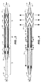
- Figure 3 is a detailed sectional view of the distal end of the stent graft system showing the contents of the containment sheath 52 of the stent graft system 30 which includes the fluid receiving chamber.
- the containment sheath 52 and proximal taper 54 preferably have a movable seal mount 71 fixed thereto.
- the moveable seal mount 71 may include an end wall and series of two peripheral ridges configured and is sized in this embodiment to mount, receive, and retain two side by side O-rings which form the second or movable fluid seals 70.
- the fluid seals as described therein can also be lip seals or other seal configurations compatible with sealing between substantially circular cylinders as the catheter 34 outer surface and the inner surface of the fluid receiving chamber and a sheath retraction section 80 inner surface of the containment sheath 52.
- the movable seal mount 71 causes the O-rings of the movable seal 71 to move with the containment sheath 52 as it moves along the catheter 34 when the fluid receiving chamber is pressurized.
- the movable fluid seals 70 are dimensioned to provide a fluid tight seal with catheter body 34 while still permitting sliding movement with respect to the catheter body 34.
- the catheter body 34 may have a set of fixed (first) fluid seals 72 fixed to a fixed seal mount 73; where the fixed fluid seals 72 provide a fluid tight seal with the inside surface of the containment sheath 52 while still permitting sliding movement with the catheter body 34.
- the movable and fixed fluid seals 70, 72 define a fluid receiving chamber 75 therebetween. Located between the movable 70 and fixed 71 seals within fluid receiving chamber 22 is a fluid opening 76.
- the backstop may ensure that the fluid receiving chamber 75, which receives pressurized fluid, will not be exposed to body tissues directly. That is the pressurized fluid within fluid receiving chamber 75 will not be exposed to body tissues directly.
- the backstop 50 be positioned along catheter body 34 so as to limit the proximal movement of containment sheath 52 such that fluid within the fluid receiving chamber will not be exposed to body tissue, while permitting sufficient movement such that the containment sheath 52 moves to permit full deployment of the stent graft 60.
- the containment sheath can be configured with a continuous single diameter from end to end. However, the material of the sheath can be different in different sections of the sheath.
- a stent retraction portion of the sheath adjacent to the compressed stent retention section 78 may be constructed of a material having a lubricious inner surface having a low coefficient of friction so the stent graft 60 contained therein slides easily out during deployment as the sheath 52 is retracted.
- a material of the stent retraction portion of the sheath 52 having the desired frictional qualities has been generally found to be soft and susceptible to scoring and the creation of surface irregularities as the containment sheath 52 is retracted and the stent graft 60 is deployed.
- an intermediate section identified a stent retraction portion of the containment sheath 52 (initially positioned adjacent to a sheath retraction section 80 of the catheter body 34 can be made of a material whose surface is less susceptible to scoring and the introduction of other surface defects than the softer surface finish material of the stent retention portion.
- the stent cup plunger 66 acts as the end of a block (anchored by the fixed seal mount through the anti kinking spacer) which prevents the stent graft 60 from moving proximally.
- the distal portion of the stent graft assembly were severely bent prior to or during deployment of the stent graft, it is possible that the unreinforced tubular wall structure of the stent retraction portion of the containment sheath 52, corresponding the sheath retraction section 80 of the catheter body 34 may buckle or kink. Such a buckling or kinking could create surface irregularities due to the migration of material , were plastic deformation to occur, even if the catheter was to subsequently be straightened out.
- a anti kinking spacer 82 is preferably provided around the sheath retraction section 80 of the catheter body 34 and within the stent retraction portion of the containment sheath 52 to maintain the radial spacing between the two.
- the anti kinking spacer 82 is in one embodiment a weak helical spring having the weak axial qualities similar to the well known children's toy known as a Slinky® (e.g., as shown in Figure 7). While not preferred it could be a simply thick cross section helical spring.
- a weak helical spring having the weak axial qualities similar to the well known children's toy known as a Slinky® (e.g., as shown in Figure 7). While not preferred it could be a simply thick cross section helical spring.
- Another configuration of the spacer is shown in Figure 8, where the cross sectional thickness of the individual windings is a tapered section 84, where the thickness closer to the central axis of the spacer is thicker 85 with a thinner 86 section thickness farther away from the central axis of the spacer.
- the gap between the inside of the containment sheath 52 and the radial edge of the spacer 82 is about 0.030-0.040" (0.762-1.016 mm), however since the spacer is weak and flexible this radial gap may be considered a total radial gap which varies between the inside the outside edge of the spacer in the radial direction (the inside edge gap being between the catheter body 34 and the inside edge of the spacer.
- the diameter of the catheter is typically 7 French, while the diameter of the containment section is in the range of 18-25 French.
- the spacer can also be a stack of washers which are loosely positioned around the sheath retraction section 80 of the catheter body 34, or the spacer can be a series of washer like or helical ribs in a flexible liner material, such as an annular bellows structure, but without the requirement of pressure containment, though a pressurized annular structure might also be used, but would not provide the assurance of kink resistance that washer and helical structures do.
- Figure 4 shows the stent graft 60 of Figure 3 with the containment sheath 52 in a fully retracted position.
- the proximal edge of stent containment portion of the containment sheath 52 has reached the location of the stent cup plunger 66, but has not been retracted by it so that the anti kink spacer 82 (which may be made of an injection molded polymer rather that a metal as would usually be expected) is directly exposed to the deployment surroundings. This prevents dislodgment of the spacer and exposure of the edges of the stent cup plunger 66 to the surrounding tissue, which could act as a scraping surface were they to be exposed.
- the containment sheath 52 is fully retracted into interference with the backstop 50.
- Cross sections 11-11 and 12-12 are taken through the fluid receiving opening and the anti kinking spacer 82 shown here.
- Figure 5 is an alternate embodiment of the invention having a containment sheath 53 where the diameter of the retraction portion surrounding the antikinking spacer 82 and the fluid receiving chamber section 74 are a smaller diameter (e.g., 10-12 Fr) to more maneuverable during insertion and positioning and removal, while the stent retention portion of the containment section is larger to contain the stent graft 61.
- the fluid receiving chamber section 74 has minimum extension length before deployment has begun, and has a nearly maximum extension length when once the stent or stent graft has deployed and has separated from the catheter and containment sheath portions of the delivery assembly.
- the size of the stent cup plunger 67 needs to match the size of the stent containment portion of the larger diameter section 97 of the two diameter stent containment portion 53.
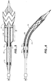
- Figure 6 shows a curved configuration of the stent graft delivery assembly of Figure 3. Is this Figure the anti kinking function of an anti kinking spacer 83 with tapered windings can clearly be seen.
- the wall of the containment sheath is maintained in a smooth non buckling (kinking) transition.
- Figure 8 provides a close up view of the usefulness of the tapered winding sections, where as the structure bends along the central axis the gaps between adjacent outer radial edges at the inside of the bend are diminished while the gaps between windings at the outer radial gap at the outside of the bend are increased.
- This configuration generally maintains the axial length of the spacer close to the central axis of the catheter, so that less gaps (sloppiness, spacing) are required between the anti kink spacer and its surround chamber, which reduces the likelihood that kinking will occur in these gaps.
- Figures 7 and 7A show a partial side view and a cross sectional view of a helical (Slinky® - like) anti kinking spacer as pictured in Figure 3.
- the stacked windings surrounding the catheter body must separate to create a pivot point (between each of two adjacent windings) at the inside of the bend in this curve configuration.
- the surrounding chamber sheath retraction portion of the containment sheath
- the surrounding chamber must always be sized long enough to accommodate the increased length of the outside diameter of the bend without binding at the ends and displacing and distorting the stent cup plungers 66, 67 or fixed seal mount 73.
- tapered winding configuration of the anti kinking member shown in Figure 8 requires a smaller increase in the outer circumferential length than for the configuration shown in Figure 7, as the pivot point for bends is located closer to the center of the catheter.
- Figure 9A and 9B show the partial cross section of two alternative constructions of a containment sheath according to an embodiment of the invention.
- a first material section 96 having friction reducing qualities (such as PEBAX) for the easy release of a spring loaded (self expanding) stent graft contained therein is fixed through a fused joint 95 to a second more rigid material section 98 whose material qualities are chosen to maintain rigidity (e.g., PE) and the sealing of the fluid receiving chamber 75.
- a first material section 97 has increased lubricity on its inner surface
- a second material section 99 has structural properties compatible with use as walls of pressurized chambers and for maintaining seal integrity.
- the change in diameters shown in Figure 9B is done through a transition section 101 with a joint 100 between the two material section, though the transition section could be a third material.
- the transition section could be a third material.
- a standard sized catheter could be used all the way to the location of the joint, before the transition to a larger size is attached, reducing the need for specialized structures.
- the thickness of the two section can be varied according the structural requirements, e.g., the stent containing portion 97 has a thinner wall than the second material retraction section 99.
- Figures 10A and 10B show side views of a portion of the distal section of the catheter body as shown in the previous Figures.
- Figure 10A pictures a configuration used in a uniform diameter configuration such as shown in Figure 9A.
- the catheter includes the distal nose 56, the compressed stent retention section 78, the stent cup plunger 66 engaged on it, the sheath retraction section 80, the fixed seal mount 73 (including a seal limit plate with two adjacent grooves for O-ring retention), and a fluid opening 76.
- the catheter configured for use with the dual diameter sheath configuration of Figure 9B includes the distal nose 57, the compressed stent retention section 79, the stent cup plunger 67 engaged on it, the sheath retraction section 81, the fixed seal mount 73 , and a fluid opening 76.
- Figure 11 as briefly discussed above, also show a guidewire lumen 90 and a fluid pressurizing lumen 92 in the catheter body.
- Figure 12 shows a cross section of the fluid pressurizing lumen 92 at the location of the fluid opening 76 which releases fluid into the fluid receiving chamber shown around the catheter 34.
- Figure 13 shows an alternate embodiment of a lumen arrangement in the catheter 34.
- a guidewire lumen 91 is centralized, within annular space acting as a fluid pressurizing lumen 93 to provide release of fluid into the fluid receiving chamber 75 through the fluid opening 77.
- An embodiment of the invention includes a method for hydraulically retracting a stent containment sheath comprising the steps of: providing a catheter having fixed seal fixed to a fixed seal mount thereon, with a fluid receiving chamber section on one side of the fixed seal and an anti kinking spacer on a second side of the with a plunger cup disposed at the end of the antikinking spacer opposite the fixed seal with a stent in a compressed pre deployment position disposed around the stent at a stent retention section of the catheter beyond the plunger cup; surrounding a portion of a distal end of the catheter with a containment sheath such sheath containing the fixed seal and the fixed seal mount and the antikinking spacer and the plunger cup and the stent in the pre deployment position, the containment sheath being sized to seal against the fixed seal of the catheter and including a movable seal which moves with the containment catheter and seals against the catheter to establish a fluid receiving chamber between the catheter, the containment sheath and the fixed seal and
Landscapes
- Health & Medical Sciences (AREA)
- Engineering & Computer Science (AREA)
- Biomedical Technology (AREA)
- Cardiology (AREA)
- Oral & Maxillofacial Surgery (AREA)
- Transplantation (AREA)
- Heart & Thoracic Surgery (AREA)
- Vascular Medicine (AREA)
- Life Sciences & Earth Sciences (AREA)
- Animal Behavior & Ethology (AREA)
- General Health & Medical Sciences (AREA)
- Public Health (AREA)
- Veterinary Medicine (AREA)
- Prostheses (AREA)
- Media Introduction/Drainage Providing Device (AREA)
Applications Claiming Priority (2)
| Application Number | Priority Date | Filing Date | Title |
|---|---|---|---|
| US24030800P | 2000-10-13 | 2000-10-13 | |
| US240308P | 2000-10-13 |
Publications (3)
| Publication Number | Publication Date |
|---|---|
| EP1208816A2 true EP1208816A2 (de) | 2002-05-29 |
| EP1208816A3 EP1208816A3 (de) | 2003-03-26 |
| EP1208816B1 EP1208816B1 (de) | 2005-12-14 |
Family
ID=22906031
Family Applications (1)
| Application Number | Title | Priority Date | Filing Date |
|---|---|---|---|
| EP01124605A Expired - Lifetime EP1208816B1 (de) | 2000-10-13 | 2001-10-15 | Hydraulisches Stenteinbringungssystem |
Country Status (3)
| Country | Link |
|---|---|
| US (1) | US7163552B2 (de) |
| EP (1) | EP1208816B1 (de) |
| DE (1) | DE60115821T2 (de) |
Cited By (25)
| Publication number | Priority date | Publication date | Assignee | Title |
|---|---|---|---|---|
| WO2003086236A3 (en) * | 2002-04-05 | 2004-03-25 | Scimed Life Systems Inc | Radial coil expandable medical wire |
| WO2005020856A3 (en) * | 2003-09-02 | 2005-04-21 | Abbott Lab | Delivery system for a medical device |
| DE10346200A1 (de) * | 2003-09-30 | 2005-05-04 | Jotec Gmbh | Einführsystem mit einem selbstexpandierenden Stent |
| EP1716822A1 (de) * | 2005-04-18 | 2006-11-02 | Medtronic Vascular, Inc. | Intravaskuläre Einführvorrichtung mit verbesserten Entfaltungsmöglichkeiten |
| WO2006124823A3 (en) * | 2005-05-13 | 2007-05-18 | Alveolus Inc | Intravascular implant delivery device with anchoring features and associated method |
| US7338501B2 (en) | 2002-01-16 | 2008-03-04 | Boston Scientific Scimed, Inc. | Treatment and removal of objects in anatomical lumens |
| WO2008066917A1 (en) | 2006-11-30 | 2008-06-05 | William Cook Europe Aps | Pusher sheath and deployment device |
| WO2008153765A3 (en) * | 2007-05-24 | 2009-02-05 | Cook Inc | Apparatus and methods for deploying self-expanding stents |
| US7780716B2 (en) | 2003-09-02 | 2010-08-24 | Abbott Laboratories | Delivery system for a medical device |
| US7794489B2 (en) | 2003-09-02 | 2010-09-14 | Abbott Laboratories | Delivery system for a medical device |
| US7799065B2 (en) | 2003-09-02 | 2010-09-21 | Abbott Laboratories | Delivery system for a medical device |
| DE102009019823A1 (de) | 2009-05-04 | 2010-11-11 | Acancis Gmbh & Co. Kg | Medizinischer Katheter, medizinisches System mit einem derartigen Katheter und Ladevorrichtung zur Herstellung eines derartigen Katheters |
| WO2011008538A1 (en) * | 2009-06-29 | 2011-01-20 | Med Institute, Inc. | Slotted pusher rod for flexible delivery system |
| RU2454974C2 (ru) * | 2006-10-22 | 2012-07-10 | Айдев Текнолоджиз, Инк. | Устройства и способы для продвижения стентов |
| CH707319A1 (de) * | 2012-12-11 | 2014-06-13 | Carag Ag | Stentapplikator. |
| CN104093381A (zh) * | 2012-05-09 | 2014-10-08 | 雅培心血管系统有限公司 | 具有带串联室的液压致动器的导管 |
| US9283101B2 (en) | 2013-03-12 | 2016-03-15 | Abbott Cardiovascular Systems Inc. | Catheter having hydraulic actuator and locking system |
| US9808363B2 (en) | 2014-09-10 | 2017-11-07 | The Cleveland Clinic Foundation | Frame structures, stent grafts incorporating the same, and methods for extended aortic repair |
| US9925074B2 (en) | 1999-02-01 | 2018-03-27 | Board Of Regents, The University Of Texas System | Plain woven stents |
| US10022255B2 (en) | 2016-04-11 | 2018-07-17 | Idev Technologies, Inc. | Stent delivery system having anisotropic sheath |
| US10039659B2 (en) | 2012-05-09 | 2018-08-07 | Abbott Cardiovascular Systems Inc. | Catheter having hydraulic actuator |
| US10420662B2 (en) | 2013-03-12 | 2019-09-24 | Abbott Cardiovascular Systems Inc. | Catheter having movable tubular structure and proximal stopper |
| US10531971B2 (en) | 2013-03-12 | 2020-01-14 | Abbott Cardiovascular System Inc. | Balloon catheter having hydraulic actuator |
| US10675164B2 (en) | 2012-05-09 | 2020-06-09 | Abbott Cardiovascular Systems Inc. | Catheter having dual balloon hydraulic actuator |
| US11076945B2 (en) | 2017-10-07 | 2021-08-03 | The Cleveland Clinic Foundation | Endovascular grafts and methods for extended aortic repair |
Families Citing this family (184)
| Publication number | Priority date | Publication date | Assignee | Title |
|---|---|---|---|---|
| WO2003003944A2 (en) | 2001-07-06 | 2003-01-16 | Angiomed Gmbh & Co. Medizintechnik Kg | Delivery system having a rapid pusher assembly for self-expanding stent, and stent exchange configuration |
| GB0123633D0 (en) | 2001-10-02 | 2001-11-21 | Angiomed Ag | Stent delivery system |
| US8721713B2 (en) * | 2002-04-23 | 2014-05-13 | Medtronic, Inc. | System for implanting a replacement valve |
| EP1388328A1 (de) * | 2002-08-07 | 2004-02-11 | Abbott Laboratories Vascular Enterprises Limited | Vorrichtung zum Ein- und Anbringen eines ausdehnbaren Stents in ein Blutgefäss |
| GB0327306D0 (en) * | 2003-11-24 | 2003-12-24 | Angiomed Gmbh & Co | Catheter device |
| US8568467B2 (en) | 2003-01-15 | 2013-10-29 | Angiomed Gmbh & Co. Medizintechnik Kg | Trans-luminal surgical device |
| GB0310714D0 (en) | 2003-05-09 | 2003-06-11 | Angiomed Ag | Fluid flow management in stent delivery system |
| US8500792B2 (en) | 2003-09-03 | 2013-08-06 | Bolton Medical, Inc. | Dual capture device for stent graft delivery system and method for capturing a stent graft |
| US7763063B2 (en) | 2003-09-03 | 2010-07-27 | Bolton Medical, Inc. | Self-aligning stent graft delivery system, kit, and method |
| US20080264102A1 (en) | 2004-02-23 | 2008-10-30 | Bolton Medical, Inc. | Sheath Capture Device for Stent Graft Delivery System and Method for Operating Same |
| US20070198078A1 (en) | 2003-09-03 | 2007-08-23 | Bolton Medical, Inc. | Delivery system and method for self-centering a Proximal end of a stent graft |
| US11596537B2 (en) | 2003-09-03 | 2023-03-07 | Bolton Medical, Inc. | Delivery system and method for self-centering a proximal end of a stent graft |
| US9198786B2 (en) | 2003-09-03 | 2015-12-01 | Bolton Medical, Inc. | Lumen repair device with capture structure |
| US8292943B2 (en) | 2003-09-03 | 2012-10-23 | Bolton Medical, Inc. | Stent graft with longitudinal support member |
| US11259945B2 (en) | 2003-09-03 | 2022-03-01 | Bolton Medical, Inc. | Dual capture device for stent graft delivery system and method for capturing a stent graft |
| US20050055080A1 (en) * | 2003-09-05 | 2005-03-10 | Naim Istephanous | Modulated stents and methods of making the stents |
| EP3308744B2 (de) | 2004-03-11 | 2023-08-02 | Percutaneous Cardiovascular Solutions Pty Limited | Perkutane herzklappenprothese |
| WO2005117758A1 (en) * | 2004-05-28 | 2005-12-15 | Cook Incorporated | Exchangeable delivery system for expandable prosthetic devices |
| JP2008513060A (ja) | 2004-09-14 | 2008-05-01 | エドワーズ ライフサイエンシーズ アーゲー | 心臓弁逆流の処置のためのデバイスおよび方法 |
| DE102005003632A1 (de) | 2005-01-20 | 2006-08-17 | Fraunhofer-Gesellschaft zur Förderung der angewandten Forschung e.V. | Katheter für die transvaskuläre Implantation von Herzklappenprothesen |
| DE102006039823A1 (de) * | 2005-02-25 | 2008-03-20 | Strecker, Ernst Peter, Prof. Dr. med. | Katheter-Stent-Vorrichtung |
| US7803180B2 (en) * | 2005-04-04 | 2010-09-28 | Flexible Stenting Solutions, Inc. | Flexible stent |
| WO2006113868A2 (en) * | 2005-04-20 | 2006-10-26 | Cook Incorporated | Medical delivery apparatus having tapered components |
| US9480589B2 (en) * | 2005-05-13 | 2016-11-01 | Boston Scientific Scimed, Inc. | Endoprosthesis delivery system |
| US20070043420A1 (en) * | 2005-08-17 | 2007-02-22 | Medtronic Vascular, Inc. | Apparatus and method for stent-graft release using a cap |
| US9084694B2 (en) * | 2005-09-09 | 2015-07-21 | Boston Scientific Scimed, Inc. | Coil shaft |
| US20070073377A1 (en) * | 2005-09-27 | 2007-03-29 | Mcdonald Michael B | Method for placing a stent through a constricted lumen, and medical device |
| US7780714B2 (en) * | 2005-11-01 | 2010-08-24 | Cordis Corporation | Implant delivery apparatus |
| AU2006315812B2 (en) | 2005-11-10 | 2013-03-28 | Cardiaq Valve Technologies, Inc. | Balloon-expandable, self-expanding, vascular prosthesis connecting stent |
| AU2006330816B2 (en) * | 2005-12-23 | 2012-05-24 | Cook Medical Technologies Llc | Prosthesis deployment system |
| US11026822B2 (en) | 2006-01-13 | 2021-06-08 | C. R. Bard, Inc. | Stent delivery system |
| JP5345856B2 (ja) | 2006-01-13 | 2013-11-20 | シー・アール・バード・インコーポレーテッド | ステント搬送システム |
| US8518098B2 (en) | 2006-02-21 | 2013-08-27 | Cook Medical Technologies Llc | Split sheath deployment system |
| US20070208407A1 (en) * | 2006-03-06 | 2007-09-06 | Michael Gerdts | Medical device delivery systems |
| US20080114435A1 (en) * | 2006-03-07 | 2008-05-15 | Med Institute, Inc. | Flexible delivery system |
| US8118853B2 (en) * | 2006-06-19 | 2012-02-21 | Cook Medical Technologies Llc | Prosthesis delivery and deployment device |
| GB0615658D0 (en) | 2006-08-07 | 2006-09-13 | Angiomed Ag | Hand-held actuator device |
| MX344492B (es) | 2006-10-22 | 2016-12-16 | Idev Tech Inc * | Dispositivos y métodos para el avance de stent. |
| US8070799B2 (en) | 2006-12-19 | 2011-12-06 | Sorin Biomedica Cardio S.R.L. | Instrument and method for in situ deployment of cardiac valve prostheses |
| US7643886B2 (en) * | 2007-01-25 | 2010-01-05 | Cardiac Pacemakers, Inc. | Hydraulic actuation of lead fixation member |
| US7896915B2 (en) | 2007-04-13 | 2011-03-01 | Jenavalve Technology, Inc. | Medical device for treating a heart valve insufficiency |
| GB0713497D0 (en) | 2007-07-11 | 2007-08-22 | Angiomed Ag | Device for catheter sheath retraction |
| US9119742B2 (en) * | 2007-07-16 | 2015-09-01 | Cook Medical Technologies Llc | Prosthesis delivery and deployment device |
| US7988723B2 (en) | 2007-08-02 | 2011-08-02 | Flexible Stenting Solutions, Inc. | Flexible stent |
| US20090099638A1 (en) * | 2007-10-11 | 2009-04-16 | Med Institute, Inc. | Motorized deployment system |
| US8114144B2 (en) | 2007-10-17 | 2012-02-14 | Abbott Cardiovascular Systems Inc. | Rapid-exchange retractable sheath self-expanding delivery system with incompressible inner member and flexible distal assembly |
| US10022250B2 (en) | 2007-12-12 | 2018-07-17 | Intact Vascular, Inc. | Deployment device for placement of multiple intraluminal surgical staples |
| US8128677B2 (en) | 2007-12-12 | 2012-03-06 | Intact Vascular LLC | Device and method for tacking plaque to a blood vessel wall |
| US9603730B2 (en) | 2007-12-12 | 2017-03-28 | Intact Vascular, Inc. | Endoluminal device and method |
| US9375327B2 (en) | 2007-12-12 | 2016-06-28 | Intact Vascular, Inc. | Endovascular implant |
| US10166127B2 (en) | 2007-12-12 | 2019-01-01 | Intact Vascular, Inc. | Endoluminal device and method |
| US7896911B2 (en) | 2007-12-12 | 2011-03-01 | Innovasc Llc | Device and method for tacking plaque to blood vessel wall |
| US9044318B2 (en) | 2008-02-26 | 2015-06-02 | Jenavalve Technology Gmbh | Stent for the positioning and anchoring of a valvular prosthesis |
| WO2011104269A1 (en) | 2008-02-26 | 2011-09-01 | Jenavalve Technology Inc. | Stent for the positioning and anchoring of a valvular prosthesis in an implantation site in the heart of a patient |
| US20090276040A1 (en) | 2008-05-01 | 2009-11-05 | Edwards Lifesciences Corporation | Device and method for replacing mitral valve |
| US8992591B2 (en) * | 2008-05-07 | 2015-03-31 | Cook Medical Technologies Llc | Delivery system with low longitudinal compressibility |
| GB0810749D0 (en) | 2008-06-11 | 2008-07-16 | Angiomed Ag | Catherter delivery device |
| US9750625B2 (en) | 2008-06-11 | 2017-09-05 | C.R. Bard, Inc. | Catheter delivery device |
| JP5484458B2 (ja) | 2008-06-30 | 2014-05-07 | ボルトン メディカル インコーポレイテッド | 腹部大動脈瘤システム |
| US8313493B2 (en) * | 2008-07-10 | 2012-11-20 | Cook Medical Technologies Llc | Hydraulic guidewire advancement system |
| AU2009295960A1 (en) | 2008-09-29 | 2010-04-01 | Cardiaq Valve Technologies, Inc. | Heart valve |
| WO2010038634A1 (ja) * | 2008-09-30 | 2010-04-08 | テルモ株式会社 | ステントデリバリーシステム |
| EP2341871B1 (de) * | 2008-10-01 | 2017-03-22 | Edwards Lifesciences CardiAQ LLC | Abgabesystem für ein gefässimplantat |
| US9149376B2 (en) | 2008-10-06 | 2015-10-06 | Cordis Corporation | Reconstrainable stent delivery system |
| WO2010057262A1 (en) | 2008-11-21 | 2010-05-27 | Percutaneous Cardiovascular Solutions Pty Limited | Heart valve prosthesis and method |
| CH700476A1 (de) * | 2009-02-23 | 2010-08-31 | Carag Ag | Zuführsystem. |
| US9301863B2 (en) * | 2009-03-10 | 2016-04-05 | Medtronic Vascular, Inc. | Prosthesis delivery apparatus and methods |
| AU2010223953B2 (en) | 2009-03-13 | 2014-05-01 | Bolton Medical, Inc. | System and method for deploying an endoluminal prosthesis at a surgical site |
| EP4119098A1 (de) | 2009-04-15 | 2023-01-18 | Edwards Lifesciences CardiAQ LLC | Gefässimplantat und freisetzungssystem |
| CA2760461C (en) | 2009-04-29 | 2014-10-07 | The Cleveland Clinic Foundation | Apparatus and method for replacing a diseased cardiac valve |
| US9168105B2 (en) | 2009-05-13 | 2015-10-27 | Sorin Group Italia S.R.L. | Device for surgical interventions |
| US9730790B2 (en) | 2009-09-29 | 2017-08-15 | Edwards Lifesciences Cardiaq Llc | Replacement valve and method |
| US8449599B2 (en) | 2009-12-04 | 2013-05-28 | Edwards Lifesciences Corporation | Prosthetic valve for replacing mitral valve |
| EP2497448A4 (de) * | 2009-12-28 | 2013-06-05 | Terumo Corp | Stentträgersystem |
| US8579964B2 (en) | 2010-05-05 | 2013-11-12 | Neovasc Inc. | Transcatheter mitral valve prosthesis |
| US10856978B2 (en) | 2010-05-20 | 2020-12-08 | Jenavalve Technology, Inc. | Catheter system |
| ES2441043T3 (es) * | 2010-05-20 | 2014-01-31 | Jenavalve Technology Inc. | Sistema de catéter para introducir un stent de válvula cardíaca expansible en el cuerpo de un paciente |
| US11278406B2 (en) | 2010-05-20 | 2022-03-22 | Jenavalve Technology, Inc. | Catheter system for introducing an expandable heart valve stent into the body of a patient, insertion system with a catheter system and medical device for treatment of a heart valve defect |
| WO2011147849A1 (en) | 2010-05-25 | 2011-12-01 | Jenavalve Technology Inc. | Prosthetic heart valve and transcatheter delivered endoprosthesis comprising a prosthetic heart valve and a stent |
| US9023095B2 (en) | 2010-05-27 | 2015-05-05 | Idev Technologies, Inc. | Stent delivery system with pusher assembly |
| AU2011271007A1 (en) | 2010-06-21 | 2013-01-31 | Cardiaq Valve Technologies, Inc. | Replacement heart valve |
| CN103025277B (zh) | 2010-07-21 | 2015-05-20 | 库克医学技术有限责任公司 | 用于支架递送系统的控制系统 |
| WO2012040655A2 (en) | 2010-09-23 | 2012-03-29 | Cardiaq Valve Technologies, Inc. | Replacement heart valves, delivery devices and methods |
| JP5697138B2 (ja) * | 2010-09-27 | 2015-04-08 | 株式会社カネカ | ステント搬送用カテーテルシステム |
| GB201017834D0 (en) | 2010-10-21 | 2010-12-01 | Angiomed Ag | System to deliver a bodily implant |
| CN103228234B (zh) * | 2011-02-24 | 2016-05-04 | 泰尔茂株式会社 | 支架输送系统 |
| US9554897B2 (en) | 2011-04-28 | 2017-01-31 | Neovasc Tiara Inc. | Methods and apparatus for engaging a valve prosthesis with tissue |
| US9308087B2 (en) | 2011-04-28 | 2016-04-12 | Neovasc Tiara Inc. | Sequentially deployed transcatheter mitral valve prosthesis |
| US12502276B2 (en) | 2011-05-16 | 2025-12-23 | Edwards Lifesciences Corporation | Inversion delivery device and method for a prosthesis |
| US20120303048A1 (en) | 2011-05-24 | 2012-11-29 | Sorin Biomedica Cardio S.R.I. | Transapical valve replacement |
| US10271973B2 (en) | 2011-06-03 | 2019-04-30 | Intact Vascular, Inc. | Endovascular implant |
| CN104159543B (zh) | 2011-10-21 | 2016-10-12 | 耶拿阀门科技公司 | 用于将可扩张心脏瓣膜支架引入患者体内的导管系统 |
| WO2013112768A1 (en) | 2012-01-25 | 2013-08-01 | Intact Vascular, Inc. | Endoluminal device and method |
| US9579198B2 (en) * | 2012-03-01 | 2017-02-28 | Twelve, Inc. | Hydraulic delivery systems for prosthetic heart valve devices and associated methods |
| BR112014025430A2 (pt) | 2012-04-12 | 2020-03-10 | Bolton Medical, Inc. | Dispositivo de envio protético vascular e método de uso |
| JP6227632B2 (ja) | 2012-05-16 | 2017-11-08 | イェーナヴァルヴ テクノロジー ゲゼルシャフト ミット ベシュレンクテル ハフツング | 拡張可能心臓代用弁を導入するためのカテーテル送達システムおよび心臓弁欠陥の治療のための医療デバイス |
| US9345573B2 (en) | 2012-05-30 | 2016-05-24 | Neovasc Tiara Inc. | Methods and apparatus for loading a prosthesis onto a delivery system |
| US9901471B2 (en) * | 2013-01-30 | 2018-02-27 | Cook Medical Technologies Llc | Spring assisted medical device deployment assembly |
| US9439763B2 (en) | 2013-02-04 | 2016-09-13 | Edwards Lifesciences Corporation | Prosthetic valve for replacing mitral valve |
| EP2774586B1 (de) * | 2013-03-06 | 2016-11-23 | Cook Medical Technologies LLC | EINFÜHRERHÜLSE MIT UNGLEICHMÄßIGER INNENFLÄCHE |
| US10583002B2 (en) | 2013-03-11 | 2020-03-10 | Neovasc Tiara Inc. | Prosthetic valve with anti-pivoting mechanism |
| CN105228562B (zh) * | 2013-03-12 | 2017-12-22 | 雅培心血管系统有限公司 | 具有液压致动器和锁定系统的导管 |
| EP2967950A1 (de) * | 2013-03-12 | 2016-01-20 | Abbott Cardiovascular Systems Inc. | Katheter mit beweglicher rohrförmiger struktur und proximalem stopfen |
| US9326875B2 (en) | 2013-03-13 | 2016-05-03 | Abbott Cardiovascular Systems Inc. | Catheter having a movable tubular structure and method of making |
| EP2967948A1 (de) * | 2013-03-13 | 2016-01-20 | Abbott Cardiovascular Systems Inc. | Katheter mit beweglicher rohrförmiger struktur |
| US9681951B2 (en) | 2013-03-14 | 2017-06-20 | Edwards Lifesciences Cardiaq Llc | Prosthesis with outer skirt and anchors |
| US20140277427A1 (en) | 2013-03-14 | 2014-09-18 | Cardiaq Valve Technologies, Inc. | Prosthesis for atraumatically grasping intralumenal tissue and methods of delivery |
| US9730791B2 (en) | 2013-03-14 | 2017-08-15 | Edwards Lifesciences Cardiaq Llc | Prosthesis for atraumatically grasping intralumenal tissue and methods of delivery |
| US9439751B2 (en) | 2013-03-15 | 2016-09-13 | Bolton Medical, Inc. | Hemostasis valve and delivery systems |
| US9572665B2 (en) | 2013-04-04 | 2017-02-21 | Neovasc Tiara Inc. | Methods and apparatus for delivering a prosthetic valve to a beating heart |
| JP5904557B2 (ja) * | 2013-04-30 | 2016-04-13 | 朝日インテック株式会社 | プッシャーガイドワイヤ |
| DE102013104565B3 (de) * | 2013-05-03 | 2014-10-16 | Jotec Gmbh | Pusher-Baugruppe für ein Einführsystem für ein selbstexpandierendes Gefäßimplantat sowie ein entsprechendes Einführsystem |
| WO2015013666A1 (en) | 2013-07-26 | 2015-01-29 | Cardiaq Valve Technologies, Inc. | Systems and methods for sealing openings in an anatomical wall |
| EP2839815A1 (de) * | 2013-08-20 | 2015-02-25 | Biotronik AG | Kathetersystem mit beweglicher Hülle |
| WO2015028209A1 (en) | 2013-08-30 | 2015-03-05 | Jenavalve Technology Gmbh | Radially collapsible frame for a prosthetic valve and method for manufacturing such a frame |
| US10531953B2 (en) | 2013-10-28 | 2020-01-14 | Symetis Sa | Stent-valve, delivery apparatus and method of use |
| DE102013224298A1 (de) * | 2013-11-27 | 2015-05-28 | Deutsches Herzzentrum Berlin | Vorrichtung zum Implantieren eines selbstexpandierbaren Stents in ein Hohlorgan |
| KR101514055B1 (ko) * | 2013-12-17 | 2015-04-21 | 주식회사 스텐다드싸이텍 | 스텐트 삽입장치 |
| WO2015127283A1 (en) | 2014-02-21 | 2015-08-27 | Cardiaq Valve Technologies, Inc. | Delivery device for controlled deployement of a replacement valve |
| USD755384S1 (en) | 2014-03-05 | 2016-05-03 | Edwards Lifesciences Cardiaq Llc | Stent |
| CN106456328A (zh) | 2014-05-19 | 2017-02-22 | 爱德华兹生命科学卡迪尔克有限责任公司 | 带有环形活瓣的二尖瓣膜替代品 |
| US9532870B2 (en) | 2014-06-06 | 2017-01-03 | Edwards Lifesciences Corporation | Prosthetic valve for replacing a mitral valve |
| BR112017006248A2 (pt) | 2014-09-28 | 2017-12-12 | Cardiokinetix Inc | aparelhos para o tratamento de insuficiência cardíaca |
| US10531951B2 (en) | 2014-11-26 | 2020-01-14 | Edwards Lifesciences Corporation | Transcatheter prosthetic heart valve and delivery system |
| US9375336B1 (en) | 2015-01-29 | 2016-06-28 | Intact Vascular, Inc. | Delivery device and method of delivery |
| US9433520B2 (en) | 2015-01-29 | 2016-09-06 | Intact Vascular, Inc. | Delivery device and method of delivery |
| AU2015201411B1 (en) | 2015-03-18 | 2015-09-24 | Cook Medical Technologies Llc | An endograft introducer assembly having a transfer sheath |
| WO2016153918A1 (en) | 2015-03-20 | 2016-09-29 | Cardiokinetix, Inc. | Systems and methods for delivering an implantable device |
| EP3270825B1 (de) | 2015-03-20 | 2020-04-22 | JenaValve Technology, Inc. | Herzklappenprothesenzuführsystem |
| JP6976512B2 (ja) | 2015-03-27 | 2021-12-08 | プロジェクト モレー, インコーポレイテッド | カテーテルおよびその他の使用のための関節運動システム、デバイス、および方法 |
| US10441416B2 (en) | 2015-04-21 | 2019-10-15 | Edwards Lifesciences Corporation | Percutaneous mitral valve replacement device |
| US10376363B2 (en) | 2015-04-30 | 2019-08-13 | Edwards Lifesciences Cardiaq Llc | Replacement mitral valve, delivery system for replacement mitral valve and methods of use |
| EP3288495B1 (de) | 2015-05-01 | 2019-09-25 | JenaValve Technology, Inc. | Vorrichtung mit reduzierter herzschrittmacherrate bei herzklappenersatz |
| US10226335B2 (en) | 2015-06-22 | 2019-03-12 | Edwards Lifesciences Cardiaq Llc | Actively controllable heart valve implant and method of controlling same |
| US10092400B2 (en) | 2015-06-23 | 2018-10-09 | Edwards Lifesciences Cardiaq Llc | Systems and methods for anchoring and sealing a prosthetic heart valve |
| US10575951B2 (en) | 2015-08-26 | 2020-03-03 | Edwards Lifesciences Cardiaq Llc | Delivery device and methods of use for transapical delivery of replacement mitral valve |
| US10117744B2 (en) | 2015-08-26 | 2018-11-06 | Edwards Lifesciences Cardiaq Llc | Replacement heart valves and methods of delivery |
| US10350066B2 (en) | 2015-08-28 | 2019-07-16 | Edwards Lifesciences Cardiaq Llc | Steerable delivery system for replacement mitral valve and methods of use |
| CN108601925B (zh) | 2015-12-04 | 2021-06-29 | 项目莫里股份有限公司 | 用于导管和其他用途的输入和铰接系统 |
| WO2017096362A1 (en) | 2015-12-04 | 2017-06-08 | Barrish Mark D | Lateral articulation anchors for catheters and other uses |
| US10993824B2 (en) | 2016-01-01 | 2021-05-04 | Intact Vascular, Inc. | Delivery device and method of delivery |
| WO2017143170A1 (en) | 2016-02-17 | 2017-08-24 | Keith Phillip Laby | Local contraction of flexible bodies using balloon expansion for extension-contraction catheter articulation and other uses |
| WO2017165810A1 (en) * | 2016-03-25 | 2017-09-28 | Phillip Laby | Fluid-actuated sheath displacement and articulation behavior improving systems, devices, and methods for catheters, continuum manipulators, and other uses |
| US11420021B2 (en) | 2016-03-25 | 2022-08-23 | Project Moray, Inc. | Fluid-actuated displacement for catheters, continuum manipulators, and other uses |
| USD815744S1 (en) | 2016-04-28 | 2018-04-17 | Edwards Lifesciences Cardiaq Llc | Valve frame for a delivery system |
| WO2017195125A1 (en) | 2016-05-13 | 2017-11-16 | Jenavalve Technology, Inc. | Heart valve prosthesis delivery system and method for delivery of heart valve prosthesis with introducer sheath and loading system |
| US10350062B2 (en) | 2016-07-21 | 2019-07-16 | Edwards Lifesciences Corporation | Replacement heart valve prosthesis |
| US10646340B2 (en) | 2016-08-19 | 2020-05-12 | Edwards Lifesciences Corporation | Steerable delivery system for replacement mitral valve |
| US10639143B2 (en) | 2016-08-26 | 2020-05-05 | Edwards Lifesciences Corporation | Multi-portion replacement heart valve prosthesis |
| WO2018050262A1 (en) * | 2016-09-19 | 2018-03-22 | Cti Vascular Ag | Catheter system for treating vascular and non-vascular diseases |
| WO2018064398A1 (en) | 2016-09-28 | 2018-04-05 | Project Moray, Inc. | Arrhythmia diagnostic and/or therapy delivery methods and devices, and robotic systems for other uses |
| US10814102B2 (en) | 2016-09-28 | 2020-10-27 | Project Moray, Inc. | Base station, charging station, and/or server for robotic catheter systems and other uses, and improved articulated devices and systems |
| US10758348B2 (en) | 2016-11-02 | 2020-09-01 | Edwards Lifesciences Corporation | Supra and sub-annular mitral valve delivery system |
| US10835401B2 (en) * | 2016-12-29 | 2020-11-17 | Boston Scientific Scimed, Inc. | Hydration delivery system for stents |
| US10376396B2 (en) | 2017-01-19 | 2019-08-13 | Covidien Lp | Coupling units for medical device delivery systems |
| CN106580531B (zh) * | 2017-01-24 | 2018-03-23 | 南华大学 | 用于可膨胀支架的递送系统 |
| US11197754B2 (en) | 2017-01-27 | 2021-12-14 | Jenavalve Technology, Inc. | Heart valve mimicry |
| CN110381896B (zh) * | 2017-03-31 | 2022-09-13 | 日本瑞翁株式会社 | 支架传递装置 |
| US10575950B2 (en) | 2017-04-18 | 2020-03-03 | Twelve, Inc. | Hydraulic systems for delivering prosthetic heart valve devices and associated methods |
| US10905861B2 (en) | 2017-04-25 | 2021-02-02 | Project Moray, Inc. | Matrix supported balloon articulation systems, devices, and methods for catheters and other uses |
| US10646338B2 (en) | 2017-06-02 | 2020-05-12 | Twelve, Inc. | Delivery systems with telescoping capsules for deploying prosthetic heart valve devices and associated methods |
| EP3648708A4 (de) | 2017-07-06 | 2021-03-31 | Edwards Lifesciences Corporation | Steuerbares abgabesystem und komponenten |
| US11660218B2 (en) | 2017-07-26 | 2023-05-30 | Intact Vascular, Inc. | Delivery device and method of delivery |
| EP3720390B1 (de) | 2018-01-25 | 2024-05-01 | Edwards Lifesciences Corporation | Einführsystem zur unterstützten rückgewinnung oder neupositionierung eines klappenersatzes nach dem einsetzen |
| US11051934B2 (en) | 2018-02-28 | 2021-07-06 | Edwards Lifesciences Corporation | Prosthetic mitral valve with improved anchors and seal |
| CN112004504B (zh) * | 2018-04-12 | 2025-02-11 | 柯惠有限合伙公司 | 支架递送系统和医疗装置递送系统 |
| US11123209B2 (en) | 2018-04-12 | 2021-09-21 | Covidien Lp | Medical device delivery |
| US11413176B2 (en) | 2018-04-12 | 2022-08-16 | Covidien Lp | Medical device delivery |
| US11071637B2 (en) | 2018-04-12 | 2021-07-27 | Covidien Lp | Medical device delivery |
| US10786377B2 (en) | 2018-04-12 | 2020-09-29 | Covidien Lp | Medical device delivery |
| US11504231B2 (en) | 2018-05-23 | 2022-11-22 | Corcym S.R.L. | Cardiac valve prosthesis |
| WO2019224581A1 (en) | 2018-05-23 | 2019-11-28 | Sorin Group Italia S.R.L. | A device for the in-situ delivery of heart valve prostheses |
| EP3921012A1 (de) | 2019-02-04 | 2021-12-15 | Edwards Lifesciences Corporation | Führungsdrahtvorrichtungen und verfahren |
| EP3952790A1 (de) | 2019-04-12 | 2022-02-16 | W.L. Gore & Associates, Inc. | Ventil mit mehrteiligem rahmen und zugehörigen elastischen überbrückungsmerkmalen |
| ES2982566T3 (es) | 2019-04-23 | 2024-10-16 | Edwards Lifesciences Corp | Sistema de suministro de implantes motorizado |
| US11413174B2 (en) | 2019-06-26 | 2022-08-16 | Covidien Lp | Core assembly for medical device delivery systems |
| EP4171449B1 (de) | 2020-06-24 | 2026-03-04 | Bolton Medical, Inc. | Anti-backspin-komponente für eine vorrichtung zur freisetzung einer gefässprothese |
| WO2022132569A1 (en) | 2020-12-18 | 2022-06-23 | Edwards Lifesciences Corporation | Storage jar assembly for aprosthetic heart valve |
| US12458518B2 (en) | 2021-02-17 | 2025-11-04 | Covidien Lp | Medical device delivery devices, systems, and methods |
| US12109137B2 (en) | 2021-07-30 | 2024-10-08 | Covidien Lp | Medical device delivery |
| US11944558B2 (en) | 2021-08-05 | 2024-04-02 | Covidien Lp | Medical device delivery devices, systems, and methods |
| KR102918984B1 (ko) | 2021-10-27 | 2026-01-28 | 에드워즈 라이프사이언시스 코포레이션 | 인공 심장 판막의 클림핑 및 로딩을 위한 시스템 및 방법 |
| US12521531B2 (en) | 2022-10-12 | 2026-01-13 | Medtronic, Inc. | Interventional medical device with balloon-actuated cover |
| US12171658B2 (en) | 2022-11-09 | 2024-12-24 | Jenavalve Technology, Inc. | Catheter system for sequential deployment of an expandable implant |
Citations (2)
| Publication number | Priority date | Publication date | Assignee | Title |
|---|---|---|---|---|
| US5817101A (en) | 1997-03-13 | 1998-10-06 | Schneider (Usa) Inc | Fluid actuated stent delivery system |
| US6113608A (en) | 1998-11-20 | 2000-09-05 | Scimed Life Systems, Inc. | Stent delivery device |
Family Cites Families (18)
| Publication number | Priority date | Publication date | Assignee | Title |
|---|---|---|---|---|
| US5240537A (en) * | 1991-07-01 | 1993-08-31 | Namic U.S.A. Corporation | Method for manufacturing a soft tip catheter |
| DE59200548D1 (de) * | 1992-12-16 | 1994-10-27 | Schneider Europ Ag | Vorrichtung zum Implantieren einer selbstexpandierenden Endoprothese. |
| US5326011A (en) * | 1993-01-22 | 1994-07-05 | Printware, Inc. | Reduced-skew web drive between rollers of differing coefficients of friction, particularly to transport paper, metal or film in a laser imager |
| US5445646A (en) | 1993-10-22 | 1995-08-29 | Scimed Lifesystems, Inc. | Single layer hydraulic sheath stent delivery apparatus and method |
| US5571135A (en) | 1993-10-22 | 1996-11-05 | Scimed Life Systems Inc. | Stent delivery apparatus and method |
| IT1268777B1 (it) | 1994-10-05 | 1997-03-06 | Fogazzi Di Venturelli Andrea & | Introduttore di stent ad azione idraulica |
| ES2131253T3 (es) * | 1995-11-14 | 1999-07-16 | Schneider Europ Gmbh | Dispositivo para la implantacion de una endoprotesis. |
| US6254628B1 (en) | 1996-12-09 | 2001-07-03 | Micro Therapeutics, Inc. | Intracranial stent |
| US5772669A (en) | 1996-09-27 | 1998-06-30 | Scimed Life Systems, Inc. | Stent deployment catheter with retractable sheath |
| US5924664A (en) * | 1997-03-12 | 1999-07-20 | Ergo View Technologies Corp. | Keyboard support mechanism |
| US6004328A (en) | 1997-06-19 | 1999-12-21 | Solar; Ronald J. | Radially expandable intraluminal stent and delivery catheter therefore and method of using the same |
| US6206888B1 (en) | 1997-10-01 | 2001-03-27 | Scimed Life Systems, Inc. | Stent delivery system using shape memory retraction |
| US6019778A (en) | 1998-03-13 | 2000-02-01 | Cordis Corporation | Delivery apparatus for a self-expanding stent |
| WO2000018330A1 (en) * | 1998-09-30 | 2000-04-06 | Impra, Inc. | Delivery mechanism for implantable stent |
| US6254612B1 (en) | 1998-10-22 | 2001-07-03 | Cordis Neurovascular, Inc. | Hydraulic stent deployment system |
| US6726712B1 (en) * | 1999-05-14 | 2004-04-27 | Boston Scientific Scimed | Prosthesis deployment device with translucent distal end |
| US6368344B1 (en) * | 1999-12-16 | 2002-04-09 | Advanced Cardiovascular Systems, Inc. | Stent deployment system with reinforced inner member |
| US6942688B2 (en) * | 2000-02-29 | 2005-09-13 | Cordis Corporation | Stent delivery system having delivery catheter member with a clear transition zone |
-
2001
- 2001-10-15 US US09/978,243 patent/US7163552B2/en not_active Expired - Fee Related
- 2001-10-15 DE DE60115821T patent/DE60115821T2/de not_active Expired - Fee Related
- 2001-10-15 EP EP01124605A patent/EP1208816B1/de not_active Expired - Lifetime
Patent Citations (3)
| Publication number | Priority date | Publication date | Assignee | Title |
|---|---|---|---|---|
| US5817101A (en) | 1997-03-13 | 1998-10-06 | Schneider (Usa) Inc | Fluid actuated stent delivery system |
| US6056759A (en) | 1997-03-13 | 2000-05-02 | Schneider (Usa) Inc. | Fluid actuated stent delivery system |
| US6113608A (en) | 1998-11-20 | 2000-09-05 | Scimed Life Systems, Inc. | Stent delivery device |
Cited By (43)
| Publication number | Priority date | Publication date | Assignee | Title |
|---|---|---|---|---|
| US9925074B2 (en) | 1999-02-01 | 2018-03-27 | Board Of Regents, The University Of Texas System | Plain woven stents |
| US7338501B2 (en) | 2002-01-16 | 2008-03-04 | Boston Scientific Scimed, Inc. | Treatment and removal of objects in anatomical lumens |
| US8540729B2 (en) | 2002-01-16 | 2013-09-24 | Boston Scientific Scimed, Inc. | Treatment and removal of objects in anatomical lumens |
| US8382771B2 (en) | 2002-04-05 | 2013-02-26 | Boston Scientific Scimed, Inc. | Radial coil expandable medical wire |
| WO2003086236A3 (en) * | 2002-04-05 | 2004-03-25 | Scimed Life Systems Inc | Radial coil expandable medical wire |
| US7780716B2 (en) | 2003-09-02 | 2010-08-24 | Abbott Laboratories | Delivery system for a medical device |
| JP2007503916A (ja) * | 2003-09-02 | 2007-03-01 | アボット・ラボラトリーズ | 医療器具の送出システム |
| US7794489B2 (en) | 2003-09-02 | 2010-09-14 | Abbott Laboratories | Delivery system for a medical device |
| US7799065B2 (en) | 2003-09-02 | 2010-09-21 | Abbott Laboratories | Delivery system for a medical device |
| WO2005020856A3 (en) * | 2003-09-02 | 2005-04-21 | Abbott Lab | Delivery system for a medical device |
| AU2004268620B2 (en) * | 2003-09-02 | 2010-12-02 | Abbott Laboratories | Delivery system for a medical device |
| US10667933B2 (en) | 2003-09-30 | 2020-06-02 | Jotec Gmbh | Delivery system comprising a self expanding stent |
| DE10346200A1 (de) * | 2003-09-30 | 2005-05-04 | Jotec Gmbh | Einführsystem mit einem selbstexpandierenden Stent |
| EP1716822A1 (de) * | 2005-04-18 | 2006-11-02 | Medtronic Vascular, Inc. | Intravaskuläre Einführvorrichtung mit verbesserten Entfaltungsmöglichkeiten |
| US7828832B2 (en) | 2005-04-18 | 2010-11-09 | Medtronic Vascular, Inc. | Intravascular deployment device with improved deployment capability |
| WO2006124823A3 (en) * | 2005-05-13 | 2007-05-18 | Alveolus Inc | Intravascular implant delivery device with anchoring features and associated method |
| US7935140B2 (en) | 2005-05-13 | 2011-05-03 | Merit Medical Systems, Inc. | Delivery device with anchoring features and associated method |
| RU2454974C2 (ru) * | 2006-10-22 | 2012-07-10 | Айдев Текнолоджиз, Инк. | Устройства и способы для продвижения стентов |
| US9629736B2 (en) | 2006-10-22 | 2017-04-25 | Idev Technologies, Inc. | Secured strand end devices |
| US10470902B2 (en) | 2006-10-22 | 2019-11-12 | Idev Technologies, Inc. | Secured strand end devices |
| US9895242B2 (en) | 2006-10-22 | 2018-02-20 | Idev Technologies, Inc. | Secured strand end devices |
| WO2008066917A1 (en) | 2006-11-30 | 2008-06-05 | William Cook Europe Aps | Pusher sheath and deployment device |
| WO2008153765A3 (en) * | 2007-05-24 | 2009-02-05 | Cook Inc | Apparatus and methods for deploying self-expanding stents |
| DE102009019823A1 (de) | 2009-05-04 | 2010-11-11 | Acancis Gmbh & Co. Kg | Medizinischer Katheter, medizinisches System mit einem derartigen Katheter und Ladevorrichtung zur Herstellung eines derartigen Katheters |
| US9095464B2 (en) | 2009-06-29 | 2015-08-04 | Cook Medical Technologies Llc | Slotted pusher rod for flexible delivery system |
| WO2011008538A1 (en) * | 2009-06-29 | 2011-01-20 | Med Institute, Inc. | Slotted pusher rod for flexible delivery system |
| CN104093381A (zh) * | 2012-05-09 | 2014-10-08 | 雅培心血管系统有限公司 | 具有带串联室的液压致动器的导管 |
| US9271855B2 (en) | 2012-05-09 | 2016-03-01 | Abbott Cardiovascular Systems Inc. | Catheter having hydraulic actuator with tandem chambers |
| US10675164B2 (en) | 2012-05-09 | 2020-06-09 | Abbott Cardiovascular Systems Inc. | Catheter having dual balloon hydraulic actuator |
| CN104093381B (zh) * | 2012-05-09 | 2016-11-09 | 雅培心血管系统有限公司 | 具有带串联室的液压致动器的导管 |
| US10039659B2 (en) | 2012-05-09 | 2018-08-07 | Abbott Cardiovascular Systems Inc. | Catheter having hydraulic actuator |
| CH707319A1 (de) * | 2012-12-11 | 2014-06-13 | Carag Ag | Stentapplikator. |
| US9925077B2 (en) | 2012-12-11 | 2018-03-27 | Carag Ag | Stent applicator |
| WO2014089715A1 (de) | 2012-12-11 | 2014-06-19 | Carag Ag | Stentapplikator |
| US10327932B2 (en) | 2013-03-12 | 2019-06-25 | Abbott Cardiovascular Systems Inc. | Catheter having hydraulic actuator and locking system |
| US10420662B2 (en) | 2013-03-12 | 2019-09-24 | Abbott Cardiovascular Systems Inc. | Catheter having movable tubular structure and proximal stopper |
| US10531971B2 (en) | 2013-03-12 | 2020-01-14 | Abbott Cardiovascular System Inc. | Balloon catheter having hydraulic actuator |
| US9283101B2 (en) | 2013-03-12 | 2016-03-15 | Abbott Cardiovascular Systems Inc. | Catheter having hydraulic actuator and locking system |
| US10299946B2 (en) | 2014-09-10 | 2019-05-28 | The Cleveland Clinic Foundation | Frame structures, stent grafts incorporating the same, and methods for extended aortic repair |
| US9808363B2 (en) | 2014-09-10 | 2017-11-07 | The Cleveland Clinic Foundation | Frame structures, stent grafts incorporating the same, and methods for extended aortic repair |
| US10022255B2 (en) | 2016-04-11 | 2018-07-17 | Idev Technologies, Inc. | Stent delivery system having anisotropic sheath |
| US11076945B2 (en) | 2017-10-07 | 2021-08-03 | The Cleveland Clinic Foundation | Endovascular grafts and methods for extended aortic repair |
| US12521224B2 (en) | 2017-10-07 | 2026-01-13 | The Cleveland Clinic Foundation | Endovascular grafts and methods for extended aortic repair |
Also Published As
| Publication number | Publication date |
|---|---|
| EP1208816B1 (de) | 2005-12-14 |
| DE60115821T2 (de) | 2006-08-31 |
| DE60115821D1 (de) | 2006-01-19 |
| US20020045929A1 (en) | 2002-04-18 |
| US7163552B2 (en) | 2007-01-16 |
| EP1208816A3 (de) | 2003-03-26 |
Similar Documents
| Publication | Publication Date | Title |
|---|---|---|
| EP1208816B1 (de) | Hydraulisches Stenteinbringungssystem | |
| EP1621160B1 (de) | Einführvorrichtung mit einer niedrigen Entfaltungskraft | |
| AU2019216730B2 (en) | Cannulation guiding device for bifurcated stent and method of use | |
| EP2117631B1 (de) | Doppelter konzentrischer führungsdraht und verfahren zum einsatz eines verzweigten implantats | |
| EP1061985B1 (de) | Austragungssystem sowie mehrstufiges stentimplantat | |
| US20080051867A1 (en) | Multiple in vivo implant delivery device | |
| AU2019250245A1 (en) | Stent cannulation guiding device and method of use | |
| WO2012148715A2 (en) | Guidewire with two flexible end portions and method of accessing a branch vessel therewith | |
| van Sambeek et al. | Endovascular stent-grafts for aneurysms of the femoral and popliteal arteries | |
| CN115363676A (zh) | 可堆叠式释放的瘤腔内密封支架及其输送方法 | |
| WO2019152058A1 (en) | Delivery system aid and associated systems and methods |
Legal Events
| Date | Code | Title | Description |
|---|---|---|---|
| PUAI | Public reference made under article 153(3) epc to a published international application that has entered the european phase |
Free format text: ORIGINAL CODE: 0009012 |
|
| 17P | Request for examination filed |
Effective date: 20011015 |
|
| AK | Designated contracting states |
Kind code of ref document: A2 Designated state(s): AT BE CH CY DE DK ES FI FR GB GR IE IT LI LU MC NL PT SE TR |
|
| AX | Request for extension of the european patent |
Free format text: AL;LT;LV;MK;RO;SI |
|
| PUAL | Search report despatched |
Free format text: ORIGINAL CODE: 0009013 |
|
| AK | Designated contracting states |
Kind code of ref document: A3 Designated state(s): AT BE CH CY DE DK ES FI FR GB GR IE IT LI LU MC NL PT SE TR Designated state(s): AT BE CH CY DE DK ES FI FR GB GR IE IT LI LU MC NL PT SE TR |
|
| AX | Request for extension of the european patent |
Extension state: AL LT LV MK RO SI |
|
| AKX | Designation fees paid |
Designated state(s): DE FR GB |
|
| 17Q | First examination report despatched |
Effective date: 20040921 |
|
| GRAP | Despatch of communication of intention to grant a patent |
Free format text: ORIGINAL CODE: EPIDOSNIGR1 |
|
| GRAS | Grant fee paid |
Free format text: ORIGINAL CODE: EPIDOSNIGR3 |
|
| GRAA | (expected) grant |
Free format text: ORIGINAL CODE: 0009210 |
|
| AK | Designated contracting states |
Kind code of ref document: B1 Designated state(s): DE FR GB |
|
| REG | Reference to a national code |
Ref country code: GB Ref legal event code: FG4D |
|
| REF | Corresponds to: |
Ref document number: 60115821 Country of ref document: DE Date of ref document: 20060119 Kind code of ref document: P |
|
| ET | Fr: translation filed | ||
| PLBE | No opposition filed within time limit |
Free format text: ORIGINAL CODE: 0009261 |
|
| STAA | Information on the status of an ep patent application or granted ep patent |
Free format text: STATUS: NO OPPOSITION FILED WITHIN TIME LIMIT |
|
| 26N | No opposition filed |
Effective date: 20060915 |
|
| PG25 | Lapsed in a contracting state [announced via postgrant information from national office to epo] |
Ref country code: DE Free format text: LAPSE BECAUSE OF NON-PAYMENT OF DUE FEES Effective date: 20070501 |
|
| GBPC | Gb: european patent ceased through non-payment of renewal fee |
Effective date: 20061015 |
|
| REG | Reference to a national code |
Ref country code: FR Ref legal event code: ST Effective date: 20070629 |
|
| PG25 | Lapsed in a contracting state [announced via postgrant information from national office to epo] |
Ref country code: GB Free format text: LAPSE BECAUSE OF NON-PAYMENT OF DUE FEES Effective date: 20061015 |
|
| PG25 | Lapsed in a contracting state [announced via postgrant information from national office to epo] |
Ref country code: FR Free format text: LAPSE BECAUSE OF NON-PAYMENT OF DUE FEES Effective date: 20061031 |