EP1208821A2 - Knochentransplantatverdichter - Google Patents
Knochentransplantatverdichter Download PDFInfo
- Publication number
- EP1208821A2 EP1208821A2 EP01309713A EP01309713A EP1208821A2 EP 1208821 A2 EP1208821 A2 EP 1208821A2 EP 01309713 A EP01309713 A EP 01309713A EP 01309713 A EP01309713 A EP 01309713A EP 1208821 A2 EP1208821 A2 EP 1208821A2
- Authority
- EP
- European Patent Office
- Prior art keywords
- tamp
- proximal
- distal
- assembly
- tamp portion
- Prior art date
- Legal status (The legal status is an assumption and is not a legal conclusion. Google has not performed a legal analysis and makes no representation as to the accuracy of the status listed.)
- Granted
Links
Images

Classifications
-
- A—HUMAN NECESSITIES
- A61—MEDICAL OR VETERINARY SCIENCE; HYGIENE
- A61F—FILTERS IMPLANTABLE INTO BLOOD VESSELS; PROSTHESES; DEVICES PROVIDING PATENCY TO, OR PREVENTING COLLAPSING OF, TUBULAR STRUCTURES OF THE BODY, e.g. STENTS; ORTHOPAEDIC, NURSING OR CONTRACEPTIVE DEVICES; FOMENTATION; TREATMENT OR PROTECTION OF EYES OR EARS; BANDAGES, DRESSINGS OR ABSORBENT PADS; FIRST-AID KITS
- A61F2/00—Filters implantable into blood vessels; Prostheses, i.e. artificial substitutes or replacements for parts of the body; Appliances for connecting them with the body; Devices providing patency to, or preventing collapsing of, tubular structures of the body, e.g. stents
- A61F2/02—Prostheses implantable into the body
- A61F2/30—Joints
- A61F2/46—Special tools for implanting artificial joints
- A61F2/4601—Special tools for implanting artificial joints for introducing bone substitute, for implanting bone graft implants or for compacting them in the bone cavity
-
- A—HUMAN NECESSITIES
- A61—MEDICAL OR VETERINARY SCIENCE; HYGIENE
- A61F—FILTERS IMPLANTABLE INTO BLOOD VESSELS; PROSTHESES; DEVICES PROVIDING PATENCY TO, OR PREVENTING COLLAPSING OF, TUBULAR STRUCTURES OF THE BODY, e.g. STENTS; ORTHOPAEDIC, NURSING OR CONTRACEPTIVE DEVICES; FOMENTATION; TREATMENT OR PROTECTION OF EYES OR EARS; BANDAGES, DRESSINGS OR ABSORBENT PADS; FIRST-AID KITS
- A61F2/00—Filters implantable into blood vessels; Prostheses, i.e. artificial substitutes or replacements for parts of the body; Appliances for connecting them with the body; Devices providing patency to, or preventing collapsing of, tubular structures of the body, e.g. stents
- A61F2/02—Prostheses implantable into the body
- A61F2/30—Joints
- A61F2/30721—Accessories
- A61F2/30723—Plugs or restrictors for sealing a cement-receiving space
-
- A—HUMAN NECESSITIES
- A61—MEDICAL OR VETERINARY SCIENCE; HYGIENE
- A61F—FILTERS IMPLANTABLE INTO BLOOD VESSELS; PROSTHESES; DEVICES PROVIDING PATENCY TO, OR PREVENTING COLLAPSING OF, TUBULAR STRUCTURES OF THE BODY, e.g. STENTS; ORTHOPAEDIC, NURSING OR CONTRACEPTIVE DEVICES; FOMENTATION; TREATMENT OR PROTECTION OF EYES OR EARS; BANDAGES, DRESSINGS OR ABSORBENT PADS; FIRST-AID KITS
- A61F2/00—Filters implantable into blood vessels; Prostheses, i.e. artificial substitutes or replacements for parts of the body; Appliances for connecting them with the body; Devices providing patency to, or preventing collapsing of, tubular structures of the body, e.g. stents
- A61F2/02—Prostheses implantable into the body
- A61F2/30—Joints
- A61F2/32—Joints for the hip
- A61F2/36—Femoral heads ; Femoral endoprostheses
- A61F2/3662—Femoral shafts
-
- A—HUMAN NECESSITIES
- A61—MEDICAL OR VETERINARY SCIENCE; HYGIENE
- A61F—FILTERS IMPLANTABLE INTO BLOOD VESSELS; PROSTHESES; DEVICES PROVIDING PATENCY TO, OR PREVENTING COLLAPSING OF, TUBULAR STRUCTURES OF THE BODY, e.g. STENTS; ORTHOPAEDIC, NURSING OR CONTRACEPTIVE DEVICES; FOMENTATION; TREATMENT OR PROTECTION OF EYES OR EARS; BANDAGES, DRESSINGS OR ABSORBENT PADS; FIRST-AID KITS
- A61F2/00—Filters implantable into blood vessels; Prostheses, i.e. artificial substitutes or replacements for parts of the body; Appliances for connecting them with the body; Devices providing patency to, or preventing collapsing of, tubular structures of the body, e.g. stents
- A61F2/02—Prostheses implantable into the body
- A61F2/30—Joints
- A61F2/32—Joints for the hip
- A61F2/36—Femoral heads ; Femoral endoprostheses
- A61F2/3662—Femoral shafts
- A61F2/3676—Distal or diaphyseal parts of shafts
-
- A—HUMAN NECESSITIES
- A61—MEDICAL OR VETERINARY SCIENCE; HYGIENE
- A61F—FILTERS IMPLANTABLE INTO BLOOD VESSELS; PROSTHESES; DEVICES PROVIDING PATENCY TO, OR PREVENTING COLLAPSING OF, TUBULAR STRUCTURES OF THE BODY, e.g. STENTS; ORTHOPAEDIC, NURSING OR CONTRACEPTIVE DEVICES; FOMENTATION; TREATMENT OR PROTECTION OF EYES OR EARS; BANDAGES, DRESSINGS OR ABSORBENT PADS; FIRST-AID KITS
- A61F2/00—Filters implantable into blood vessels; Prostheses, i.e. artificial substitutes or replacements for parts of the body; Appliances for connecting them with the body; Devices providing patency to, or preventing collapsing of, tubular structures of the body, e.g. stents
- A61F2/02—Prostheses implantable into the body
- A61F2/30—Joints
- A61F2/38—Joints for elbows or knees
- A61F2/389—Tibial components
-
- A—HUMAN NECESSITIES
- A61—MEDICAL OR VETERINARY SCIENCE; HYGIENE
- A61F—FILTERS IMPLANTABLE INTO BLOOD VESSELS; PROSTHESES; DEVICES PROVIDING PATENCY TO, OR PREVENTING COLLAPSING OF, TUBULAR STRUCTURES OF THE BODY, e.g. STENTS; ORTHOPAEDIC, NURSING OR CONTRACEPTIVE DEVICES; FOMENTATION; TREATMENT OR PROTECTION OF EYES OR EARS; BANDAGES, DRESSINGS OR ABSORBENT PADS; FIRST-AID KITS
- A61F2/00—Filters implantable into blood vessels; Prostheses, i.e. artificial substitutes or replacements for parts of the body; Appliances for connecting them with the body; Devices providing patency to, or preventing collapsing of, tubular structures of the body, e.g. stents
- A61F2/02—Prostheses implantable into the body
- A61F2/30—Joints
- A61F2/46—Special tools for implanting artificial joints
- A61F2/4603—Special tools for implanting artificial joints for insertion or extraction of endoprosthetic joints or of accessories thereof
-
- A—HUMAN NECESSITIES
- A61—MEDICAL OR VETERINARY SCIENCE; HYGIENE
- A61F—FILTERS IMPLANTABLE INTO BLOOD VESSELS; PROSTHESES; DEVICES PROVIDING PATENCY TO, OR PREVENTING COLLAPSING OF, TUBULAR STRUCTURES OF THE BODY, e.g. STENTS; ORTHOPAEDIC, NURSING OR CONTRACEPTIVE DEVICES; FOMENTATION; TREATMENT OR PROTECTION OF EYES OR EARS; BANDAGES, DRESSINGS OR ABSORBENT PADS; FIRST-AID KITS
- A61F2/00—Filters implantable into blood vessels; Prostheses, i.e. artificial substitutes or replacements for parts of the body; Appliances for connecting them with the body; Devices providing patency to, or preventing collapsing of, tubular structures of the body, e.g. stents
- A61F2/02—Prostheses implantable into the body
- A61F2/28—Bones
- A61F2002/2835—Bone graft implants for filling a bony defect or an endoprosthesis cavity, e.g. by synthetic material or biological material
-
- A—HUMAN NECESSITIES
- A61—MEDICAL OR VETERINARY SCIENCE; HYGIENE
- A61F—FILTERS IMPLANTABLE INTO BLOOD VESSELS; PROSTHESES; DEVICES PROVIDING PATENCY TO, OR PREVENTING COLLAPSING OF, TUBULAR STRUCTURES OF THE BODY, e.g. STENTS; ORTHOPAEDIC, NURSING OR CONTRACEPTIVE DEVICES; FOMENTATION; TREATMENT OR PROTECTION OF EYES OR EARS; BANDAGES, DRESSINGS OR ABSORBENT PADS; FIRST-AID KITS
- A61F2/00—Filters implantable into blood vessels; Prostheses, i.e. artificial substitutes or replacements for parts of the body; Appliances for connecting them with the body; Devices providing patency to, or preventing collapsing of, tubular structures of the body, e.g. stents
- A61F2/02—Prostheses implantable into the body
- A61F2/30—Joints
- A61F2002/30001—Additional features of subject-matter classified in A61F2/28, A61F2/30 and subgroups thereof
- A61F2002/30316—The prosthesis having different structural features at different locations within the same prosthesis; Connections between prosthetic parts; Special structural features of bone or joint prostheses not otherwise provided for
- A61F2002/30535—Special structural features of bone or joint prostheses not otherwise provided for
- A61F2002/30604—Special structural features of bone or joint prostheses not otherwise provided for modular
- A61F2002/30616—Sets comprising a plurality of prosthetic parts of different sizes or orientations
-
- A—HUMAN NECESSITIES
- A61—MEDICAL OR VETERINARY SCIENCE; HYGIENE
- A61F—FILTERS IMPLANTABLE INTO BLOOD VESSELS; PROSTHESES; DEVICES PROVIDING PATENCY TO, OR PREVENTING COLLAPSING OF, TUBULAR STRUCTURES OF THE BODY, e.g. STENTS; ORTHOPAEDIC, NURSING OR CONTRACEPTIVE DEVICES; FOMENTATION; TREATMENT OR PROTECTION OF EYES OR EARS; BANDAGES, DRESSINGS OR ABSORBENT PADS; FIRST-AID KITS
- A61F2/00—Filters implantable into blood vessels; Prostheses, i.e. artificial substitutes or replacements for parts of the body; Appliances for connecting them with the body; Devices providing patency to, or preventing collapsing of, tubular structures of the body, e.g. stents
- A61F2/02—Prostheses implantable into the body
- A61F2/30—Joints
- A61F2/30721—Accessories
- A61F2/30724—Spacers for centering an implant in a bone cavity, e.g. in a cement-receiving cavity
- A61F2002/30726—Centering or guiding rods, e.g. for insertion of femoral shafts
-
- A—HUMAN NECESSITIES
- A61—MEDICAL OR VETERINARY SCIENCE; HYGIENE
- A61F—FILTERS IMPLANTABLE INTO BLOOD VESSELS; PROSTHESES; DEVICES PROVIDING PATENCY TO, OR PREVENTING COLLAPSING OF, TUBULAR STRUCTURES OF THE BODY, e.g. STENTS; ORTHOPAEDIC, NURSING OR CONTRACEPTIVE DEVICES; FOMENTATION; TREATMENT OR PROTECTION OF EYES OR EARS; BANDAGES, DRESSINGS OR ABSORBENT PADS; FIRST-AID KITS
- A61F2/00—Filters implantable into blood vessels; Prostheses, i.e. artificial substitutes or replacements for parts of the body; Appliances for connecting them with the body; Devices providing patency to, or preventing collapsing of, tubular structures of the body, e.g. stents
- A61F2/02—Prostheses implantable into the body
- A61F2/30—Joints
- A61F2/30767—Special external or bone-contacting surface, e.g. coating for improving bone ingrowth
- A61F2/30771—Special external or bone-contacting surface, e.g. coating for improving bone ingrowth applied in original prostheses, e.g. holes or grooves
- A61F2002/30795—Blind bores, e.g. of circular cross-section
- A61F2002/30797—Blind bores, e.g. of circular cross-section internally-threaded
-
- A—HUMAN NECESSITIES
- A61—MEDICAL OR VETERINARY SCIENCE; HYGIENE
- A61F—FILTERS IMPLANTABLE INTO BLOOD VESSELS; PROSTHESES; DEVICES PROVIDING PATENCY TO, OR PREVENTING COLLAPSING OF, TUBULAR STRUCTURES OF THE BODY, e.g. STENTS; ORTHOPAEDIC, NURSING OR CONTRACEPTIVE DEVICES; FOMENTATION; TREATMENT OR PROTECTION OF EYES OR EARS; BANDAGES, DRESSINGS OR ABSORBENT PADS; FIRST-AID KITS
- A61F2/00—Filters implantable into blood vessels; Prostheses, i.e. artificial substitutes or replacements for parts of the body; Appliances for connecting them with the body; Devices providing patency to, or preventing collapsing of, tubular structures of the body, e.g. stents
- A61F2/02—Prostheses implantable into the body
- A61F2/30—Joints
- A61F2/46—Special tools for implanting artificial joints
- A61F2002/4681—Special tools for implanting artificial joints by applying mechanical shocks, e.g. by hammering
-
- A—HUMAN NECESSITIES
- A61—MEDICAL OR VETERINARY SCIENCE; HYGIENE
- A61F—FILTERS IMPLANTABLE INTO BLOOD VESSELS; PROSTHESES; DEVICES PROVIDING PATENCY TO, OR PREVENTING COLLAPSING OF, TUBULAR STRUCTURES OF THE BODY, e.g. STENTS; ORTHOPAEDIC, NURSING OR CONTRACEPTIVE DEVICES; FOMENTATION; TREATMENT OR PROTECTION OF EYES OR EARS; BANDAGES, DRESSINGS OR ABSORBENT PADS; FIRST-AID KITS
- A61F2250/00—Special features of prostheses classified in groups A61F2/00 - A61F2/26 or A61F2/82 or A61F9/00 or A61F11/00 or subgroups thereof
- A61F2250/0058—Additional features; Implant or prostheses properties not otherwise provided for
- A61F2250/006—Additional features; Implant or prostheses properties not otherwise provided for modular
- A61F2250/0064—Sets comprising a plurality of prosthetic parts of different sizes
Definitions
- This invention relates to a tamp assembly for use in configuring bone cavity filler material within a bone cavity, in preparation for receiving an implant.
- a bone cavity to receive an implant during replacement of a bone joint.
- the cavity within a femur has to be prepared to receive the femoral component of a hip joint prosthesis and cavities within the femur and tibia have to be prepared to receive respective components of a knee joint prosthesis.
- Joint prosthesis components can be fixed within a bone cavity by means of bone cement materials. They can also be fixed within a bone cavity by relying on the natural bone tissue, especially by providing the components with an appropriate surface finish which promotes bone ingrowth.
- the cavity is generally prepared by providing a filler material within it.
- the filler material is compatible with the prosthesis component and the technique by which it is to be fixed in place. It should also be conformable so that it can be shaped to configure the cavity appropriately for the selected component.
- the filler material when the component is to be fixed within the cavity by means of a bone cement, the filler material will be a bone cement.
- the filler material can be a bone graft material.
- Filler material that is located in the bone cavity needs to be packed densely within the cavity to minimise voids. It also needs to be shaped to match the configuration of the prosthesis. It is known (for example from WO-A-93/1773) to shape bone graft material within a bone cavity by means of a tamp which is forced into the cavity to compress the material so that it adopts the configuration that is desired to suit the prosthesis that is to be implanted. A surgeon might use a number of tamps in sequence, whose configurations tend closer to that of the prosthesis. The tamps slide over a guide wire which is fitted in the cavity in a bone plug. The guide wire defines the path for the tamp to move along when it is being used to compress the bone graft material.
- the guide wire is removed, leaving a cavity whose shape is defined by the shape of the tamps.
- This technique has been found to be an advantageous technique for making the filler material dense and also match the configuration of the prosthesis component to be implanted.
- the configuration of a set of tamps for a prosthesis that is tapered gradually towards its tip might change from being tapered sharply so that it is wide at its end facing the handle, to being tapered less sharply so that it is relatively narrow at its end facing the handle.
- a disadvantage of using a plurality of separate tamps can arise when a tamp has to be removed from within the bone cavity to be replaced by another tamp. Removal of the tamp can result in the filler material within the cavity being loosened or otherwise disturbed.
- the present invention provides a tamp assembly for use in configuring bone cavity filler material within a bone cavity, in preparation for receiving an implant, which comprises:
- the assembly of the invention has the advantage that the configuration of the tamp (which is made up of the distal and proximal tamp portions together) can be changed by replacing one proximal tamp portion with another which has a different shape.
- the distal tamp portion which defines the shape of the cavity at the distal end thereof can therefore remain in place throughout the tamping operation, which means that the filler material within the cavity at is distal end is not disturbed by unnecessary movement of the distal tamp portion.
- distal and proximal should be understood as being relative to the resection of the bone which is to receive the implant and not in accordance with conventional anatomical uses of these terms. Accordingly, the distal tamp component is located further from the bone resection than the proximal tamp component.
- the assembly includes a guide shaft which is aligned with the distal tamp portion.
- the hammer can then have a through bore extending through it with a size which is such that it is a sliding fit over the guide shaft. This enables the impact that is imparted to the filler material through the proximal tamp portion (and often also the distal tamp portion) to be properly directed.
- the hammer can be arranged so that it is moved to contact the proximal tamp portion which is stationary, in contact with the bone cavity filler material, to transmit impact to the filler material.
- the proximal tamp portion and the hammer can have mating formations which enable them to be fastened to one another so that they are moved together to contact the bone cavity filler material in order to transmit impact to it.
- the formations might take the form of threads, or a spring loaded catch or the like; the fastening which is provided by the formations should be such that it does not become loose when the hammer and the proximal tamp portion are moved to impact the bone cavity filler material.
- the configuration of the distal tamp portion will often be generally cylindrical (which can involve a slight inward taper towards the distal end to ease withdrawal of the tamp after use).
- the assembly can be preferred for the assembly to include more than one distal tamp portion, for example which differ by the cross-section and its variation along the length of the tamp portion.
- Different distal tamp portions within an assembly can have different cross-sectional configurations. Generally, they will be generally rounded, especially circular.
- the distal tamp portion that is selected for a particular patient will depend on the transverse dimensions of the cavity within the bone, which often will have been reamed so a predetermined diameter using known reaming techniques.
- the distal tamp portion will be selected so that its transverse dimensions are consistent with those of the reamer and of course of the implant that is to be used.
- the diameter of the distal tamp portion will generally be at least about 5 mm, preferably at least about 7 mm, more preferably at least about 10 mm. For some patients, the diameter of the distal tamp portion will be at least 12 mm, or even up to 15 mm or more.
- the configuration of the proximal tamp portion will be selected according to the shape of the cavity within the bone in which the filler material is to be compressed, and to the shape of the implant which is to be fitted within the filled cavity.
- the assembly can include a proximal tamp portion whose tamping surface is tapered outwardly from its distal end towards its proximal end. It can include a proximal tamp portion with a tamping surface facing towards the distal tamp portion which is generally planar.
- the assembly of the invention can include a plurality of proximal tamp portions of different configurations.
- a group of the proximal tamp portions can have through bores which are substantially the same size so that all of the proximal tamp portions are a sliding fit over a common distal tamp portion, the proximal tamp portions being tapered outwardly from the distal ends thereof towards their proximal ends, and differing in the configuration of the outward taper.
- the assembly can also be preferred for the assembly to include at least one proximal tamp portion whose tamping surface which faces towards the distal tamp portion is generally planar.
- a tamp portion with a planar tamping surface is used to finish the top surface of the filler material at the point at which the bone is resected.
- a tamp portion can be used as a cavity-end tamp portion, having a through bore extending through it whose size which is such that the cavity-end tamp portion is a sliding fit over the distal tamp portion, and which has a mould surface facing into the bone cavity when the cavity-end tamp portion is in use, to shape the bone cavity filler material to receive an implant at the exposed end of the cavity.
- the assembly When the assembly includes a guide shaft for the hammer, it can be formed as a separate part from the distal tamp portion so that it can be fixed to the distal tamp portion.
- the guide shaft and the distal tamp portion can be formed as a single component.
- the guide shaft and the distal tamp portion can have the same external cross-section so that they provide a continuous surface for the hammer to move over during the tamping action.
- the assembly can include an adaptor sleeve which fits over the guide shaft and within the through bore within the hammer, to provide a sliding fit between the guide shaft and the hammer.
- the assembly includes includes a cap on the guide shaft with a impact surface facing along the guide shaft towards the proximal tamp portion, onto which impact can be directed to loosen the assembly from within the bone cavity.
- the cap is arranged so that the impact surface so that it is engaged by the hammer as it is slid over the guide shaft.
- a suitable cap can be fastened to the guide shaft (directly or indirectly) by means of appropriate formations such as screw threads, bayonet formations and the like.
- Materials which can be used to make the tamp assembly include metals and plastics. Examples include certain steels, aluminium and titanium alloys, and epoxy and polyester resins, especially when reinforced with fibres such as carbon fibres. Generally, metal materials will be used because of their ability to withstand impact.
- Filler materials which can be tamped using the assembly of the invention include materials which encourages the growth of natural bone tissue by which the prosthesis can be secured in place within the cavity; suitable materials include morcellised bone graft.
- the filler material might be a cement material which itself forms a bond to the prosthesis; commonly used bone cement materials include those based on acrylate materials.
- a bone plug can be placed within the bone cavity to control the distribution of the filler material within the cavity and to prevent unwanted movement of the filler material away from the resected end of the bone.
- the bone plug can provide a fixing point for a guide rod.
- the distal tamp portion generally together with the guide shaft, can be cannulated so that they can slide over the guide rod which to control the orientation of the distal tamp portion and other components whose orientations are controlled by it.
- Such use of a guide rod is generally as disclosed in WO-A-93/1773.
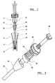
- Figure 1 shows a tamp assembly 2 positioned relative to a resected tibia 4 so as to tamp morcellised bone graft material 6 into the cavity 8 within the tibia, to receive the tibial component of a prosthetic knee joint.
- the assembly includes a distal tamp portion 10 which has a substantially constant circular cross-section with a diameter which corresponds approximately to the internal dimensions of the bone cavity. For a typical patient, the tamp diameter will be about 10 mm.
- the distal tamp portion extends continuously over a length of about 40 cm and has a substantially constant cross-section over that length.
- the end 12 of the distal tamp portion is rounded.
- a proximal tamp portion 14 has a through bore 16 extending through it, so that it can receive the distal tamp portion 10 to extend through it.
- the proximal tamp portion has an external cross-section at its distal end 18 which is approximately the same as the external cross-section of the distal tamp portion. It has an external surface 20 which flares outwardly towards its proximal end 22.
- the proximal tamp portion 14 is connected to a hammer 24 which also has a through bore extending through it, so that it too can receive the distal tamp portion 10 to extend through it. Both the proximal tamp portion and the hammer can be slid along the distal tamp portion.
- Figure 2 shows the assembly of the proximal tamp portion 14 and the hammer 24, positioned on the distal tamp portion (or guide shaft) 10. They are connected to one another by a releasible connection mechanism which allows them to be separated from one another. This allows different proximal tamp portions to be used during the course of a surgical procedure, to tamp layers of filler material successively in order to fill a bone cavity.
- the assembly includes a cap 26 which is threadably attached to the guide shaft at its top end.
- the cap 26 has to be removed from the guide shaft in order to allow the hammer and the proximal tamp portion to be removed from the guide shaft.
- the hammer 24 has a pair of circumferential flanges 28, 30 and a portion 32 between them with axially extending ridges, which enable the hammer to be gripped conveniently by a user.
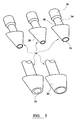
- FIG. 3 shows a plurality of proximal tamp portions 14 which can be used in the assembly of the invention. They differ from one another by having through bores 16 with different internal diameters, and by having differently shaped tamping surfaces 20.
- Each of the tamp portions includes a shaft 34 which terminates in a collar 36 at its upper end, which is received within the hammer.
- a groove 38 which extends between the tamping surface 20 and the collar 36 can be gripped by the hammer when the two are connected to one another.
- the height of the proximal tamp portions (measured along the axis of the through bore) will be arranged so that they can compress filler material to the desired depth within the bone cavity.
- Proximal tamp portions for one application for example for the tibial component of a knee joint prosthesis
- proximal tamp portions for another applicaiton for example the femoral component of a hip prosthesis.
- the height of the proximal tamp portions might be about 4 cm.
- Figure 4 shows a patient's tibia 4 in which the bone cavity 8 has been filled with filler material 6.
- the assembly 2 can be used to finish the upper surface of the bone assembly, using a cavity-end tamp portion 40.
- the cavity-end tamp portion has a planar tamping surface 42.
- a through bore 44 extends through the tamp portion, and is sized so that the tamp portion is a sliding fit over the guide shaft 10.
- the cavity-end tamp portion is connected to the hammer 24 so that the connected components can be slid on the guide shaft in a manner similar to the connected hammer and proximal tamp portion.
- Figure 5 is an enlarged view of a cavity-end tamp portion 40 in two parts.
- a first part 46 has the tamping surface 42 on its underside and the through bore 44 extending through it.
- a second adaptor part 48 can be connected rigidly to the first part and has formations 50 on it which enable it to be connected rigidly to the hammer 24.
- the configuration of the cavity-end tamp portion will depend on the application for the assembly and will generally be selected to correspond to the shape of the resected end of the bone, which might be, for example, the tibia or the femur in the case of a knee joint prosthesis, or the femur in the case of a hip joint prosthesis.
- a cavity within a resected bone is first prepared to receive an implant, for example using a reamer.
- the nature of the preparation will depend on the technique by which the implant is to be fixed into the bone cavity. It will also depend on the condition of the bone and the dimensions of the selected implant.
- a bone plug can be located in the bone cavity to restrict the depth to which filler material can be pushed into the cavity.
- the bone plug can have a threaded bore formed in it to receive a guide rod.
- a distal tamp portion is located in the bone cavity, with its tip located at an appropriate depth to define a cavity which will accommodate the selected implant. If the assembly is used with a guide rod extending from the bone plug, the distal tamp portion will be cannulated so as to be able to accommodate the guide rod. Filler material such as morcellised bone graft material is provided in the cavity, in the space between the distal tamp portion and the bone cavity wall.
- a proximal tamp portion is selected which will compact a thin layer of morcellised bone graft between it and the bone cavity wall, in the region of the cavity towards the resected end of the bone in which the cross-section of the cavity begins to increase in size. It is connected to the hammer and the connected components are slid onto the distal tamp portion at its free upper end. Filler material within the cavity is then compressed by moving the hammer and proximal tamp portion along the guide shaft provided by the distal tamp portion, using a repeated up and down action. The cap on the guide shaft prevents the hammer from being moved so far along the guide shaft that it comes off.
- the hammer and proximal tamp portion are removed from the guide shaft (after removing the cap if fitted).
- the tamp portion and is then separated from the hammer and replaced by another one which can be used to compress a thicker layer of filler material.
- This process is repeated until the filler material fills the cavity within the bone to define a space within the cavity which has an appropriate configuration to receive the selected implant.
- the hammer is then separated from the proximal tamp portion and is connected to a cavity-end tamp portion with an appropriate adaptor, which are used to finish the top surface of the filler material.
- the tamp assembly with any guide rod, is then removed from the bone cavity.
- the filler material that surrounds the distal tamp portion is only disturbed minimally when the distal tamp portion is removed. The disturbance that is suffers is less than would be the case if the distal tamp portion had been raised and lowered repeatedly, together with the proximal tamp portion and hammer.
Landscapes
- Health & Medical Sciences (AREA)
- Transplantation (AREA)
- Orthopedic Medicine & Surgery (AREA)
- Life Sciences & Earth Sciences (AREA)
- General Health & Medical Sciences (AREA)
- Oral & Maxillofacial Surgery (AREA)
- Engineering & Computer Science (AREA)
- Biomedical Technology (AREA)
- Heart & Thoracic Surgery (AREA)
- Vascular Medicine (AREA)
- Physical Education & Sports Medicine (AREA)
- Animal Behavior & Ethology (AREA)
- Cardiology (AREA)
- Public Health (AREA)
- Veterinary Medicine (AREA)
- Prostheses (AREA)
- Surgical Instruments (AREA)
- Control Of Motors That Do Not Use Commutators (AREA)
- Structures Of Non-Positive Displacement Pumps (AREA)
- Auxiliary Devices For And Details Of Packaging Control (AREA)
- Executing Machine-Instructions (AREA)
Applications Claiming Priority (2)
| Application Number | Priority Date | Filing Date | Title |
|---|---|---|---|
| GB0028445 | 2000-11-22 | ||
| GBGB0028445.5A GB0028445D0 (en) | 2000-11-22 | 2000-11-22 | A tamp assembly |
Publications (3)
| Publication Number | Publication Date |
|---|---|
| EP1208821A2 true EP1208821A2 (de) | 2002-05-29 |
| EP1208821A3 EP1208821A3 (de) | 2002-09-04 |
| EP1208821B1 EP1208821B1 (de) | 2004-07-07 |
Family
ID=9903641
Family Applications (1)
| Application Number | Title | Priority Date | Filing Date |
|---|---|---|---|
| EP20010309713 Expired - Lifetime EP1208821B1 (de) | 2000-11-22 | 2001-11-16 | Knochentransplantatverdichter |
Country Status (5)
| Country | Link |
|---|---|
| US (1) | US6656188B2 (de) |
| EP (1) | EP1208821B1 (de) |
| AT (1) | ATE270532T1 (de) |
| DE (1) | DE60104184T2 (de) |
| GB (1) | GB0028445D0 (de) |
Cited By (2)
| Publication number | Priority date | Publication date | Assignee | Title |
|---|---|---|---|---|
| EP1523965A3 (de) * | 2003-09-26 | 2005-11-09 | Depuy Products, Inc. | Knochenverdichter mit radialer Beaufschlagung |
| WO2021130372A1 (en) * | 2019-12-24 | 2021-07-01 | Depuy Ireland Unlimited Company | Surgical instruments and methods |
Families Citing this family (10)
| Publication number | Priority date | Publication date | Assignee | Title |
|---|---|---|---|---|
| US7329284B2 (en) * | 2002-09-27 | 2008-02-12 | Depuy Products, Inc. | Concave resurfacing prosthesis |
| WO2004112661A1 (en) * | 2003-06-20 | 2004-12-29 | Myers Thomas H | Method and apparatus for strengthening the biomechanical properties of implants |
| US7582090B2 (en) * | 2004-03-04 | 2009-09-01 | Wright Medical Technology, Inc. | Bone preserving total hip arthroplasty using autograft |
| US7749223B2 (en) * | 2004-08-09 | 2010-07-06 | Howmedica Osteonics Corp. | Navigated femoral axis finder |
| US7832405B1 (en) * | 2004-08-25 | 2010-11-16 | Biomet Manufacturing Corp. | Method and apparatus for assembling implants |
| US7925320B2 (en) | 2006-03-06 | 2011-04-12 | Garmin Switzerland Gmbh | Electronic device mount |
| US8348953B2 (en) * | 2008-01-10 | 2013-01-08 | Peter Brehm | Method and apparatus for impacting bone material |
| US10070969B2 (en) * | 2013-01-17 | 2018-09-11 | Stryker European Holdings I, Llc | Annulus plug for intervertebral disc repair |
| US10368895B2 (en) * | 2015-12-17 | 2019-08-06 | Olympus Corporation | Method for replacement arthroplasty |
| CN114028034A (zh) * | 2021-11-10 | 2022-02-11 | 上海市第六人民医院 | 一种易安装式髂骨翼填充块 |
Family Cites Families (13)
| Publication number | Priority date | Publication date | Assignee | Title |
|---|---|---|---|---|
| US5899907A (en) * | 1991-06-27 | 1999-05-04 | Johnson; Lanny L. | Instrumentation for proximal femoral compaction broaching |
| GB9202248D0 (en) * | 1992-02-03 | 1992-03-18 | Howmedica | Prosthesis for attachement without bone cement and method of attaching |
| US5690636A (en) * | 1995-12-21 | 1997-11-25 | Johnson & Johnson Professional, Inc. | Punch system for tibial prosthesis |
| US5718707A (en) | 1997-01-22 | 1998-02-17 | Mikhail; W. E. Michael | Method and apparatus for positioning and compacting bone graft |
| US5910172A (en) * | 1997-05-20 | 1999-06-08 | Johnson & Johnson | Apparatus for, and method of, preparing hip prosthesis implantation |
| GB9714003D0 (en) * | 1997-07-02 | 1997-09-10 | Howmedica | Apparatus for impacting bone chips in a bone canal |
| GB9714004D0 (en) * | 1997-07-02 | 1997-09-10 | Howmedica | Apparatus for releasably attaching an impaction hammer to a proximal impactor to be impacted into a bone |
| US5843086A (en) * | 1997-07-29 | 1998-12-01 | Stryker Corporation | Thermal bone cement removal system with tissue protector |
| US6126659A (en) * | 1998-09-30 | 2000-10-03 | Depuy Orthopaedics, Inc. | Impaction instruments |
| US6063091A (en) * | 1998-10-13 | 2000-05-16 | Stryker Technologies Corporation | Methods and tools for tibial intermedullary revision surgery and associated tibial components |
| GB9823308D0 (en) * | 1998-10-23 | 1998-12-23 | Benoist Girard & Cie | Prosthetic implant cement deflector |
| US6270502B1 (en) * | 1998-12-11 | 2001-08-07 | Smith & Nephew, Inc. | Methods and instruments for performing radial impacting |
| US6228092B1 (en) * | 1999-07-29 | 2001-05-08 | W. E. Michael Mikhail | System for performing hip prosthesis surgery |
-
2000
- 2000-11-22 GB GBGB0028445.5A patent/GB0028445D0/en not_active Ceased
-
2001
- 2001-11-16 AT AT01309713T patent/ATE270532T1/de not_active IP Right Cessation
- 2001-11-16 DE DE60104184T patent/DE60104184T2/de not_active Expired - Fee Related
- 2001-11-16 EP EP20010309713 patent/EP1208821B1/de not_active Expired - Lifetime
- 2001-11-21 US US09/989,067 patent/US6656188B2/en not_active Expired - Lifetime
Cited By (2)
| Publication number | Priority date | Publication date | Assignee | Title |
|---|---|---|---|---|
| EP1523965A3 (de) * | 2003-09-26 | 2005-11-09 | Depuy Products, Inc. | Knochenverdichter mit radialer Beaufschlagung |
| WO2021130372A1 (en) * | 2019-12-24 | 2021-07-01 | Depuy Ireland Unlimited Company | Surgical instruments and methods |
Also Published As
| Publication number | Publication date |
|---|---|
| US20020065518A1 (en) | 2002-05-30 |
| ATE270532T1 (de) | 2004-07-15 |
| EP1208821B1 (de) | 2004-07-07 |
| DE60104184D1 (de) | 2004-08-12 |
| GB0028445D0 (en) | 2001-01-10 |
| DE60104184T2 (de) | 2005-08-04 |
| EP1208821A3 (de) | 2002-09-04 |
| US6656188B2 (en) | 2003-12-02 |
Similar Documents
| Publication | Publication Date | Title |
|---|---|---|
| AU772169C (en) | Methods and instruments for radial bone impacting | |
| EP0595956B1 (de) | System zum durchführen einer revisionchirurgie an einer hüftprothese | |
| US5899907A (en) | Instrumentation for proximal femoral compaction broaching | |
| US6309395B1 (en) | Bone graft delivery surgical instruments | |
| EP1426013B1 (de) | System zur Wiederherstellung der Oberfläche einer Tibia | |
| EP0555004B1 (de) | Prothese für zementfreie Befestigung | |
| US5800437A (en) | Cannulated tamp and centering rod for total joint arthroplasty | |
| EP0992225B1 (de) | Verdichtungsinstrument | |
| US6656188B2 (en) | Tamp assembly | |
| US5928240A (en) | Apparatus for forming a centered bore for the femoral stem of a hip prosthesis | |
| JPS639465B2 (de) | ||
| CN102014800A (zh) | 局部关节表面置换植入物、仪器和方法 | |
| EP1523965B1 (de) | Medizinischer Knochenverdichter | |
| WO2022261354A2 (en) | Orthopedic implants and tools | |
| EP1413263A1 (de) | Prothetisches Implantat | |
| GB2217608A (en) | Hip prosthesis | |
| US7824409B2 (en) | Modular impaction grafting tamps | |
| JPS58190438A (ja) | 関節接合補綴の移植 | |
| EP0783275B1 (de) | Zuführwerkzeug zur verdichteten räumung des proximalen femoralschaftes | |
| JPS5990558A (ja) | 髄内栓 | |
| EP1210018B1 (de) | Knochentransplantatverdichter | |
| CA2200201C (en) | Instrumentation for proximal femoral compaction broaching |
Legal Events
| Date | Code | Title | Description |
|---|---|---|---|
| PUAI | Public reference made under article 153(3) epc to a published international application that has entered the european phase |
Free format text: ORIGINAL CODE: 0009012 |
|
| AK | Designated contracting states |
Kind code of ref document: A2 Designated state(s): AT BE CH CY DE DK ES FI FR GB GR IE IT LI LU MC NL PT SE TR |
|
| AX | Request for extension of the european patent |
Free format text: AL;LT;LV;MK;RO;SI |
|
| PUAL | Search report despatched |
Free format text: ORIGINAL CODE: 0009013 |
|
| AK | Designated contracting states |
Kind code of ref document: A3 Designated state(s): AT BE CH CY DE DK ES FI FR GB GR IE IT LI LU MC NL PT SE TR |
|
| AX | Request for extension of the european patent |
Free format text: AL;LT;LV;MK;RO;SI |
|
| 17P | Request for examination filed |
Effective date: 20030116 |
|
| AKX | Designation fees paid |
Designated state(s): AT BE CH CY DE DK ES FI FR GB GR IE IT LI LU MC NL PT SE TR |
|
| 17Q | First examination report despatched |
Effective date: 20030516 |
|
| GRAP | Despatch of communication of intention to grant a patent |
Free format text: ORIGINAL CODE: EPIDOSNIGR1 |
|
| GRAS | Grant fee paid |
Free format text: ORIGINAL CODE: EPIDOSNIGR3 |
|
| GRAA | (expected) grant |
Free format text: ORIGINAL CODE: 0009210 |
|
| AK | Designated contracting states |
Kind code of ref document: B1 Designated state(s): AT BE CH CY DE DK ES FI FR GB GR IE IT LI LU MC NL PT SE TR |
|
| PG25 | Lapsed in a contracting state [announced via postgrant information from national office to epo] |
Ref country code: IT Free format text: LAPSE BECAUSE OF FAILURE TO SUBMIT A TRANSLATION OF THE DESCRIPTION OR TO PAY THE FEE WITHIN THE PRESCRIBED TIME-LIMIT;WARNING: LAPSES OF ITALIAN PATENTS WITH EFFECTIVE DATE BEFORE 2007 MAY HAVE OCCURRED AT ANY TIME BEFORE 2007. THE CORRECT EFFECTIVE DATE MAY BE DIFFERENT FROM THE ONE RECORDED. Effective date: 20040707 Ref country code: FI Free format text: LAPSE BECAUSE OF FAILURE TO SUBMIT A TRANSLATION OF THE DESCRIPTION OR TO PAY THE FEE WITHIN THE PRESCRIBED TIME-LIMIT Effective date: 20040707 Ref country code: NL Free format text: LAPSE BECAUSE OF FAILURE TO SUBMIT A TRANSLATION OF THE DESCRIPTION OR TO PAY THE FEE WITHIN THE PRESCRIBED TIME-LIMIT Effective date: 20040707 Ref country code: AT Free format text: LAPSE BECAUSE OF FAILURE TO SUBMIT A TRANSLATION OF THE DESCRIPTION OR TO PAY THE FEE WITHIN THE PRESCRIBED TIME-LIMIT Effective date: 20040707 Ref country code: TR Free format text: LAPSE BECAUSE OF FAILURE TO SUBMIT A TRANSLATION OF THE DESCRIPTION OR TO PAY THE FEE WITHIN THE PRESCRIBED TIME-LIMIT Effective date: 20040707 Ref country code: BE Free format text: LAPSE BECAUSE OF FAILURE TO SUBMIT A TRANSLATION OF THE DESCRIPTION OR TO PAY THE FEE WITHIN THE PRESCRIBED TIME-LIMIT Effective date: 20040707 Ref country code: CY Free format text: LAPSE BECAUSE OF FAILURE TO SUBMIT A TRANSLATION OF THE DESCRIPTION OR TO PAY THE FEE WITHIN THE PRESCRIBED TIME-LIMIT Effective date: 20040707 |
|
| REG | Reference to a national code |
Ref country code: GB Ref legal event code: FG4D |
|
| REG | Reference to a national code |
Ref country code: CH Ref legal event code: EP |
|
| REG | Reference to a national code |
Ref country code: IE Ref legal event code: FG4D |
|
| REF | Corresponds to: |
Ref document number: 60104184 Country of ref document: DE Date of ref document: 20040812 Kind code of ref document: P |
|
| REG | Reference to a national code |
Ref country code: CH Ref legal event code: NV Representative=s name: E. BLUM & CO. PATENTANWAELTE |
|
| PG25 | Lapsed in a contracting state [announced via postgrant information from national office to epo] |
Ref country code: GR Free format text: LAPSE BECAUSE OF FAILURE TO SUBMIT A TRANSLATION OF THE DESCRIPTION OR TO PAY THE FEE WITHIN THE PRESCRIBED TIME-LIMIT Effective date: 20041007 Ref country code: DK Free format text: LAPSE BECAUSE OF FAILURE TO SUBMIT A TRANSLATION OF THE DESCRIPTION OR TO PAY THE FEE WITHIN THE PRESCRIBED TIME-LIMIT Effective date: 20041007 Ref country code: SE Free format text: LAPSE BECAUSE OF FAILURE TO SUBMIT A TRANSLATION OF THE DESCRIPTION OR TO PAY THE FEE WITHIN THE PRESCRIBED TIME-LIMIT Effective date: 20041007 |
|
| PG25 | Lapsed in a contracting state [announced via postgrant information from national office to epo] |
Ref country code: ES Free format text: LAPSE BECAUSE OF FAILURE TO SUBMIT A TRANSLATION OF THE DESCRIPTION OR TO PAY THE FEE WITHIN THE PRESCRIBED TIME-LIMIT Effective date: 20041018 |
|
| PG25 | Lapsed in a contracting state [announced via postgrant information from national office to epo] |
Ref country code: LU Free format text: LAPSE BECAUSE OF NON-PAYMENT OF DUE FEES Effective date: 20041116 |
|
| PG25 | Lapsed in a contracting state [announced via postgrant information from national office to epo] |
Ref country code: MC Free format text: LAPSE BECAUSE OF NON-PAYMENT OF DUE FEES Effective date: 20041130 |
|
| NLV1 | Nl: lapsed or annulled due to failure to fulfill the requirements of art. 29p and 29m of the patents act | ||
| ET | Fr: translation filed | ||
| PLBE | No opposition filed within time limit |
Free format text: ORIGINAL CODE: 0009261 |
|
| STAA | Information on the status of an ep patent application or granted ep patent |
Free format text: STATUS: NO OPPOSITION FILED WITHIN TIME LIMIT |
|
| 26N | No opposition filed |
Effective date: 20050408 |
|
| REG | Reference to a national code |
Ref country code: CH Ref legal event code: PFA Owner name: DEPUY INTERNATIONAL LIMITED Free format text: DEPUY INTERNATIONAL LIMITED#ST. ANTHONYS ROAD#BEESTON, LEEDS LS11 8DT (GB) -TRANSFER TO- DEPUY INTERNATIONAL LIMITED#ST. ANTHONYS ROAD#BEESTON, LEEDS LS11 8DT (GB) |
|
| PG25 | Lapsed in a contracting state [announced via postgrant information from national office to epo] |
Ref country code: PT Free format text: LAPSE BECAUSE OF NON-PAYMENT OF DUE FEES Effective date: 20041207 |
|
| PGFP | Annual fee paid to national office [announced via postgrant information from national office to epo] |
Ref country code: CH Payment date: 20081130 Year of fee payment: 8 Ref country code: DE Payment date: 20081114 Year of fee payment: 8 Ref country code: IE Payment date: 20081114 Year of fee payment: 8 |
|
| PGFP | Annual fee paid to national office [announced via postgrant information from national office to epo] |
Ref country code: FR Payment date: 20081112 Year of fee payment: 8 |
|
| PGFP | Annual fee paid to national office [announced via postgrant information from national office to epo] |
Ref country code: GB Payment date: 20081112 Year of fee payment: 8 |
|
| REG | Reference to a national code |
Ref country code: CH Ref legal event code: PL |
|
| GBPC | Gb: european patent ceased through non-payment of renewal fee |
Effective date: 20091116 |
|
| REG | Reference to a national code |
Ref country code: IE Ref legal event code: MM4A |
|
| REG | Reference to a national code |
Ref country code: FR Ref legal event code: ST Effective date: 20100730 |
|
| PG25 | Lapsed in a contracting state [announced via postgrant information from national office to epo] |
Ref country code: IE Free format text: LAPSE BECAUSE OF NON-PAYMENT OF DUE FEES Effective date: 20091116 Ref country code: LI Free format text: LAPSE BECAUSE OF NON-PAYMENT OF DUE FEES Effective date: 20091130 Ref country code: CH Free format text: LAPSE BECAUSE OF NON-PAYMENT OF DUE FEES Effective date: 20091130 Ref country code: FR Free format text: LAPSE BECAUSE OF NON-PAYMENT OF DUE FEES Effective date: 20091130 |
|
| PG25 | Lapsed in a contracting state [announced via postgrant information from national office to epo] |
Ref country code: DE Free format text: LAPSE BECAUSE OF NON-PAYMENT OF DUE FEES Effective date: 20100601 |
|
| PG25 | Lapsed in a contracting state [announced via postgrant information from national office to epo] |
Ref country code: GB Free format text: LAPSE BECAUSE OF NON-PAYMENT OF DUE FEES Effective date: 20091116 |