EP1208882A2 - Arrangement de support d'une roue d'un patin à roulettes - Google Patents
Arrangement de support d'une roue d'un patin à roulettes Download PDFInfo
- Publication number
- EP1208882A2 EP1208882A2 EP01127572A EP01127572A EP1208882A2 EP 1208882 A2 EP1208882 A2 EP 1208882A2 EP 01127572 A EP01127572 A EP 01127572A EP 01127572 A EP01127572 A EP 01127572A EP 1208882 A2 EP1208882 A2 EP 1208882A2
- Authority
- EP
- European Patent Office
- Prior art keywords
- bracket
- frame
- wheel
- roller skate
- hole
- Prior art date
- Legal status (The legal status is an assumption and is not a legal conclusion. Google has not performed a legal analysis and makes no representation as to the accuracy of the status listed.)
- Withdrawn
Links
- 230000008878 coupling Effects 0.000 description 2
- 238000010168 coupling process Methods 0.000 description 2
- 238000005859 coupling reaction Methods 0.000 description 2
- 238000007792 addition Methods 0.000 description 1
- 230000002411 adverse Effects 0.000 description 1
- 230000006872 improvement Effects 0.000 description 1
- 230000004048 modification Effects 0.000 description 1
- 238000012986 modification Methods 0.000 description 1
- 238000006467 substitution reaction Methods 0.000 description 1
Images


Classifications
-
- A—HUMAN NECESSITIES
- A63—SPORTS; GAMES; AMUSEMENTS
- A63C—SKATES; SKIS; ROLLER SKATES; DESIGN OR LAYOUT OF COURTS, RINKS OR THE LIKE
- A63C17/00—Roller skates; Skate-boards
-
- A—HUMAN NECESSITIES
- A63—SPORTS; GAMES; AMUSEMENTS
- A63C—SKATES; SKIS; ROLLER SKATES; DESIGN OR LAYOUT OF COURTS, RINKS OR THE LIKE
- A63C17/00—Roller skates; Skate-boards
- A63C17/008—Roller skates; Skate-boards with retractable wheel, i.e. movable relative to the chassis out of contact from surface
-
- A—HUMAN NECESSITIES
- A63—SPORTS; GAMES; AMUSEMENTS
- A63C—SKATES; SKIS; ROLLER SKATES; DESIGN OR LAYOUT OF COURTS, RINKS OR THE LIKE
- A63C17/00—Roller skates; Skate-boards
- A63C17/20—Roller skates; Skate-boards with fixable wheels permitting the skates to be used for walking
Definitions
- the present invention relates to an improvement of a structure for supporting a wheel of a roller skate, and, more particularly, to a structure for supporting a wheel of a roller skate which enables a wheel coupled to an outsole of a roller skate to be supported and retracted simply and reliably, thereby improving reliability of operation of a roller support structure.
- a frame 60 consisting of a pair of box containers having a predetermined width and connecting walls fixedly disposed between the two box containers, all of which are integrally formed, is attached to an outsole 20.
- Each of the box containers is provided at its both side plates with curved and elongated slide holes 61 and locking holes 62 such that the slide holes 61 and the locking holes 62 formed at the both side plates of the box container are aligned with each other.
- a bracket 30 adapted to rotatably support a wheel 50 can be received in the receiving room of the box container.
- a rectangular base plate 70 is rotatably coupled to an upper surface of the bracket 30 by means of a coupling pin 40.
- the base plate 70 is provided at a side, i.e. at a front side or rear side, with a pair of swing pins 71 facing each other, and at the other side with a pair of locking protrusions 72 to be biased outwardly. Therefore, the swing pins 71 are fitted in the slide holes 61 so that they can be moved up and down within a predetermined range corresponding to the length of the slide holes 61.
- the biased locking protrusions 72 are releasably fitted in the locking holes 62 of the frame 60.
- Such a conventional structure for supporting a wheel of a roller skate is designed to allow the base plate 70 to swing about the swing pins 71.
- the bracket 30 and the wheel 50 are first drawn from the receiving room of the box container.
- a lower surface of the base plate 70 is registered with a virtual plane defined by bottom edges of the frame 60 so that the bracket 30 coupled to the lower surface of the base plate 70 can be rotated about the coupling pin 40.
- the locking protrusions 72 are slightly moved upward such that the locking protrusions 72 are fitted into the locking holes 62.
- both the locking protrusions 72 are first compressed inwardly and then slightly drawn downward. Subsequently, the bracket 30 is rotated 90° and again pushed upward. Consequently, the bracket 30 and the base plate 70 are turned about the slide pins 71 to be receiving into the received room.
- the bracket 30 is provided at its lower surface with a locking pin 33 which is biased outward by a spring, and the box container of the frame 60 is formed with a second locking hole 63 corresponding to the locking pin 33. Therefore, when the bracket 30 and the wheel 50 are received in the receiving room, the second locking pin 33 is fitted into the corresponding locking hole 63 of the frame 60, thereby causing the bracket 30 to be stably maintained therein.
- the above-mentioned conventional structure for supporting a wheel has disadvantages in that the supporting structure is somewhat coarse and complicated because the base plate 70 is supported by the rocking protrusions 72 and the swing pins 71 and the bracket 30 is supported by the second locking pin 33; and the wheel 50 rattles because the swing pins 71 can be moved along the slide elongated holes 61, thereby causing unpleasant noise that may adversely affecting reliability of products.
- an object of the present invention is to provide a structure for supporting a wheel of a roller skate which enables a wheel coupled to an outsole of a roller skate to be supported and retracted simply and reliably.
- the present invention provides a structure for supporting a wheel of a roller skate which includes a box-shaped frame attached to an outsole of the roller skate, which has at its bottom wall fitting recesses and at its side wall a passage opening; a swing plate pivotally connected to the frame; and a bracket rotatably coupled to the swing plate, which can be elastically spaced from the swing plate by elastic means and has a fitting protrusion to be fitted in the recesses of the frame, whereby the bracket can be pulled out of the fitting recesses and rotated 90° followed by being pushed into the frame through the passage opening.
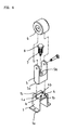
- Figs. 4 to 6 show structures for supporting wheels of a roller skate according to the present invention.
- an outsole 2 of a roller skate to which a structure according to the present invention is attached is formed with rectangular receiving rooms 2a at appropriate positions.
- Each of the receiving rooms 2a receives a base frame 1 therein.
- the base frame 1 is shaped into a box shape with an upper side and a front or a rear side opened, and provided at its both upper ends with flanges 1a each having a screw hole.
- the frame 1 can be fixedly attached to the outsole 2 of the roller skate by tightening screws into the outsole 2 through the screw holes.
- the frame 1 is formed at its bottom surface with a pair of protrusions 1b which are slightly extended inwardly to face each other.
- the bottom surface of the frame 1 is formed at its both sides with fitting recesses 1c. Therefore, the bottom surface of the frame 1 has a "T"-shaped cut portion.
- a pair of vertical walls are provided at its front or rear side with hinge pins 4a, respectively, and a swing plate 4 is pivotally coupled to the frame 1 via the hinge pins 4a.
- a bracket 5 is rotatably coupled to the swing plate 4.
- the bracket 5 has a pair of arms extended downward, between which a wheel 6 is rotatably supported.
- the bracket 5 has at its top surface a crosswise protrusion 5a which is adapted to be releasably fitted in the fitting recesses 1c of the frame 1.
- the bracket 5 is formed at its top wall with a counterbored through hole 5b.
- a bolt stud 8 is threaded into the counterbored through hole 5b through a coil spring 7 interposed therebetween so that the coil spring 7 is disposed between a bolt head seat of the counterbored hole 5b and a head of the bolt stud 8.
- the swing plate 4 is centrally formed with a threaded hole 4b such that a lower end of the bolt stud 8 can be releasably threaded into the threaded hole 4b.
- the top protrusion 5a of the bracket 5 is fitted into the fitting recesses 1c formed at the lower end of the frame 1, and shoulders disposed at both sides of the top protrusion 5a are engaged with the protrusions 1b and the bottom surface of the frame 1, thereby preventing the bracket 5 from being moved back and forth.
- the bracket 5 since the bracket 5 is upward biased by the coil spring 7 interposed between the bracket 5 and the bolt stud 8, the bracket 5 can be more securely attached to the frame 1.
- the top protrusion 5a of the bracket 5 is taken out of the fitting recesses 1c of the frame 1 while compressing the coil spring 7, thereby allowing the bracket 5 to be rotated about the bolt stud 8.
- the bracket 5 is rotated 90° in a state of being out of the fitting recesses 1c, the top protrusion 5a of the bracket 5 comes into contact with the swing plate 4 at its side. Thereafter, as the swing plate 4 is turned upward about the hinge pin 4a, the bracket 5 and the wheel 6 which are coupled to the swing plate 4 are received in the receiving room 2a of the outsole 2.
- the bracket 5 is closely fitted between the facing protrusions 1b of the frame 1, thereby causing the wheel 6 to be maintained in the receiving room 2a.
- the coil spring 7 is designed to have an elasticity sufficient to cause the swing plate 4 and the bracket 5 to be strongly coupled to each other.
- the protrusions 1b formed at the bottom end of the frame 1 are extended inwardly such that the protrusions 1b have a predetermined spacing therebetween to allow the rotated bracket 5 to be passed therethrough.
- the present invention provides a structure for supporting a wheel of a roller skate which enables a bracket and a wheel to be retracted into a receiving room of an outsole of the roller skate easily and reliably by a simple operation of pulling and turning the bracket or the wheel 90° and then pushing it into the receiving room of the outsole. By carrying out the operation in reverse, the wheel can be extended from the receiving room without difficulty. Furthermore, since the bracket is subjected to elasticity of a coil spring, the top portion of the bracket can be coupled to a frame more stably and securely.
Landscapes
- Footwear And Its Accessory, Manufacturing Method And Apparatuses (AREA)
Applications Claiming Priority (2)
| Application Number | Priority Date | Filing Date | Title |
|---|---|---|---|
| KR2000032287 | 2000-11-18 | ||
| KR2020000032287U KR200222386Y1 (ko) | 2000-11-18 | 2000-11-18 | 롤러스케이트의 롤러 지지구조 |
Publications (2)
| Publication Number | Publication Date |
|---|---|
| EP1208882A2 true EP1208882A2 (fr) | 2002-05-29 |
| EP1208882A3 EP1208882A3 (fr) | 2003-05-28 |
Family
ID=19671786
Family Applications (1)
| Application Number | Title | Priority Date | Filing Date |
|---|---|---|---|
| EP01127572A Withdrawn EP1208882A3 (fr) | 2000-11-18 | 2001-11-19 | Arrangement de support d'une roue d'un patin à roulettes |
Country Status (4)
| Country | Link |
|---|---|
| US (1) | US20020060435A1 (fr) |
| EP (1) | EP1208882A3 (fr) |
| JP (1) | JP3086094U (fr) |
| KR (1) | KR200222386Y1 (fr) |
Families Citing this family (7)
| Publication number | Priority date | Publication date | Assignee | Title |
|---|---|---|---|---|
| JP2697801B2 (ja) * | 1991-10-17 | 1998-01-14 | 株式会社クボタ | 浄化槽 |
| US7063336B2 (en) | 1999-04-01 | 2006-06-20 | Heeling Sports Limited | External wheeled heeling apparatus and method |
| HK1041421B (en) * | 1999-04-01 | 2004-02-06 | Heeling Sports Limited | Heeling apparatus and method |
| US6631911B2 (en) * | 2001-05-30 | 2003-10-14 | Ching-Long Chen | Combined structure of a sports shoe and an in-line skate |
| JP2008508953A (ja) | 2004-08-04 | 2008-03-27 | ヒーリング・スポーツ・リミテッド | 電動移動具及び電動移動方法 |
| US20090107008A1 (en) * | 2007-10-31 | 2009-04-30 | Yu-Chun Chou | Integral shoe with roller assembly |
| US10945485B2 (en) | 2012-08-03 | 2021-03-16 | Heeling Sports Limited | Heeling apparatus |
Citations (1)
| Publication number | Priority date | Publication date | Assignee | Title |
|---|---|---|---|---|
| KR200237495Y1 (ko) | 2000-10-25 | 2001-10-25 | 김정재 | 롤러스케이트의 롤러 지지구조 |
Family Cites Families (5)
| Publication number | Priority date | Publication date | Assignee | Title |
|---|---|---|---|---|
| US584089A (en) * | 1897-06-08 | Julius buttermilch | ||
| US2719724A (en) * | 1953-08-11 | 1955-10-04 | Lundgren Robert | Roller skate with spring biased steerably interconnected tandem wheels |
| IT1226672B (it) * | 1988-12-28 | 1991-01-31 | Sisler Remo | Dispositivo autodifferenziatore di assetto per ruote orientabili di carrelli a conduzione manuale |
| US6065762A (en) * | 1998-03-11 | 2000-05-23 | Brelvi; Nazir A | Multidirectional in-line roller skate |
| US6120039A (en) * | 1999-08-16 | 2000-09-19 | Clementi; Fred | Walking and in-line skate shoe |
-
2000
- 2000-11-18 KR KR2020000032287U patent/KR200222386Y1/ko not_active Expired - Fee Related
-
2001
- 2001-11-16 JP JP2001007519U patent/JP3086094U/ja not_active Expired - Fee Related
- 2001-11-19 EP EP01127572A patent/EP1208882A3/fr not_active Withdrawn
- 2001-11-19 US US09/995,981 patent/US20020060435A1/en not_active Abandoned
Patent Citations (1)
| Publication number | Priority date | Publication date | Assignee | Title |
|---|---|---|---|---|
| KR200237495Y1 (ko) | 2000-10-25 | 2001-10-25 | 김정재 | 롤러스케이트의 롤러 지지구조 |
Also Published As
| Publication number | Publication date |
|---|---|
| EP1208882A3 (fr) | 2003-05-28 |
| JP3086094U (ja) | 2002-05-31 |
| US20020060435A1 (en) | 2002-05-23 |
| KR200222386Y1 (ko) | 2001-05-02 |
Similar Documents
| Publication | Publication Date | Title |
|---|---|---|
| US7240685B2 (en) | Side rail assembly for a canopy including a side rail having a hook for engaging a side rail connector on an upright of the canopy | |
| US5024359A (en) | Bicycle cooler | |
| US7748680B2 (en) | Foldable stand for display device | |
| US20020104155A1 (en) | Combined adult and children's toilet seat assembly | |
| US20050061940A1 (en) | Retractable hook assembly for mounting on a surface | |
| US20050193520A1 (en) | Door stop | |
| USD467400S1 (en) | Clothes peg | |
| EP1208882A2 (fr) | Arrangement de support d'une roue d'un patin à roulettes | |
| US6003691A (en) | Tool rack | |
| US20020000500A1 (en) | Golf bag support device | |
| US6282827B1 (en) | Picture frame and stand therefor | |
| US5860759A (en) | Connector for frame members | |
| US5876289A (en) | Safety swing seat mounting structure | |
| CN201043667Y (zh) | 具快速装卸功能的支撑装置 | |
| CN107204508B (zh) | 一种平板天线支座 | |
| US6598240B1 (en) | Toilet seat device having support for children | |
| US20030048051A1 (en) | Silding track structure | |
| CN2423638Y (zh) | 薄型显示装置的结合装置 | |
| CN206409067U (zh) | 具有自动复位门闩机构的保险柜 | |
| JPH09158589A (ja) | ドアストッパ− | |
| CN222823124U (zh) | 一种通用性高的柜体平开门 | |
| CN211025109U (zh) | 一种不倒翁玩具 | |
| EP1059046A1 (fr) | Sac avec structure de réception pour téléphone portatif | |
| JP2550344Y2 (ja) | 学習机用パネル保持枠 | |
| KR900009437Y1 (ko) | 절첩테이블의 경첩 |
Legal Events
| Date | Code | Title | Description |
|---|---|---|---|
| PUAI | Public reference made under article 153(3) epc to a published international application that has entered the european phase |
Free format text: ORIGINAL CODE: 0009012 |
|
| AK | Designated contracting states |
Kind code of ref document: A2 Designated state(s): AT BE CH CY DE DK ES FI FR GB GR IE IT LI LU MC NL PT SE TR |
|
| AX | Request for extension of the european patent |
Free format text: AL;LT;LV;MK;RO;SI |
|
| PUAL | Search report despatched |
Free format text: ORIGINAL CODE: 0009013 |
|
| AK | Designated contracting states |
Designated state(s): AT BE CH CY DE DK ES FI FR GB GR IE IT LI LU MC NL PT SE TR |
|
| AX | Request for extension of the european patent |
Extension state: AL LT LV MK RO SI |
|
| AKX | Designation fees paid | ||
| REG | Reference to a national code |
Ref country code: DE Ref legal event code: 8566 |
|
| STAA | Information on the status of an ep patent application or granted ep patent |
Free format text: STATUS: THE APPLICATION IS DEEMED TO BE WITHDRAWN |
|
| 18D | Application deemed to be withdrawn |
Effective date: 20031129 |