EP1208935A1 - Support pour une tôle - Google Patents
Support pour une tôle Download PDFInfo
- Publication number
- EP1208935A1 EP1208935A1 EP01108539A EP01108539A EP1208935A1 EP 1208935 A1 EP1208935 A1 EP 1208935A1 EP 01108539 A EP01108539 A EP 01108539A EP 01108539 A EP01108539 A EP 01108539A EP 1208935 A1 EP1208935 A1 EP 1208935A1
- Authority
- EP
- European Patent Office
- Prior art keywords
- sheet metal
- sheet
- needles
- support areas
- support
- Prior art date
- Legal status (The legal status is an assumption and is not a legal conclusion. Google has not performed a legal analysis and makes no representation as to the accuracy of the status listed.)
- Withdrawn
Links
- 239000000463 material Substances 0.000 title claims abstract description 28
- 229910052751 metal Inorganic materials 0.000 claims abstract description 74
- 239000002184 metal Substances 0.000 claims abstract description 74
- 238000003698 laser cutting Methods 0.000 claims description 6
- 229910000831 Steel Inorganic materials 0.000 claims description 4
- 238000011109 contamination Methods 0.000 claims description 4
- 238000002844 melting Methods 0.000 claims description 4
- 239000002923 metal particle Substances 0.000 claims description 4
- 229910001220 stainless steel Inorganic materials 0.000 claims description 4
- 239000010935 stainless steel Substances 0.000 claims description 4
- 239000010959 steel Substances 0.000 claims description 4
- WFKWXMTUELFFGS-UHFFFAOYSA-N tungsten Chemical compound [W] WFKWXMTUELFFGS-UHFFFAOYSA-N 0.000 claims description 4
- 229910052721 tungsten Inorganic materials 0.000 claims description 4
- 239000010937 tungsten Substances 0.000 claims description 4
- RYGMFSIKBFXOCR-UHFFFAOYSA-N Copper Chemical compound [Cu] RYGMFSIKBFXOCR-UHFFFAOYSA-N 0.000 claims description 3
- 229910052802 copper Inorganic materials 0.000 claims description 3
- 239000010949 copper Substances 0.000 claims description 3
- 230000008018 melting Effects 0.000 claims description 3
- 238000000034 method Methods 0.000 claims description 3
- VNNRSPGTAMTISX-UHFFFAOYSA-N chromium nickel Chemical compound [Cr].[Ni] VNNRSPGTAMTISX-UHFFFAOYSA-N 0.000 claims description 2
- 230000002950 deficient Effects 0.000 claims description 2
- 239000000126 substance Substances 0.000 claims description 2
- 239000007769 metal material Substances 0.000 claims 1
- 238000005520 cutting process Methods 0.000 description 9
- PXHVJJICTQNCMI-UHFFFAOYSA-N Nickel Chemical compound [Ni] PXHVJJICTQNCMI-UHFFFAOYSA-N 0.000 description 5
- 239000002245 particle Substances 0.000 description 4
- 239000002699 waste material Substances 0.000 description 4
- 229910052759 nickel Inorganic materials 0.000 description 3
- VYZAMTAEIAYCRO-UHFFFAOYSA-N Chromium Chemical compound [Cr] VYZAMTAEIAYCRO-UHFFFAOYSA-N 0.000 description 2
- ZOKXTWBITQBERF-UHFFFAOYSA-N Molybdenum Chemical group [Mo] ZOKXTWBITQBERF-UHFFFAOYSA-N 0.000 description 1
- 238000010586 diagram Methods 0.000 description 1
- 230000020169 heat generation Effects 0.000 description 1
- 239000000155 melt Substances 0.000 description 1
- 239000012768 molten material Substances 0.000 description 1
- 229910052750 molybdenum Inorganic materials 0.000 description 1
- 239000011733 molybdenum Substances 0.000 description 1
- 230000000737 periodic effect Effects 0.000 description 1
- 230000000246 remedial effect Effects 0.000 description 1
- 238000009958 sewing Methods 0.000 description 1
- 239000007787 solid Substances 0.000 description 1
- 238000003860 storage Methods 0.000 description 1
- 230000001960 triggered effect Effects 0.000 description 1
- 238000003466 welding Methods 0.000 description 1
Images


Classifications
-
- B—PERFORMING OPERATIONS; TRANSPORTING
- B23—MACHINE TOOLS; METAL-WORKING NOT OTHERWISE PROVIDED FOR
- B23K—SOLDERING OR UNSOLDERING; WELDING; CLADDING OR PLATING BY SOLDERING OR WELDING; CUTTING BY APPLYING HEAT LOCALLY, e.g. FLAME CUTTING; WORKING BY LASER BEAM
- B23K26/00—Working by laser beam, e.g. welding, cutting or boring
- B23K26/70—Auxiliary operations or equipment
- B23K26/702—Auxiliary equipment
-
- B—PERFORMING OPERATIONS; TRANSPORTING
- B23—MACHINE TOOLS; METAL-WORKING NOT OTHERWISE PROVIDED FOR
- B23K—SOLDERING OR UNSOLDERING; WELDING; CLADDING OR PLATING BY SOLDERING OR WELDING; CUTTING BY APPLYING HEAT LOCALLY, e.g. FLAME CUTTING; WORKING BY LASER BEAM
- B23K26/00—Working by laser beam, e.g. welding, cutting or boring
- B23K26/20—Bonding
- B23K26/21—Bonding by welding
Definitions
- the invention relates to a base for sheet metal, the through one arranged above the sheet and onto the sheet focused laser device is severed according to the Preamble of claim 1.
- Document provided movement devices so that the Laser device can be guided over the desired interfaces can. This can be straight or curved Cuts, or quasi-holes through round Cut out act.
- the laser device is stationary and the sheet is placed over the corresponding supports desired sections in two mutually perpendicular Directions moved.
- Gap provided so that damage to the pad or Contamination of the underside of the sheet can be avoided.
- the Moving heavy masses at the desired high speed leads to inaccuracies. Therefore, this is preferred Moving the relatively light laser device above a stationary sheet metal base.
- the problem that the laser beam also supports the Sheet affected, so that after a relatively short Through a large number of molten sheet particles Sparks etc. stick.
- the one on the sheet metal underside The molten sheet metal parts that come into contact with it have to be laboriously subsequent procedures are removed.
- the document itself is usually only temperature-resistant for a short time, resulting in melting of the same and relatively shorter Service life. The use of high temperature resistant Materiales are excluded for cost reasons.
- DE 44 46 975 A1 is a support grid for workpieces described, which consist for example of support pins can, which are stored on the lower beams lined up side by side can be.
- These support pins are relatively wide and conical, so that there is a risk that through the Sheet material sprayed through the laser by is reflected on the underside of the sheet at the bottom.
- the Support pins hold when they meet a laser beam cutting point did not stand and have been exposed to heat correspondingly short lifespan.
- the laser processing head can only be moved in a single straight line, in one order 90 ° offset direction is a corresponding straight line Movement of the table pad provided, the cutting itself takes place in a single cutting location.
- the invention relates in particular to a fall of at most one or two points stored sheet metal pieces and the removal the same.
- When cutting through the last point of the sheet metal part to be cut tilts down and causes an unclean cutting surface on this End section, resulting in a loss of quality and one Post-treatment leads.
- JP 63-52 790 A Patent Abstracts of Japan M-723,1988, vol. 12, No. 269, describes one with a support grid two-part support pin, the upper part of one conical insert made of high-melting material such as There is molybdenum or tungsten.
- the wide bevel and the low cone height lead to a reflection of melted down by the laser device Material on the underside of the sheet.
- the cone-shaped needle tip has a pin at the bottom, which is in the actual hollow cylindrical needle is inserted.
- the structure is relative wide and not exactly adjustable.
- the relatively wide Cone base does not allow for space reasons, also very much small pieces of sheet metal, down to less than a square centimeter Area to be stably supported by three points.
- the invention has for its object a base for Sheet according to the preamble of claim 1 so to design that the life increases and a Damage to the underside of the sheet is avoided, in particular in the case of a movable laser device via a stationary sheet metal support.
- the rest of the material namely for the metal strips, can be made from stainless steel such as chrome nickel steel. This means, however, that after a long period of operation the the kerf of the machined sheet blown out, flung away and hitting the sheet metal strip very much hot sheet metal particles heated by the cutting process, namely the laser cutting waste, on certain parts of the Fix the sheet metal support, namely on the sheet metal strips. More particles can adhere to this over time build up, for example welded to the underlay, so that the increased arrangement of the needle tips over the Support areas are leveled to the extent that, contrary to the The aim of the invention is to return waste particles to the Sheet metal underside can hit, what to the mentioned Can cause damage.
- This material is said to be significantly different from the material of the processed sheet, which is usually for the intended main use of stainless steel respectively Chromium-nickel steel can exist. This material is said to be so be chosen to match the hot ones Sheet metal particles of the laser kerf no chemical and / or physical connection, for example, melts, welds etc.
- the needles placed on the integrated support areas protrude about one to ten centimeters from the support areas upwards, preferably two and a half to three and a half Centimeter. This distance is usually sufficient to be safe exclude damage to the metal strips, namely not only the deepened furrows, but also the higher ones Support areas. These areas are also on the the minimum required area is limited to one Safe defined storage of the individual needles in the same Allow height.
- a common one inner guidance provided, which also in one direction an adjustment of the. perpendicular to the direction of the outer guide Causes needles.
- an adjustment of the. perpendicular to the direction of the outer guide causes needles.
- To achieve a defined stop is still a lower joint stop for all needles intended. Through a side opening on each of the two Sheet metal legs below each needle in the area of the stop a broken or defective needle can be removed and replaceable.
- the needles are in one piece, solid and in the usual Way tapering to the top of the support surface. They are extremely narrow and so long that none of them go through the Laser cutting process sprayed sheet metal back to can reach the top of the sheet metal underside.
- the diameter the needles are between one and three millimeters.
- the specially designed support areas with intermediate ones deepened furrows and the thin needles allow an extremely high needle density. This means that even at very small areas down to a square centimeter and underneath a stable three-point support is made possible. The unwanted breaking of the sheet cutout on the last cutting area, resulting in a messy Crack surface at this point is avoided.
- the shape of the support areas, recessed furrows and needles is preferably such that laterally engaging grippers Lift the cut sheet metal parts up and open Empty the usual or special way into a container can.
- Figure 1 is the total document for the individual Sheet metal strips labeled 11, are vertical on it parallel individual sheet metal strips 12 arranged in the essentially from wide furrows 20, raised narrow ones Support areas 22 and individual narrow placed thereon Needles made of high temperature resistant material, preferably Tungsten, exist and are designated 24.
- the upper Limitation of the needles 24 on which the sheet rests is designated with 26.
- Below each needle 24 is in the area a common stop for all needles on each of the two sheet metal strips 12 each have a lateral removal opening 35 arranged for a broken needle.
- the entire sheet metal base is designated 10.
- a cutting laser device is located above a sheet 100 lying thereon 200 shown schematically, which on the sheet is optically fixed and due to control devices in Direction of the arrow and in a direction perpendicular thereto is movable.
- Figure 2 shows the lower mounting bracket 30 to which a Stripe is attached, which is bent through 360 ° at the top, so that there are two opposing sheet metal legs 32, 33. Due to a large rectangular compared to the needle diameter lateral opening 35 of these sheet metal legs below each Needle 24 are in the area of a common stop 36 broken needles 24 removable and replaceable. By doing individual sheet metal strips 12 are the wide recessed furrows 20 and the intermediate narrow heights Support areas 22 recognizable. In the support areas 22 is one passage opening 34 each for the needle 24 intended. In the lower section of the sheet metal strip 12 is a common stop 36 for the individual needles 24 intended.
- FIG. 3 The cross section of Figure 3 along the line A-A of Figure 2 shows the lower mounting bracket 30, the two side Sheet metal legs 32 and 33, the upper opening 34 and in this inserted needle 24, the lower end of a common Stop 36 rests, and an inner guide 40, 44 for each needle 24.
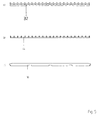
- FIG. 5 shows a sheet metal strip 32 in the upper row a) from the side, in the middle row b) an inner between the two sheet metal strips 32, 33 guide part 44 to be used, in the lower line c) the lower mounting bracket 30 of each supporting sheet metal strip 12.
- the three strips a), b), c) become a uniform sheet metal strip 12 assembled and equipped with needles 24.
Landscapes
- Engineering & Computer Science (AREA)
- Physics & Mathematics (AREA)
- Optics & Photonics (AREA)
- Plasma & Fusion (AREA)
- Mechanical Engineering (AREA)
- Laser Beam Processing (AREA)
Priority Applications (1)
| Application Number | Priority Date | Filing Date | Title |
|---|---|---|---|
| EP01108539A EP1208935A1 (fr) | 2000-11-21 | 2001-04-05 | Support pour une tôle |
Applications Claiming Priority (3)
| Application Number | Priority Date | Filing Date | Title |
|---|---|---|---|
| EP00125473 | 2000-11-21 | ||
| EP00125473 | 2000-11-21 | ||
| EP01108539A EP1208935A1 (fr) | 2000-11-21 | 2001-04-05 | Support pour une tôle |
Publications (1)
| Publication Number | Publication Date |
|---|---|
| EP1208935A1 true EP1208935A1 (fr) | 2002-05-29 |
Family
ID=26071608
Family Applications (1)
| Application Number | Title | Priority Date | Filing Date |
|---|---|---|---|
| EP01108539A Withdrawn EP1208935A1 (fr) | 2000-11-21 | 2001-04-05 | Support pour une tôle |
Country Status (1)
| Country | Link |
|---|---|
| EP (1) | EP1208935A1 (fr) |
Cited By (2)
| Publication number | Priority date | Publication date | Assignee | Title |
|---|---|---|---|---|
| EP1393847A1 (fr) | 2002-08-30 | 2004-03-03 | Trumpf Werkzeugmaschinen GmbH + Co. KG | Support d'une tôle pour une machine à couper thermique et machine et méthode pour la fabrication du support |
| ITVI20100276A1 (it) * | 2010-10-14 | 2012-04-15 | Dalmed Cs S R L | Griglia di supporto per macchine di taglio laser |
Citations (3)
| Publication number | Priority date | Publication date | Assignee | Title |
|---|---|---|---|---|
| JPS6352790A (ja) * | 1986-08-21 | 1988-03-05 | Mitsubishi Electric Corp | レ−ザ加工装置 |
| EP0838314A1 (fr) * | 1996-10-24 | 1998-04-29 | Atom S.p.A. | Dispositif de manipulation et support pour machines de coupe |
| DE19935222A1 (de) * | 1999-07-27 | 2001-02-22 | Meiko Maschb Gmbh & Co | Unterlage für Blech |
-
2001
- 2001-04-05 EP EP01108539A patent/EP1208935A1/fr not_active Withdrawn
Patent Citations (3)
| Publication number | Priority date | Publication date | Assignee | Title |
|---|---|---|---|---|
| JPS6352790A (ja) * | 1986-08-21 | 1988-03-05 | Mitsubishi Electric Corp | レ−ザ加工装置 |
| EP0838314A1 (fr) * | 1996-10-24 | 1998-04-29 | Atom S.p.A. | Dispositif de manipulation et support pour machines de coupe |
| DE19935222A1 (de) * | 1999-07-27 | 2001-02-22 | Meiko Maschb Gmbh & Co | Unterlage für Blech |
Non-Patent Citations (1)
| Title |
|---|
| PATENT ABSTRACTS OF JAPAN vol. 012, no. 269 (M - 723) 27 July 1988 (1988-07-27) * |
Cited By (2)
| Publication number | Priority date | Publication date | Assignee | Title |
|---|---|---|---|---|
| EP1393847A1 (fr) | 2002-08-30 | 2004-03-03 | Trumpf Werkzeugmaschinen GmbH + Co. KG | Support d'une tôle pour une machine à couper thermique et machine et méthode pour la fabrication du support |
| ITVI20100276A1 (it) * | 2010-10-14 | 2012-04-15 | Dalmed Cs S R L | Griglia di supporto per macchine di taglio laser |
Similar Documents
| Publication | Publication Date | Title |
|---|---|---|
| DE10300959B4 (de) | Beschichtereinrichtung für eine Bauvorrichtung zur Erstellung von Formteilen aus Baumaterial | |
| DE4020199C2 (fr) | ||
| DE4212745C2 (de) | Beschneidwerkzeug zum Beschneiden von Ziehteilen am gesamten Umfang und zum gleichzeitigen Querschneiden des abgeschnittenen Abfallstreifens | |
| DE3321062C2 (fr) | ||
| DE2743482A1 (de) | Maschine, insbesondere kombinierte stanz- und schmelzschneidmaschine | |
| DE3920825C2 (de) | Vorrichtung zum Beschneiden und Stumpfschweißen von Band- oder Blechrändern mit einer Lasereinrichtung | |
| EP1208935A1 (fr) | Support pour une tôle | |
| EP0043089A1 (fr) | Auge d'encre pour recevoir de l'encre pour impression | |
| DE19935222C2 (de) | Unterlage für Blech | |
| DE68903625T2 (de) | Einzelschermessermechanismus zum abtrennen von tropfen. | |
| DE29923647U1 (de) | Unterlage für Blech | |
| DE3129820C2 (fr) | ||
| DE102023112767B4 (de) | Tafelschere mit Blechhochhaltevorrichtung | |
| DE3334380A1 (de) | Verfahren und vorrichtung zum schneiden von straengen, insbesondere von duennen metalldraehten | |
| DE1023656B (de) | Blechschere | |
| DE3047538A1 (de) | Vorrichtung und verfahren zum versehen des zahnspitzenbereichs eines saegeblattes mit hartmaterial-zahnschneiden | |
| EP1590521B1 (fr) | Dispositif de coupe servant au decoupage thermique d'une bande textile en mouvement, notamment a motifs | |
| AT382603B (de) | Vorrichtung zum unterteilen eines glasbandes | |
| DE102024116473A1 (de) | Verfahren zum schneiden eines bauteils mittels einer laserschneidvorrichtung sowie laserschneidvorrichtung | |
| DE205258C (fr) | ||
| EP1209102A1 (fr) | Dispositif pour individualiser des barres | |
| CH681085A5 (fr) | ||
| DE2454804C2 (fr) | ||
| DE9006813U1 (de) | Vorrichtung zum Schneiden und zur Zerkleinerung von Pflanzenteilen, besonders zum Beschneiden von Hecken | |
| DE4208073A1 (de) | Verbindungsbruecke zwischen einer bearbeitungsmaschine und einem palettenwechsler |
Legal Events
| Date | Code | Title | Description |
|---|---|---|---|
| PUAI | Public reference made under article 153(3) epc to a published international application that has entered the european phase |
Free format text: ORIGINAL CODE: 0009012 |
|
| AK | Designated contracting states |
Kind code of ref document: A1 Designated state(s): AT BE CH CY DE DK ES FI FR GB GR IE IT LI LU MC NL PT SE TR |
|
| AX | Request for extension of the european patent |
Free format text: AL;LT;LV;MK;RO;SI |
|
| 17P | Request for examination filed |
Effective date: 20021121 |
|
| AKX | Designation fees paid |
Designated state(s): AT BE CH CY DE DK ES FI FR GB GR IE IT LI LU MC NL PT SE TR |
|
| 17Q | First examination report despatched |
Effective date: 20060314 |
|
| STAA | Information on the status of an ep patent application or granted ep patent |
Free format text: STATUS: THE APPLICATION IS DEEMED TO BE WITHDRAWN |
|
| 18D | Application deemed to be withdrawn |
Effective date: 20070724 |