EP1208947B1 - Kraftschrauber - Google Patents
Kraftschrauber Download PDFInfo
- Publication number
- EP1208947B1 EP1208947B1 EP02002313A EP02002313A EP1208947B1 EP 1208947 B1 EP1208947 B1 EP 1208947B1 EP 02002313 A EP02002313 A EP 02002313A EP 02002313 A EP02002313 A EP 02002313A EP 1208947 B1 EP1208947 B1 EP 1208947B1
- Authority
- EP
- European Patent Office
- Prior art keywords
- torque
- nominal
- screw
- drive unit
- angle
- Prior art date
- Legal status (The legal status is an assumption and is not a legal conclusion. Google has not performed a legal analysis and makes no representation as to the accuracy of the status listed.)
- Expired - Lifetime
Links
Images
Classifications
-
- B—PERFORMING OPERATIONS; TRANSPORTING
- B23—MACHINE TOOLS; METAL-WORKING NOT OTHERWISE PROVIDED FOR
- B23P—METAL-WORKING NOT OTHERWISE PROVIDED FOR; COMBINED OPERATIONS; UNIVERSAL MACHINE TOOLS
- B23P19/00—Machines for simply fitting together or separating metal parts or objects, or metal and non-metal parts, whether or not involving some deformation; Tools or devices therefor so far as not provided for in other classes
- B23P19/10—Aligning parts to be fitted together
- B23P19/102—Aligning parts to be fitted together using remote centre compliance devices
-
- B—PERFORMING OPERATIONS; TRANSPORTING
- B23—MACHINE TOOLS; METAL-WORKING NOT OTHERWISE PROVIDED FOR
- B23P—METAL-WORKING NOT OTHERWISE PROVIDED FOR; COMBINED OPERATIONS; UNIVERSAL MACHINE TOOLS
- B23P19/00—Machines for simply fitting together or separating metal parts or objects, or metal and non-metal parts, whether or not involving some deformation; Tools or devices therefor so far as not provided for in other classes
- B23P19/04—Machines for simply fitting together or separating metal parts or objects, or metal and non-metal parts, whether or not involving some deformation; Tools or devices therefor so far as not provided for in other classes for assembling or disassembling parts
- B23P19/06—Screw or nut setting or loosening machines
- B23P19/065—Arrangements for torque limiters or torque indicators in screw or nut setting machines
- B23P19/066—Arrangements for torque limiters or torque indicators in screw or nut setting machines by electrical means
-
- B—PERFORMING OPERATIONS; TRANSPORTING
- B25—HAND TOOLS; PORTABLE POWER-DRIVEN TOOLS; MANIPULATORS
- B25B—TOOLS OR BENCH DEVICES NOT OTHERWISE PROVIDED FOR, FOR FASTENING, CONNECTING, DISENGAGING, OR HOLDING
- B25B23/00—Details of, or accessories for, spanners, wrenches, screwdrivers
- B25B23/14—Arrangement of torque limiters or torque indicators in wrenches or screwdrivers
Definitions
- the invention relates to a power wrench with a drive unit, a scanner for the actual torque and possibly for the actual screw clamping angle and an electronic control of the speed and / or torque and possibly the helical angle.
- German patent 43 07 131 is a power wrench with a drive unit downstream planetary gear, a torque detection on an output shaft, with a transmitter and a shutdown device for the drive unit, a scanning device for detecting the rotational position of the drive unit described, the shutdown an adjustable default device for a specific, determined with the torque detection Includes torque and in addition an adjustable default device for a specific, determined with the rotational position detection overtravel and a shutdown of the drive unit after reaching the set torque and a subsequent further rotation takes place by a set overrun.
- the required torque and a possibly required overrun at the corresponding adjustment elements are set. Then the power screwdriver is plugged onto the screw and moves a support leg against a solid support. After starting the drive unit, the screwing is carried out and the screw tightened, whereby the torque increases.
- the metrologically detected torque value is with by the setting predetermined torque value is compared and if both values agree, an internal switching signal for the tracking control. Based on the currently current rotational position, the drive unit is now rotated further by the set overrun path. After passing through the set trailing path a switching signal for switching off the drive unit and thus to end the screwing is delivered via a shutdown device.
- the operator In the known power wrench, the operator must determine the required setpoint torque based on tables with respect to the screw size and the material quality and enter it into the input electronics. Also, the overtravel must first be determined by the operator to then also be entered into the input electronics. The function of the overrun path and how it is determined is described in the German patent specification 43 07 131 not specified. Also, the metrologically detectable torque value is heavily dependent on external circumstances such as thread friction and the like and not an accurate measure of the actual screw voltage reached.
- a method and a device are described with which a clevis of a universal joint can be screwed onto a thread of a bevel pinion shaft of a differential gear and a lock nut.
- the clevis is screwed onto the bevel pinion shaft and tightened to a predetermined torque, which corresponds to a predetermined preload of the tapered roller bearings of the bevel pinion shaft, while the lock nut is clamped against the clevis with a predetermined tightening torque.
- Both the torque when tightening the clevis and the torque when tightening the lock nut are continuously fed to an evaluation unit, and the speed of the drive motors for the clevis and for the lock nut are continuously reduced with the increase of the torque until the predetermined target torques are reached. At this moment, both drives are switched off and the tightening process is completed.
- the invention is based on the problem to simplify the operation of a power wrench of the type mentioned above and turn off operating errors as possible, without any special requirements are placed on the expertise of the operator.
- it is intended to avoid damage to the bolts to be tightened and to the power wrench, to increase the accuracy with which tightening of the bolts is effected, to reduce or eliminate the effect of the rotational energy of the power unit when turning off the bolt, and to ensure safe transmission of the measuring power. and control signals are ensured.
- a power wrench in which the influence of the rotational energy of the rotating parts on the fferenvorspannkraft is reduced or turned off and a drive unit, an input electrical for inputting a required target biasing force corresponding desired torque, a scanner for the Actual torque, a control and shutdown device for controlling the tightening with a constant, high speed until reaching a predetermined screw torque and then to continuously reducing the speed of the drive unit with decreasing difference between the required target biasing force corresponding desired torque and Having the actual torque and the shutdown of the drive unit in accordance with the actual torque with the required target biasing force corresponding desired torque, wherein the input electronics for inputting the predetermined screw torque, the klei ner than the target torque for clamping a given screw, is set up and from which the speed of the drive unit is reduced.
- the screwing is thus initially carried out at high speed and only after reaching a predetermined torque screw is the reduction of the speed. This results in a shortening of the screwing.
- the speed control according to the invention in conjunction with an input electronics, which is set up for entering the screw size, the thread pitch and the material quality, from which an evaluation determines the target biasing force corresponding desired torque.
- the control and shutdown device for controlling the rotational speed of the drive unit causes the rotational energy of the power wrench when approaching the desired values is always lower and therefore this rotational energy at the moment of switching off is equal to or approximately equal to zero and can not affect the actual biasing force.
- This control of the speed can be used in any power wrench with electronic torque limiter but also in a power wrench in which the control and shutdown device has an electronic fferenspannwinkelbegrenzung.
- Bolt tension angle for further extension of the screw to a value corresponding to the entered data causes.
- the operator therefore no longer needs to use tables to determine the target torque for a particular screw size and thread pitch with a certain material quality and enter the input electronics, but it is sufficient to enter the screw size, thread pitch and material quality directly into the input electronics, whereupon the the resulting desired torque is determined by the transmitter and used to control the power wrench. Incorrect settings, which can lead to damage to the tightening screws and the power wrench are avoided because no special expertise of the operator are required.
- the input electronics for entering the screw size, the material quality, the thread pitch and the clamping length can be configured, the evaluation of a setpoint biasing force, a target torque and ascertain a helical clamping angle, a scanning device ascertains the actual torque and a scanning device determines the actual helical clamping angle, and a control and shut-off device is provided which determines the further rotation of the drive unit if the actual torque matches the setpoint torque and the drive unit is switched off the actual screw clamping angle is effected with the desired screw clamping angle.
- This control device for the power wrench is based on the consideration that the most accurate adjustment of the screw biasing force results from monitoring the SSendehnung, since the screw elongation due to the "Hooke's Law" in a linear relationship to the biasing force, the screw cross section, the clamping length and the elasticity module stands.
- This screw elongation is geometrically directly proportional to the screw clamping angle, but the zero value of the strain can not be determined directly from the screw rotation, since the screw is first with low torque to the fixed system of exciting parts, the joining point, rotated and only then linear increase of the preload force with the screw expansion begins.
- the desired preload force from the entered screw size, the material quality and the clamping length can be determined and determine in conjunction with the entered thread pitch the target torque and the resulting screw clamping angle. It is therefore sufficient first to measure the actual torque to a predetermined height and to let the control and shutdown act on the power wrench, that from this point on the further rotation of the drive unit by a certain angle to the desired target Preload leads, takes place.
- the target torque, from which the further rotation of the drive unit is controlled until reaching the target screw clamping angle, to a value that is smaller than the desired biasing force corresponding torque be set and the further rotation angle of the drive unit until reaching the the target biasing force corresponding desired screw clamping angle determined from the difference between the desired screw clamping angle and the setpoint torque corresponding screw clamping angle and is used to switch off the drive unit.
- the target torque is set to 10% to 20% of the torque corresponding to the target biasing force, and the further rotational angle amounts to 90% to 80% of the target bolt clamping angle corresponding to the target biasing force.
- the transmitter are integrated into the drive unit, while the input electronics and possibly the transmitter are designed as independent control unit and the control and Deployment device or on the evaluation cable-free with bidirectional or unidirectional transfer of data act.
- the remote transmission can be configured as uni- or bidirectional infrared link and a corresponding infrared signal receiver can be arranged on the drive unit.
- control and shutdown device when the control and shutdown device is integrated into the drive unit, while the input electronics and the transmitter are designed as independent controller, they can be combined in a portable computer having a bidirectional IrDA interface with infrared transmission, while a corresponding interface to the Drive unit is arranged.
- Unidirectional infrared communication devices are known as infrared remote control for television sets. They enable unidirectional data transmission over distances up to 36 m under optimal conditions. In these unidirectional infrared data transmission systems, the quiescent current of the transmitter is almost zero, while the current during transmission is only a few milliamperes. The receiver also has only a current consumption of a few milliamperes, i. H. in a range acceptable for the power supplies common to portable power screwdrivers.
- IrDA interface This is a standardized, bidirectional interface with infrared transmission.
- a corresponding interface is located on the power wrench and these IrDA modules have a low power consumption of a few microamps at rest and some milliamps in the active state.
- the input electronics has a display, it can be set up so that the entered values, the calculated target values, and / or the current actual torque run and / or the current actual SSencryptwinkelverlauf are displayed on the display.
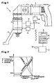
- a power wrench generally designated by the reference numeral 1, has a drive unit 2, which is shown here as an electric drive unit, but which may also be operated pneumatically or hydraulically.
- a planetary gear 3 is attached, which, as shown, may have an angle drive, which, however, may extend coaxially to the main axis of rotation of the drive unit.
- the planetary gear 3 serves to reduce the rotational speed of the drive unit 2 and to increase the achievable torque.
- a support leg 4 is rotatably disposed, which moves when tightening a screw against a solid support and receives in this way the reaction torque.
- the square 5 is used to attach a Moscownuß.
- To the drive unit 2 includes an input electronics 6, which has a keyboard 7 and possibly a display 8 for displaying the inputs.
- this input electronics 6 the screw size, the material quality, the thread pitch, enter the clamping length and also display on the display 8. These values are forwarded to an evaluation 9, which from the entered screw size and the material quality a target torque or from the screw size, the material grade and the clamping length a target biasing force and from this including the thread pitch a resulting target torque and finally from the Target preload and the thread pitch determined a resulting bolt clamping angle.
- These determined desired values and / or the current actual torque curve and / or the current actual screw rotational angle course can also be displayed on the display 8.
- These scanning devices 10, 11 may be conventional, non-contact scanning devices, as z. B. in the German patent 43 07 131 are described act.
- the measured values of the scanning device 10, 11 are passed to a control and shutdown device 12, which acts on the drive unit 2.
- the scanning devices 10, 11 and the control and shutdown device 12 and possibly the evaluation 9 are integrated into the drive unit 2, while the input electronics 6 and possibly the transmitter 9 are formed independently of the power wrench 1 as a control unit and the power wrench. 1 can be connected via a cable, or particularly preferably wirelessly with remote transmission of the data acts on the integrated into the power wrench 1 electronics. If an infrared remote transmission is used for this purpose, the data entered into the input electronics 6 or the control data converted in the evaluation unit 9 can be transmitted to the power wrench 1 in a cable-free manner. If the input electronics 6 and the transmitter 9 are combined to form a portable computer and this with a so-called.
- IrDA interface 13 as Remote transmission is provided, the infrared signals can be transmitted from this interface to a corresponding interface 14 on the power wrench 1, which is in communication with the control and shutdown device 12.
- This IrDA interface 13 and the corresponding interface 14 are designed as standardized bidirectional interfaces with infrared transmission for distances up to one meter and transmission rates of more than 1 Mbit / s.
- These IrDA modules 13, 14 have at rest a low power consumption of a few microamps and in the active state of a few milliamperes, which is within a range that is allowed for the usual in portable power screw power supplies.
- the principle-based, optimal galvanic isolation of the input electronics 6 and the transmitter 9 from the power screwdriver 1 and the low cost through the use of standard components. These standard components have such small dimensions that they can be easily integrated into the housing of the power wrench 1.
- the power wrench 1 only work with a torque limitation, only the screw size and the material quality needs to be entered into the input electronics 6, so that the transmitter 9 determines the corresponding desired torque.
- the scanner 10 measures the actual torque, and the control and shutdown 12 switches off the drive unit 2 in accordance with the actual torque with the target torque.
- a high-precision tightening of the screw to a desired preload force which can be determined from the screw size, the material quality and the clamping length to which the screw expansion is proportional to the input electronics 6, the screw size, the material grade, the thread pitch and the clamping length entered, from which the evaluation 9 determines a target biasing force, a target torque and a target screw clamping angle.
- the actual torque is determined by means of the scanning device 10 and the actual screw clamping angle is determined by means of the scanning device 11 and fed to the control and shut-off device 12.
- the control and shutdown device 12 is arranged so that it causes the further rotation of the drive unit by a certain angle in accordance with the actual torque with the target torque and the drive unit 2 shuts off when the actual screw clamping angle coincides with the desired clamping angle.
- This target torque from which the further rotation of the drive unit 2 is controlled until the desired screw clamping angle is reached, is smaller than the desired preload corresponding torque, preferably it corresponds to 10% to 20% of the desired preload force corresponding torque, while Then the further rotation angle amounts to 90% to 80% of the target preload corresponding target screw tension angle.
- the torque M initially remains at a low value during rotation of the screw until reaching the joining point and increases linearly with the helical clamping angle only after exceeding 10% to 20% of the torque corresponding to the desired preload force.
- the starting point for the further rotation angle ⁇ is 10% to 20% of the torque corresponding to the desired preload force and this further rotation angle ⁇ is correspondingly 20% to 80% of the desired preloading force corresponding desired screw clamping angle, which can be monitored very accurately.
- the speed n of the drive unit 2 can be controlled according to the invention so that it steadily decreases with decreasing difference between the target torque and the actual torque or between the target screw clamping angle and the actual screw clamping angle and upon reaching the desired torque or the set screw tension angle goes to zero, ie that the drive unit is switched off.
- This reduction in the rotational speed of the drive unit 2 can, as shown, be linear, but also a non-linear course is adjustable. In particular, it is possible initially to carry out the screwing operation at high speed and to reduce the speed only after reaching a predeterminable screwing torque. This results in a shortening of the screwing.
- This speed control is in Fig. 2 shown in dashed lines.
- the scanning device 10 for the actual torque so that it measures the actual torque of an already tightened screw by slightly further rotation and the transmitter 9 therefrom a target torque and / or causes a target screw clamping angle for further tightening the screw to a value corresponding to the input data.
Landscapes
- Engineering & Computer Science (AREA)
- Mechanical Engineering (AREA)
- Details Of Spanners, Wrenches, And Screw Drivers And Accessories (AREA)
Applications Claiming Priority (3)
| Application Number | Priority Date | Filing Date | Title |
|---|---|---|---|
| DE19647813A DE19647813C2 (de) | 1996-11-19 | 1996-11-19 | Kraftschrauber |
| DE19647813 | 1996-11-19 | ||
| EP97945877A EP0946336B1 (de) | 1996-11-19 | 1997-10-29 | Kraftschrauber |
Related Parent Applications (1)
| Application Number | Title | Priority Date | Filing Date |
|---|---|---|---|
| EP97945877A Division EP0946336B1 (de) | 1996-11-19 | 1997-10-29 | Kraftschrauber |
Publications (3)
| Publication Number | Publication Date |
|---|---|
| EP1208947A2 EP1208947A2 (de) | 2002-05-29 |
| EP1208947A3 EP1208947A3 (de) | 2004-06-09 |
| EP1208947B1 true EP1208947B1 (de) | 2008-09-10 |
Family
ID=7812110
Family Applications (2)
| Application Number | Title | Priority Date | Filing Date |
|---|---|---|---|
| EP02002313A Expired - Lifetime EP1208947B1 (de) | 1996-11-19 | 1997-10-29 | Kraftschrauber |
| EP97945877A Expired - Lifetime EP0946336B1 (de) | 1996-11-19 | 1997-10-29 | Kraftschrauber |
Family Applications After (1)
| Application Number | Title | Priority Date | Filing Date |
|---|---|---|---|
| EP97945877A Expired - Lifetime EP0946336B1 (de) | 1996-11-19 | 1997-10-29 | Kraftschrauber |
Country Status (5)
| Country | Link |
|---|---|
| US (1) | US6161629A (da) |
| EP (2) | EP1208947B1 (da) |
| DE (3) | DE19647813C2 (da) |
| DK (2) | DK0946336T3 (da) |
| WO (1) | WO1998022263A1 (da) |
Families Citing this family (71)
| Publication number | Priority date | Publication date | Assignee | Title |
|---|---|---|---|---|
| FR2779375B1 (fr) * | 1998-06-09 | 2000-08-18 | Leblanc Ets | Dispositif pour le vissage a serrage controle |
| JP3906606B2 (ja) * | 1999-06-11 | 2007-04-18 | 松下電工株式会社 | インパクト回転工具 |
| SE514921C2 (sv) * | 1999-06-22 | 2001-05-21 | Atlas Copco Tools Ab | Metod för bestämning av optimala värden för skruvåtdragningsparametrar genom driftssimulering |
| ITMI991523A1 (it) * | 1999-07-12 | 2001-01-12 | Blm S A S Di L Bareggi & C | Utensile di serraggio e stazione di monitoraggio con comunicazione reciproca senza fili |
| JP3798229B2 (ja) * | 2000-04-12 | 2006-07-19 | 株式会社マキタ | 電動工具 |
| EP1982798A3 (en) | 2000-03-16 | 2008-11-12 | Makita Corporation | Power tool |
| DE10045985A1 (de) * | 2000-09-16 | 2002-03-28 | Hilti Ag | Elektrohandwerkzeuggerät mt Drehmomentkontrolle |
| AU2001292176A1 (en) * | 2000-10-11 | 2002-04-22 | Ingersoll-Rand Company | Electronically controlled torque management system for threaded fastening |
| WO2002085568A1 (de) * | 2001-04-20 | 2002-10-31 | Paul-Heinz Wagner | Drehschrauber |
| DE10127821C5 (de) * | 2001-06-07 | 2005-05-12 | Tool Express-Service Schraubertechnik Gmbh | Anordnung zum Betrieb eines Elektro-Schraubers |
| US6668212B2 (en) | 2001-06-18 | 2003-12-23 | Ingersoll-Rand Company | Method for improving torque accuracy of a discrete energy tool |
| US6516896B1 (en) | 2001-07-30 | 2003-02-11 | The Stanley Works | Torque-applying tool and control therefor |
| CN100595001C (zh) * | 2002-01-21 | 2010-03-24 | Ms仪器制造有限公司 | 安装工具及其头盖以及用于检验安装过程的方法 |
| AU2002340948A1 (en) * | 2002-01-21 | 2003-07-30 | Ms Verwaltungs- Und Patentgesellschaft Mbh | Setting tool comprising a device for measuring tensile stress |
| EP1992429A1 (de) * | 2002-01-21 | 2008-11-19 | MS Gerätebau GmbH | Setzwerkzeug mit Mitteln zur Kontrolle von Setzvorgängen |
| DE10248298A1 (de) * | 2002-01-21 | 2003-07-31 | Ms Verwaltungs Und Patentgmbh | Setzwerk mit Mitteln zur Kontrolle von Setzvorgängen |
| FR2852879B1 (fr) | 2003-03-26 | 2007-04-06 | Snecma Moteurs | Cle a serrage controle |
| US7162320B2 (en) * | 2003-03-31 | 2007-01-09 | Honda Motor Co., Ltd. | Assembly line quality control |
| DE10334244A1 (de) * | 2003-07-28 | 2005-02-17 | Robert Bosch Gmbh | Schraubwerkzeug für winkelgetreues Einschrauben, sowie Verfahren hierfür |
| JP2005118910A (ja) * | 2003-10-14 | 2005-05-12 | Matsushita Electric Works Ltd | インパクト回転工具 |
| JP4906236B2 (ja) * | 2004-03-12 | 2012-03-28 | 株式会社マキタ | 締付工具 |
| US7552781B2 (en) | 2004-10-20 | 2009-06-30 | Black & Decker Inc. | Power tool anti-kickback system with rotational rate sensor |
| US20060157262A1 (en) * | 2005-01-14 | 2006-07-20 | Jui-Yu Chen | Power tool having presetable digital control of torque output |
| US20070227310A1 (en) * | 2006-03-31 | 2007-10-04 | Heiko Roehm | Hand power tool |
| DE102007019408B3 (de) * | 2007-04-23 | 2008-11-27 | Lösomat Schraubtechnik Neef Gmbh | Kraftschrauber |
| DE102007019409B3 (de) * | 2007-04-23 | 2008-11-13 | Lösomat Schraubtechnik Neef Gmbh | Kraftschrauber |
| DE102007036328A1 (de) * | 2007-07-31 | 2009-02-05 | Lösomat Schraubtechnik Neef Gmbh | Mobiles Kraftschrauber-Bediengerät |
| GB2451489B (en) | 2007-08-02 | 2009-07-29 | Peter Dean Christmas | Drum tuning device |
| SE531646C2 (sv) * | 2007-10-17 | 2009-06-16 | Atlas Copco Tools Ab | Skruvdragare med organ för övervakning av en reaktionsarm |
| FR2929162B1 (fr) * | 2008-03-26 | 2010-05-21 | Peugeot Citroen Automobiles Sa | Douille de visseuse electrique asservie et systeme de vissage associe |
| EP2147750A1 (de) * | 2008-07-24 | 2010-01-27 | Alexander Kipfelsberger | Vorrichtung mit einem Schraubwerkzeug mit elektronischer Drehmomentbegrenzung und Verfahren zum Betrieb der Vorrichtung |
| US8418778B2 (en) | 2010-01-07 | 2013-04-16 | Black & Decker Inc. | Power screwdriver having rotary input control |
| CN102753782B (zh) * | 2010-01-07 | 2015-09-30 | 布莱克和戴克公司 | 具有旋转输入控制的电动螺丝起子 |
| US9475180B2 (en) | 2010-01-07 | 2016-10-25 | Black & Decker Inc. | Power tool having rotary input control |
| US9266178B2 (en) | 2010-01-07 | 2016-02-23 | Black & Decker Inc. | Power tool having rotary input control |
| DE102010044823B4 (de) | 2010-09-09 | 2024-02-29 | Robert Bosch Gmbh | Schraubspindel |
| US8996142B2 (en) * | 2010-12-22 | 2015-03-31 | Aktiebolaget Skf | Alignment software process management |
| FR2972665B1 (fr) * | 2011-03-18 | 2014-05-30 | Renault Georges Ets | Procede pour adapter automatiquement la vitesse de vissage d’un outil de vissage pour atteindre un couple de consigne par freinage anticipe. |
| DE102011112536B3 (de) * | 2011-09-05 | 2012-12-13 | Audi Ag | Werkzeug und Verfahren zum Verbinden eines elektrischen Pols einer Batteriezelle mit einem elektrischen Leiter |
| EP2631035B1 (en) | 2012-02-24 | 2019-10-16 | Black & Decker Inc. | Power tool |
| DE102012204009B4 (de) * | 2012-03-14 | 2014-12-11 | Mtu Friedrichshafen Gmbh | Verfahren zur Montage eines Montageteils in eine Aufnahme in einer bestimmten Schraubstellung, Brennkraftmaschine mit einem in einer bestimmten Schraubstellung gesicherten Montageteil in einer Aufnahme |
| US20140110138A1 (en) * | 2012-10-23 | 2014-04-24 | David Zarrin | Protective apparatus in connection with machine tools to safeguard workload installation |
| US10131042B2 (en) | 2013-10-21 | 2018-11-20 | Milwaukee Electric Tool Corporation | Adapter for power tool devices |
| DE102015000555A1 (de) * | 2015-01-20 | 2016-07-21 | Frank Hohmann | Drehschrauber |
| US9839998B2 (en) * | 2015-04-07 | 2017-12-12 | General Electric Company | Control system and apparatus for power wrench |
| KR200490007Y1 (ko) | 2015-04-28 | 2019-11-04 | 밀워키 일렉트릭 툴 코포레이션 | 정밀 토크 스크류드라이버 |
| US10357871B2 (en) | 2015-04-28 | 2019-07-23 | Milwaukee Electric Tool Corporation | Precision torque screwdriver |
| CN110213676B (zh) | 2015-05-04 | 2022-08-19 | 米沃奇电动工具公司 | 电动工具和无线通信方法 |
| US10603770B2 (en) | 2015-05-04 | 2020-03-31 | Milwaukee Electric Tool Corporation | Adaptive impact blow detection |
| US10295990B2 (en) | 2015-05-18 | 2019-05-21 | Milwaukee Electric Tool Corporation | User interface for tool configuration and data capture |
| CN107921613B (zh) | 2015-06-02 | 2020-11-06 | 米沃奇电动工具公司 | 具有电子离合器的多速电动工具 |
| WO2016205404A1 (en) | 2015-06-15 | 2016-12-22 | Milwaukee Electric Tool Corporation | Hydraulic crimper tool |
| WO2016203315A2 (en) | 2015-06-15 | 2016-12-22 | Milwaukee Electric Tool Corporation | Power tool communication system |
| US10380883B2 (en) | 2015-06-16 | 2019-08-13 | Milwaukee Electric Tool Corporation | Power tool profile sharing and permissions |
| DE102015115469B4 (de) | 2015-09-14 | 2024-04-11 | Frank Hohmann | Werkzeugsystem mit Kraftschrauber und externem Bedienteil |
| US10345797B2 (en) | 2015-09-18 | 2019-07-09 | Milwaukee Electric Tool Corporation | Power tool operation recording and playback |
| PL3369292T3 (pl) | 2015-10-30 | 2021-04-06 | Milwaukee Electric Tool Corporation | Zdalne sterowanie, konfiguracja i monitorowanie oświetlenia |
| US11424601B2 (en) | 2015-11-02 | 2022-08-23 | Milwaukee Electric Tool Corporation | Externally configurable worksite power distribution box |
| EP3202537B1 (en) | 2015-12-17 | 2019-06-05 | Milwaukee Electric Tool Corporation | System and method for configuring a power tool with an impact mechanism |
| JP7189018B2 (ja) | 2016-01-05 | 2022-12-13 | ミルウォーキー エレクトリック ツール コーポレーション | 動力工具のための振動低減システム及び方法 |
| EP3411204B1 (en) | 2016-02-03 | 2021-07-28 | Milwaukee Electric Tool Corporation | System and methods for configuring a reciprocating saw |
| TWM552413U (zh) | 2016-02-25 | 2017-12-01 | 米沃奇電子工具公司 | 包括輸出位置感測器之動力工具 |
| US11622392B2 (en) | 2016-06-06 | 2023-04-04 | Milwaukee Electric Tool Corporation | System and method for establishing a wireless connection between power tool and mobile device |
| TWM555274U (zh) | 2016-06-06 | 2018-02-11 | 米沃奇電子工具公司 | 用以與動力工具裝置作連接的行動裝置 |
| US10589413B2 (en) | 2016-06-20 | 2020-03-17 | Black & Decker Inc. | Power tool with anti-kickback control system |
| DE102017008859B3 (de) | 2017-09-21 | 2018-11-29 | Alki Technik Gmbh Schraubsysteme Entwicklung-Produktion-Vertrieb | Kalibrierverfahren für einen Kraftschrauber |
| US11752604B2 (en) | 2018-04-13 | 2023-09-12 | Snap-On Incorporated | System and method for measuring torque and angle |
| GB2594945A (en) * | 2020-05-12 | 2021-11-17 | Black & Decker Inc | A power tool |
| JP7592844B2 (ja) | 2020-08-10 | 2024-12-02 | ミルウォーキー エレクトリック ツール コーポレイション | クラッチ設定センサを備える電動ドライバ |
| DE102020215506A1 (de) | 2020-12-09 | 2022-06-09 | Robert Bosch Gesellschaft mit beschränkter Haftung | Sensormodul für eine Handwerkzeugmaschine |
| DE102022113988A1 (de) | 2022-06-02 | 2023-12-07 | Bayerische Motoren Werke Aktiengesellschaft | Verfahren zur Ermittlung einer wenigstens einen Betriebsparameter eines Schraubwerkzeugs im Rahmen eines Schraubprozesses steuernden Arbeitsregel |
Family Cites Families (19)
| Publication number | Priority date | Publication date | Assignee | Title |
|---|---|---|---|---|
| DE2918845A1 (de) * | 1979-05-10 | 1980-11-20 | Licentia Gmbh | Verfahren zum anschrauben eines halbleiter-bauteils an ein kuehlblech und schrauber fuer das verfahren |
| US4375121A (en) * | 1980-04-07 | 1983-03-01 | Sps Technologies | Dynamic friction indicator and tightening system usable therewith |
| JPS57121477A (en) * | 1981-01-16 | 1982-07-28 | Matsushita Electric Industrial Co Ltd | Fixed torque screw clamping device |
| DE3318910A1 (de) * | 1983-05-25 | 1984-11-29 | Oskar Ing.(grad.) 7073 Lorch Mohilo | Verfahren und einrichtung zum programmieren eines elektronischen schraubenschluessels |
| DE3327964A1 (de) * | 1983-08-03 | 1985-02-28 | Oskar Ing.(grad.) 7073 Lorch Mohilo | Verfahren zum identifizieren von verbindungsschrauben nach typ und/oder anziehvorschrift |
| DE3422522A1 (de) * | 1984-06-16 | 1985-12-19 | Deutsche Gardner-Denver GmbH, 7084 Westhausen | Streckgrenzgesteuertes anziehverfahren fuer verschraubungen |
| SE8802566L (sv) * | 1988-07-08 | 1990-01-09 | Atlas Copco Tools Ab | Motordrivet verktyg och drivsystem foer detta |
| US5154242A (en) * | 1990-08-28 | 1992-10-13 | Matsushita Electric Works, Ltd. | Power tools with multi-stage tightening torque control |
| JPH04164578A (ja) * | 1990-10-26 | 1992-06-10 | Matsushita Electric Works Ltd | 充電工具 |
| JP2943457B2 (ja) * | 1991-09-30 | 1999-08-30 | トヨタ自動車株式会社 | ナットランナ |
| JPH06170662A (ja) * | 1992-01-28 | 1994-06-21 | Nitto Seiko Co Ltd | 自動ねじ締め機 |
| US5315501A (en) * | 1992-04-03 | 1994-05-24 | The Stanley Works | Power tool compensator for torque overshoot |
| US5170852A (en) * | 1992-05-11 | 1992-12-15 | Nitto Seiko Co., Ltd. | Automatic screw fastening machine |
| US5215270A (en) * | 1992-06-18 | 1993-06-01 | Cooper Industries, Inc. | Method for tightening a fastener |
| GB2273574B (en) * | 1992-12-21 | 1995-11-29 | Daimler Benz Ag | Process and a device for the rotation-angle-monitored tightening or loosening of screw connections |
| DE4307131C2 (de) * | 1993-03-06 | 1995-11-16 | Albert Kipfelsberger | Kraftschrauber mit elektronischer Drehmomentbegrenzung |
| JP3000185B2 (ja) * | 1993-04-21 | 2000-01-17 | 株式会社山崎歯車製作所 | インパクトレンチによるボルト締結方法 |
| DE4316331A1 (de) * | 1993-05-15 | 1994-11-17 | Tilo Heinzmann | Elektroschrauber mit voreinstellbaren Drehmomenten und Drehzahlen |
| DE4404419C2 (de) * | 1994-02-11 | 1997-06-05 | Schatz Gmbh | Verfahren und Vorrichtung zum gesteuerten Festziehen von Schraubverbindungen |
-
1996
- 1996-11-19 DE DE19647813A patent/DE19647813C2/de not_active Expired - Lifetime
-
1997
- 1997-10-29 DE DE59707303T patent/DE59707303D1/de not_active Expired - Lifetime
- 1997-10-29 DE DE59712965T patent/DE59712965D1/de not_active Expired - Lifetime
- 1997-10-29 DK DK97945877T patent/DK0946336T3/da active
- 1997-10-29 US US09/308,545 patent/US6161629A/en not_active Expired - Lifetime
- 1997-10-29 EP EP02002313A patent/EP1208947B1/de not_active Expired - Lifetime
- 1997-10-29 EP EP97945877A patent/EP0946336B1/de not_active Expired - Lifetime
- 1997-10-29 WO PCT/EP1997/005974 patent/WO1998022263A1/de not_active Ceased
- 1997-10-29 DK DK02002313T patent/DK1208947T3/da active
Also Published As
| Publication number | Publication date |
|---|---|
| EP1208947A3 (de) | 2004-06-09 |
| DK0946336T3 (da) | 2002-09-09 |
| EP0946336B1 (de) | 2002-05-15 |
| WO1998022263A1 (de) | 1998-05-28 |
| DK1208947T3 (da) | 2009-01-05 |
| EP1208947A2 (de) | 2002-05-29 |
| DE19647813A1 (de) | 1998-06-04 |
| EP0946336A1 (de) | 1999-10-06 |
| DE59707303D1 (de) | 2002-06-20 |
| DE59712965D1 (de) | 2008-10-23 |
| US6161629A (en) | 2000-12-19 |
| DE19647813C2 (de) | 2003-07-03 |
Similar Documents
| Publication | Publication Date | Title |
|---|---|---|
| EP1208947B1 (de) | Kraftschrauber | |
| EP2067576A2 (de) | Schraubwerkzeug und Verfahren zur Steuerung des Anzugswinkels von Verschraubungen | |
| DE69022030T2 (de) | Einrichtung zum steuern eines motors für das zusammenfügen oder lösen von zwei elementen. | |
| EP0653259B1 (de) | Verfahren zum Setzen von Blindnieten und Blindnietmuttern und Setzgerät für Blindniete und Blindnietmuttern | |
| EP0730330B1 (de) | Antriebsvorrichtung für Schliessteile bei Kraftfahrzeugen | |
| EP3408451B1 (de) | Schraubmaschine | |
| DE2718429A1 (de) | Verfahren und vorrichtung zum herstellen einer schraubverbindung bestimmter spannung | |
| EP3571017B1 (de) | Verfahren und vorrichtung zum anziehen von verschraubungen | |
| EP0070354B1 (de) | Vorrichtung zur rückwirkungsfreien Mischwerteinstellung bei Hubwerken von Landmaschinen | |
| DE112016001615T5 (de) | Servolenkungsvorrichtung und Steuergerät für Vorrichtung im Fahrzeug | |
| DE4208426B4 (de) | Verfahren zum Steuern von Torantrieben und Vorrichtung hierfür | |
| EP0721695A1 (de) | Elektromotor mit mitteln zur erfassung des drehmomentes | |
| DE4024577A1 (de) | Verfahren zur steuerung einer vorspannkraft in einer schraubenverbindung | |
| DE10133923A1 (de) | Verfahren zur automatischen Steuerung eines Schraubvorgangs | |
| DE102015103903B4 (de) | Kraftschrauber mit direkter Drehwinkel- und/oder Drehmomentmessung | |
| DE3222156A1 (de) | Schrauber zum definierten anziehen von schrauben mittels eines hilfskraftbetriebenen werkzeugs | |
| DE102017223589A1 (de) | Verfahren zur Montage einer Schraube, Montagevorrichtung sowie Steuerungsvorrichtung | |
| DE19736547C2 (de) | Verfahren zur Erzeugung eines definierten Verspannmoments für Schraubverbindungen | |
| WO2006048420A1 (de) | Verfahren zur steuerung eines anzugverhaltens einer schraubeinrichtung | |
| DE102017212711B4 (de) | Spannvorrichtung mit Kraftmesseinrichtung zum Verspannen eines Werkstücks und Verwendung dieser Spannvorrichtung | |
| EP3093107B1 (de) | Schraubeinheit sowie verfahren zum einschrauben einer schraube in ein werkstück | |
| EP0786848B1 (de) | Elektronische Überwachung der Antriebskraft eines Antriebs | |
| DE4235954C2 (de) | Verfahren und Vorrichtung zum Messen des Spannwinkels bei einem elektronischen Drehmomentschlüssel | |
| DE3216773A1 (de) | Vorrichtung zum anziehen eines ein gewinde tragenden verbindungselements mit begrenzung des endanzugsdrehmoments | |
| DE202004020322U1 (de) | Druckmittelbetriebener Kraftschrauber |
Legal Events
| Date | Code | Title | Description |
|---|---|---|---|
| PUAI | Public reference made under article 153(3) epc to a published international application that has entered the european phase |
Free format text: ORIGINAL CODE: 0009012 |
|
| 17P | Request for examination filed |
Effective date: 20020223 |
|
| AC | Divisional application: reference to earlier application |
Ref document number: 946336 Country of ref document: EP |
|
| AK | Designated contracting states |
Kind code of ref document: A2 Designated state(s): DE DK FR IT NL |
|
| PUAL | Search report despatched |
Free format text: ORIGINAL CODE: 0009013 |
|
| AK | Designated contracting states |
Kind code of ref document: A3 Designated state(s): DE DK FR IT NL |
|
| RIC1 | Information provided on ipc code assigned before grant |
Ipc: 7B 25B 23/14 A Ipc: 7B 23P 19/06 B |
|
| AKX | Designation fees paid |
Designated state(s): DE DK FR IT NL |
|
| 17Q | First examination report despatched |
Effective date: 20061005 |
|
| 17Q | First examination report despatched |
Effective date: 20061005 |
|
| GRAP | Despatch of communication of intention to grant a patent |
Free format text: ORIGINAL CODE: EPIDOSNIGR1 |
|
| GRAC | Information related to communication of intention to grant a patent modified |
Free format text: ORIGINAL CODE: EPIDOSCIGR1 |
|
| GRAS | Grant fee paid |
Free format text: ORIGINAL CODE: EPIDOSNIGR3 |
|
| GRAA | (expected) grant |
Free format text: ORIGINAL CODE: 0009210 |
|
| AC | Divisional application: reference to earlier application |
Ref document number: 0946336 Country of ref document: EP Kind code of ref document: P |
|
| AK | Designated contracting states |
Kind code of ref document: B1 Designated state(s): DE DK FR IT NL |
|
| REF | Corresponds to: |
Ref document number: 59712965 Country of ref document: DE Date of ref document: 20081023 Kind code of ref document: P |
|
| REG | Reference to a national code |
Ref country code: DK Ref legal event code: T3 |
|
| PLBE | No opposition filed within time limit |
Free format text: ORIGINAL CODE: 0009261 |
|
| STAA | Information on the status of an ep patent application or granted ep patent |
Free format text: STATUS: NO OPPOSITION FILED WITHIN TIME LIMIT |
|
| 26N | No opposition filed |
Effective date: 20090611 |
|
| REG | Reference to a national code |
Ref country code: DE Ref legal event code: R082 Ref document number: 59712965 Country of ref document: DE Representative=s name: BUNGARTZ CHRISTOPHERSEN PARTNERSCHAFT MBB PATE, DE |
|
| REG | Reference to a national code |
Ref country code: FR Ref legal event code: PLFP Year of fee payment: 19 |
|
| REG | Reference to a national code |
Ref country code: FR Ref legal event code: PLFP Year of fee payment: 20 |
|
| PGFP | Annual fee paid to national office [announced via postgrant information from national office to epo] |
Ref country code: NL Payment date: 20161019 Year of fee payment: 20 Ref country code: FR Payment date: 20161020 Year of fee payment: 20 Ref country code: DE Payment date: 20161020 Year of fee payment: 20 Ref country code: DK Payment date: 20161019 Year of fee payment: 20 |
|
| PGFP | Annual fee paid to national office [announced via postgrant information from national office to epo] |
Ref country code: IT Payment date: 20161024 Year of fee payment: 20 |
|
| REG | Reference to a national code |
Ref country code: DE Ref legal event code: R071 Ref document number: 59712965 Country of ref document: DE |
|
| REG | Reference to a national code |
Ref country code: DK Ref legal event code: EUP Effective date: 20171029 |
|
| REG | Reference to a national code |
Ref country code: NL Ref legal event code: MK Effective date: 20171028 |