EP1208996A2 - Appareil pour la production de blanchets d'impression tubulaires - Google Patents
Appareil pour la production de blanchets d'impression tubulaires Download PDFInfo
- Publication number
- EP1208996A2 EP1208996A2 EP01126529A EP01126529A EP1208996A2 EP 1208996 A2 EP1208996 A2 EP 1208996A2 EP 01126529 A EP01126529 A EP 01126529A EP 01126529 A EP01126529 A EP 01126529A EP 1208996 A2 EP1208996 A2 EP 1208996A2
- Authority
- EP
- European Patent Office
- Prior art keywords
- layer
- sleeve
- printing blanket
- compressible
- urethane
- Prior art date
- Legal status (The legal status is an assumption and is not a legal conclusion. Google has not performed a legal analysis and makes no representation as to the accuracy of the status listed.)
- Granted
Links
Images


Classifications
-
- B—PERFORMING OPERATIONS; TRANSPORTING
- B41—PRINTING; LINING MACHINES; TYPEWRITERS; STAMPS
- B41N—PRINTING PLATES OR FOILS; MATERIALS FOR SURFACES USED IN PRINTING MACHINES FOR PRINTING, INKING, DAMPING, OR THE LIKE; PREPARING SUCH SURFACES FOR USE AND CONSERVING THEM
- B41N10/00—Blankets or like coverings; Coverings for wipers for intaglio printing
- B41N10/02—Blanket structure
-
- B—PERFORMING OPERATIONS; TRANSPORTING
- B41—PRINTING; LINING MACHINES; TYPEWRITERS; STAMPS
- B41N—PRINTING PLATES OR FOILS; MATERIALS FOR SURFACES USED IN PRINTING MACHINES FOR PRINTING, INKING, DAMPING, OR THE LIKE; PREPARING SUCH SURFACES FOR USE AND CONSERVING THEM
- B41N2207/00—Location or type of the layers in shells for rollers of printing machines
- B41N2207/04—Intermediate layers
-
- B—PERFORMING OPERATIONS; TRANSPORTING
- B41—PRINTING; LINING MACHINES; TYPEWRITERS; STAMPS
- B41N—PRINTING PLATES OR FOILS; MATERIALS FOR SURFACES USED IN PRINTING MACHINES FOR PRINTING, INKING, DAMPING, OR THE LIKE; PREPARING SUCH SURFACES FOR USE AND CONSERVING THEM
- B41N2210/00—Location or type of the layers in multi-layer blankets or like coverings
- B41N2210/02—Top layers
-
- B—PERFORMING OPERATIONS; TRANSPORTING
- B41—PRINTING; LINING MACHINES; TYPEWRITERS; STAMPS
- B41N—PRINTING PLATES OR FOILS; MATERIALS FOR SURFACES USED IN PRINTING MACHINES FOR PRINTING, INKING, DAMPING, OR THE LIKE; PREPARING SUCH SURFACES FOR USE AND CONSERVING THEM
- B41N2210/00—Location or type of the layers in multi-layer blankets or like coverings
- B41N2210/04—Intermediate layers
-
- B—PERFORMING OPERATIONS; TRANSPORTING
- B41—PRINTING; LINING MACHINES; TYPEWRITERS; STAMPS
- B41N—PRINTING PLATES OR FOILS; MATERIALS FOR SURFACES USED IN PRINTING MACHINES FOR PRINTING, INKING, DAMPING, OR THE LIKE; PREPARING SUCH SURFACES FOR USE AND CONSERVING THEM
- B41N2210/00—Location or type of the layers in multi-layer blankets or like coverings
- B41N2210/14—Location or type of the layers in multi-layer blankets or like coverings characterised by macromolecular organic compounds
-
- Y—GENERAL TAGGING OF NEW TECHNOLOGICAL DEVELOPMENTS; GENERAL TAGGING OF CROSS-SECTIONAL TECHNOLOGIES SPANNING OVER SEVERAL SECTIONS OF THE IPC; TECHNICAL SUBJECTS COVERED BY FORMER USPC CROSS-REFERENCE ART COLLECTIONS [XRACs] AND DIGESTS
- Y10—TECHNICAL SUBJECTS COVERED BY FORMER USPC
- Y10S—TECHNICAL SUBJECTS COVERED BY FORMER USPC CROSS-REFERENCE ART COLLECTIONS [XRACs] AND DIGESTS
- Y10S428/00—Stock material or miscellaneous articles
- Y10S428/909—Resilient layer, e.g. printer's blanket
-
- Y—GENERAL TAGGING OF NEW TECHNOLOGICAL DEVELOPMENTS; GENERAL TAGGING OF CROSS-SECTIONAL TECHNOLOGIES SPANNING OVER SEVERAL SECTIONS OF THE IPC; TECHNICAL SUBJECTS COVERED BY FORMER USPC CROSS-REFERENCE ART COLLECTIONS [XRACs] AND DIGESTS
- Y10—TECHNICAL SUBJECTS COVERED BY FORMER USPC
- Y10T—TECHNICAL SUBJECTS COVERED BY FORMER US CLASSIFICATION
- Y10T29/00—Metal working
- Y10T29/49—Method of mechanical manufacture
- Y10T29/49544—Roller making
- Y10T29/4956—Fabricating and shaping roller work contacting surface element
- Y10T29/49563—Fabricating and shaping roller work contacting surface element with coating or casting about a core
Definitions
- the present invention relates to a device for producing a sleeve-shaped Printing blanket according to the preamble of claim 1.
- the present invention further relates to a method for producing a sleeve-shaped printing blanket according to the preamble of claim 14 and a method for producing a printing blanket according to claim 30.
- the present invention relates to a sleeve-shaped printing blanket for the Offset printing according to the preamble of claim 23 and according to the preamble of Claim 32.
- a web offset printing press typically includes a plate cylinder, one Blanket cylinder and an impression cylinder, which are stored for rotation in the machine are.
- the plate cylinder carries a pressure plate with an inelastic surface, which defines an image to be printed.
- the blanket cylinder carries a printing blanket with a elastic surface, which the pressure plate at a gap between the Plate cylinder and the blanket cylinder touched.
- a web to be printed moves through a gap between the blanket cylinder and the impression cylinder.
- On the Paint is applied to the surface of the printing plate on the plate cylinder.
- a colored one Image is from the printing blanket at the gap between the blanket cylinder and the Plate cylinder and is picked up by the blanket between the Transfer blanket cylinder and impression cylinder to the web.
- the impression cylinder can be another blanket cylinder for printing on the opposite side of the web.
- a conventional printing blanket is produced as a flat cover.
- a blanket this Art is attached to a blanket cylinder by placing the coating around the Blanket cylinder wrapped and the opposite ends of the coating on Blanket cylinder in an axially extending channel in the blanket cylinder be attached.
- the adjacent opposite ends of the coating define a channel that extends axially along the blanket. The channel moves each time the blanket cylinder is rotated through the gap between the Blanket cylinder and the plate cylinder and also through the gap between the Blanket cylinder and the impression cylinder.
- US 5,304,267 deals with a method for producing a channelless, sleeve-shaped blanket.
- This patent describes a preferred method for Production of a channelless, sleeve-shaped printing blanket described as "coating a compressible thread with a mixture of rubber solution and microspheres and Wrap the coated thread in a helix around the cylindrical sleeve " to form a compressible layer, "coating an inextensible thread with a Rubber solution containing no microspheres and wrapping the coated thread in a helix around the compressible layer underneath ", to a to form an inextensible layer, and “wrapping an unvulcanized elastomer over it the inextensible layer and its fastening with tape "and vulcanizing" the wound structure ...
- the superimposed layers of elastomeric material take the form of a continuous, seamless sleeve ".
- a canalless, sleeve-shaped printing blanket with an inextensible underlayer counts which comprises a continuous piece of plastic film which spirals through the elastomeric material of an inextensible layer and around a compressible layer extends.
- the plastic film preferably has a width which is approximately the length of the sleeve-shaped blanket, and a thickness of only 0.00254 cm (0.001 Inches) so that the narrow hem that is defined by the 0.00254 cm (0.001 inch) wide edge of the top layer of it the smooth, continuous cylindrical contour one above lying print layer does not interrupt.
- DE 197 20 549 A1 describes a method for producing a cylinder carrier by winding a continuous strip on the surface of a carrier mandrel.
- the Strip is unwound from a spool attached so that it can rotate so that the winding angle of the strip can adjust itself.
- the Strip tension is maintained during the winding process.
- a Pretreatment and coating of the strip with an adhesive takes place between the Unwind and wind up the strip.
- the pre-treatment stations are at one Attached wall that is installed so that it is in relation to the Cylinder surface can rotate.
- the cylindrical carrier sleeve comes with an integrated Layer of plastic material coated.
- the carrier sleeve is called a solid sleeve Length shown.
- the US 6,257,140 describes channelless, sleeve-shaped printing blankets, which are in flow production can be produced and cut to the desired length.
- Sleeve and printing layer are formed "continuously" by the sleeve-forming station continuing one to form additional section of the sleeve while the printing layer forming station is on the previously formed section of the sleeve applies the printing layer.
- winding tapes or crosshead extruders are used.
- the invention is accordingly based on the object, a channelless, sleeve-shaped To create printing blanket.
- the printing blanket can have different layers.
- the present invention provides a method for casting materials Production of tapes ready to form different layers of a sleeve To form printing blanket.
- Belt casting process or “belt casting device” as here defined, can mean a liquid material from a stationary source on a rotating and moving substrate is applied, or that a Liquid from a rotating source onto a moving substrate is applied. In this way, a continuous band of liquid material be applied to the substrate.
- liquid material can be any flowable material, including one semi-solid material counts.
- the liquid material is preferably a polymer that does not requires a separate level of hardness, i.e. a self-curing material. Because the liquid is out can be delivered to a single mouthpiece of the source is the application of the Material for forming the printing blanket easier than with a crosshead extruder, in which Material is pressed outwards so that the entire circumference of the substrate touches becomes. In addition, liquid materials are easier to use than Strip materials.
- a device for producing a sleeve-shaped printing blanket a sleeve conveying device for moving a carrier sleeve stands out from at least one belt casting device applying a flowable material, wherein the applied flowable material is a layer arranged over the carrier sleeve forms.
- the present invention provides less expensive and faster production of Printing blankets.
- the cost of sleeve-shaped printing blankets is a big factor in the Total cost of ownership of a printing press that uses sleeve-shaped blankets.
- the at least one belt casting device preferably comprises a belt casting device for producing a compressible layer with a first feed area for a flowable material and a compressibility generating device, the for example a feed area for compressible microspheres or a blowing or Can be a foaming device.
- the foam structure or the microspheres can be used for the compressible layer provide the desired compressibility.
- the at least one belt casting device preferably further comprises one Belt casting device for producing a reinforcing layer and a Tape casting device for producing a printing layer.
- Belt casters preferably each have a single nozzle through which the flowable material flows onto the respective substrate.
- the belt casting devices are stationary, while the Sleeve conveying device is a moving and rotating device is on which an endless support sleeve is formed, for example by using a Metal strip.
- the tape casting devices can rotate in a circular motion rotate the substrate while the sleeve conveyer is a sleeve substrate can continuously move past the strip casting devices.
- the inventive method for producing a sleeve-shaped printing blanket, wherein a carrier sleeve is conveyed in a first direction is characterized by tape casting a compressible layer, a reinforcing layer and / or a printing layer the carrier sleeve while the carrier sleeve continues to move.
- the method preferably further comprises rotating the carrier sleeve during the Forwarding step.
- the band casting step preferably includes this Band casting a compressible layer, a reinforcement layer and / or one Printing layer.
- the tape casting step may involve rotating a tape caster around the Include carrier sleeve while the carrier sleeve continues to move.
- rubber could be used for tape casting, it is common then hardened in a separate step. It is extremely beneficial if in Belt casting process a polymer is used that does not require a separate hardness level, such a polymer being defined herein as a "self-curing polymer". At the It is most advantageous if urethane for forming printing blankets according to the invention is used. The advantage of urethane is that it flows well during strip casting and hardens quickly.
- the self-curing polymer could also be a be self-vulcanizing rubber, such as a one that cures at room temperature Rubber.
- the tape casting step therefore preferably comprises tape casting urethane um to form the at least one layer.
- the printing blankets are preferably produced continuously so that they are a have indefinite length.
- the process also includes a step in which the Sleeve is cut to the desired length to form the blanket.
- the present invention also provides a sleeve-shaped printing blanket with a Carrier sleeve, a compressible layer and a pressure layer, the compressible Layer and / or the printing layer are made of urethane.
- Both the compressible layer and the printing layer are preferably made from Urethane is made and there is a reinforcing layer between the compressible Layer and the printing layer arranged.
- the reinforcement layer is preferred also made from urethane.
- the compressible layer is made of urethane foam, which by Bubbles of carbon dioxide, air, or other blowing agent are formed in the urethane is before it exits the nozzle of a belt caster.
- urethane foam which by Bubbles of carbon dioxide, air, or other blowing agent are formed in the urethane is before it exits the nozzle of a belt caster.
- it can also compressible microspheres can be embedded in the urethane to increase compressibility receive.
- the reinforcement layer is preferably made of urethane with high hardness test values of manufactured more than 80 Shore A or better from about 100 Shore A.
- the Reinforcement layer is preferably thinner than the compressible layer.
- the print layer preferably consists of a urethane with hardness test values of less than 80 Shore A, with values of about 60 Shore A being most preferred.
- Similar hardness test values can be provided for printing blankets according to the invention, which are made from self-curing polymers other than urethane.
- the layers are preferably made by a tape casting process, the one creates a spirally wound shape that is used to form uniform, channelless Layers.
- the carrier sleeve is preferably made of steel, preferably in a continuous one Process shaped by a band.
- Fig. 1 shows a device 1 for producing a channelless, sleeve-shaped Printing blanket 100 in a continuous process.
- the Term “continuous process” means that the process is an endless, tubular Blanket of indefinite axial length produced.
- Device 1 comprises a rotating and conveying device 11 for continuous movement of the blanket 100 from right to left in Fig. 1.
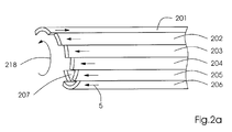
- Die Device 11 has a drive section 300 which has movable rods 201, 202, 203, 204, 205, 206, etc. continuously rotates and is conveyed as with reference to Fig. 2a and Fig. 2b described below.
- a strip 32 which is preferably made of steel, and two may have overlapping pieces of tape fed to the device 11, the tape so unwinds that a carrier sleeve 33 is formed.
- a first one belonging to device 1 comprises Tape casting device 20 for producing a compressible layer of urethane 21 and a blowing device 22.
- the urethane feed 21 can be a plurality of separate ones Sections include, for example, an isocyanate section Vulcanization section and a mixing chamber, as well as other material sections. Urethane from the feed 21 is through the blowing device 22 in the mixing chamber foamed and emerges from a nozzle 23 with an end mouthpiece. The foamed In this way, urethane is applied to the carrier sleeve 33 in order to make it compressible Form layer 34, which is illustrative with the applied liquid tapes is shown in the form of a spiral. In reality, the applied liquid flow Straps together and become hard to form a seamless, channelless compressible layer 34 to build.
- a squeegee or scraper knife 55 may contact urethane layer 34 and one Grinder 56 can smooth layer 34 to remove imperfections, such as For example, to reduce curls in layer 34.
- a second belt casting device 30 is used to compress the compressible layer 34
- Device 1 includes a reinforcement layer 42 in section 130 of a third station applied.
- the tape casting device 30 may have a urethane feed 31 and a nozzle 36 to apply the urethane.
- the hardness test value of the urethane is preferably about 100 Shore A. Again the applied urethane flows together and becomes hard to form a seamless and channelless reinforcement layer 42.
- a grinder 58 may be used to the A scraper knife 57 and can reduce imperfections in layer 42 .
- a third belt casting device 40 pulls out a belt Urethane to form a pressure layer 45 over the reinforcement layer 42.
- the urethane the printing layer preferably has a hardness test value of about 60 Shore A.
- the applied print layer forms a seamless and channelless layer during hardening. If , a scraper knife 51 and a grinder 50 can be used for correction or reducing imperfections, such as curls, in the Print layer 45 can be used.
- the printing blanket begins its movement in the direction of the Arrows 5 continue until a desired length is reached and cut the blanket is, for example by a rotating knife or a rotating saw.
- the sleeve is from rods 201-210 (see FIGS. 2a and 2b) held, and can be supported in sections 120, 130 and 140 by bottom brackets become.
- FIG. 2a is a closer view of the operation of the rods 201, 202, 203, 204, 205, 206, 207 rotating in the direction of 218.
- the bars turn, nine become at the same time of the ten bars moved towards 5.
- a rod is in the most axially distant position Reached direction 5, it is pushed back in the opposite direction 5, as for Rod 201 shown in Fig. 2a.
- This movement hampers the transfer of the sleeve in Direction 5 not, because the other nine rods continue to push the sleeve in direction 5.
- the rod 201 is pushed back, it begins to move in the direction 5 again move.
- 2b shows a cross-sectional view of the rods 201, 202, 203, 204, 205, 206, 207, 208, 209 and 210 together with the drive device 300 which rotates the rods and forwarded, for example through warehouse 260.
- Fig. 3 shows an alternative embodiment, in which the sleeve from a transport device 400 is transported through three revolving belt casting devices 220, 230, 240, which each the compressible layer, the reinforcement layer or the pressure layer Instruct.
- the layers can be made of materials of the same type as those shown in FIG. 1 Layers 34, 42 and 45.
- FIG. 4 shows a cross-sectional view of the printing blanket 100 with the carrier sleeve trained sleeve 33, the compressible layer 34, the reinforcing layer 42 and the Print layer 45.
- compressible layer refers to a polymeric one Material that has been made compressible by one of the known methods, for what for example the use of microspheres, blowing agents, foaming agents or Wash out count. Examples of these materials are described, for example, in US Pat. No. 5,768,990, US 5,553,541, US 5,440,981, US 5,429,048, US 5,323,702 and US 5,304,267.
- printing layer or elastomeric image transfer means Material on a polymeric material such as urethane that is transferable an image from an offset printing plate or other print image carrier onto a Roll or sheet material in a print quality that meets the requirements of corresponds to the respective printing application.
- the blanket also has a base layer may include between the support sleeve 33 and the compressible layer 34.
- the printing blanket according to the invention preferably comprises a compressible, a reinforcing and a pressure layer - it is also possible to produce printing blankets with fewer or with additional layers.
- a printing blanket according to the invention if this is for a specific application it makes sense to have a carrier sleeve and a printing layer, or a carrier sleeve include compressible layer and a pressure layer.
- a printing blanket according to the invention also has several compressible layers, could comprise several construction layers or several reinforcement layers.
- the reinforcement layer is preferably formed from urethane
- the Reinforcement layer also made of wrap or plastic tape, cord or thread to be formed around the work piece.
- Can also cross-spray extruder heads Strips are used to form some of the layers that are not cast by tape getting produced.
- the temperature of the flowable material can vary from the respective Belt casting devices are checked.
- the nozzles can also have mouthpieces have whose shape can be changed to change the To cause tape dimensions.
- the temperature and shape are Design nozzles so that a steady flow of flowable material onto the substrate flows. Flow speed, temperature, nozzle shape and speed of rotation of the Substrate can be changed to the desired properties for the to get different layers, for example the thickness of the layer.
Landscapes
- Printing Plates And Materials Therefor (AREA)
Applications Claiming Priority (2)
| Application Number | Priority Date | Filing Date | Title |
|---|---|---|---|
| US09/716,696 US6615721B1 (en) | 2000-11-20 | 2000-11-20 | Method and device for manufacturing a tubular lithographic printing blanket |
| US716696 | 2000-11-20 |
Publications (3)
| Publication Number | Publication Date |
|---|---|
| EP1208996A2 true EP1208996A2 (fr) | 2002-05-29 |
| EP1208996A3 EP1208996A3 (fr) | 2004-07-28 |
| EP1208996B1 EP1208996B1 (fr) | 2006-06-28 |
Family
ID=24879053
Family Applications (1)
| Application Number | Title | Priority Date | Filing Date |
|---|---|---|---|
| EP01126529A Expired - Lifetime EP1208996B1 (fr) | 2000-11-20 | 2001-11-14 | Appareil pour la production de blanchets d'impression tubulaires |
Country Status (7)
| Country | Link |
|---|---|
| US (1) | US6615721B1 (fr) |
| EP (1) | EP1208996B1 (fr) |
| JP (1) | JP4593849B2 (fr) |
| CN (1) | CN1355099A (fr) |
| AT (1) | ATE331634T1 (fr) |
| DE (2) | DE10155681A1 (fr) |
| HK (1) | HK1047262A1 (fr) |
Cited By (3)
| Publication number | Priority date | Publication date | Assignee | Title |
|---|---|---|---|---|
| FR2922154A1 (fr) * | 2007-10-11 | 2009-04-17 | Goss Int Montataire Sa | Unite d'impression et son utilisation |
| EP2085246A1 (fr) * | 2008-02-04 | 2009-08-05 | ROSSINI S.p.A. | Porte-blanchet et cylindre et procédé de fabrication correspondant |
| EP3495145A1 (fr) * | 2017-12-05 | 2019-06-12 | Tampoprint AG | Bande continue en tant que support intermédiaire d'impression pour un dispositif destiné à l'impression indirect d'une pièce pouvant être déroulée |
Families Citing this family (12)
| Publication number | Priority date | Publication date | Assignee | Title |
|---|---|---|---|---|
| US20020119323A1 (en) * | 2000-12-15 | 2002-08-29 | Johann Weinert | Compressible polyurethane layer and process for the preparation therof |
| US6779451B2 (en) | 2001-06-27 | 2004-08-24 | Heidelberger Druckmaschinen Ag | Flexible tubular printing blanket |
| US6874232B2 (en) * | 2003-05-21 | 2005-04-05 | Stowe Woodward, Llc | Method for forming cover for industrial roll |
| US7104198B2 (en) * | 2004-03-08 | 2006-09-12 | Goss International Americas, Inc. | Printing blanket with convex outer print surface |
| US10287731B2 (en) * | 2005-11-08 | 2019-05-14 | Stowe Woodward Licensco Llc | Abrasion-resistant rubber roll cover with polyurethane coating |
| US20080034998A1 (en) * | 2006-08-08 | 2008-02-14 | Byers Joseph L | Method of making a printing blanket or sleeve including cast polyurethane layers |
| US20080038025A1 (en) * | 2006-08-14 | 2008-02-14 | Eastman Kodak Company | Intermediate transfer member |
| US7976658B2 (en) * | 2006-08-14 | 2011-07-12 | Eastman Kodak Company | Method of manufacturing a low cost intermediate transfer member |
| US20080070042A1 (en) * | 2006-09-20 | 2008-03-20 | Day International, Inc. | Printing blanket or sleeve including thermoplastic polyurethane or thermoplastic polyurethane alloy layers |
| US8409698B2 (en) * | 2007-11-30 | 2013-04-02 | Day International, Inc. | Image transfer product including a thin printing surface layer |
| US20100307356A1 (en) * | 2008-02-04 | 2010-12-09 | Felice Rossini | Bridged sleeve/cylinder and method of making same for web offset printing machines |
| KR102124156B1 (ko) * | 2018-08-21 | 2020-06-17 | 김순호 | 효율적인 옵셋인쇄기 블랭킷 제조 시스템 및 그 시스템으로 교체수리한 블랭킷을 갖는 옵셋인쇄장치 |
Family Cites Families (15)
| Publication number | Priority date | Publication date | Assignee | Title |
|---|---|---|---|---|
| DE3943746C2 (de) * | 1989-03-18 | 1998-04-02 | Roland Man Druckmasch | Rotationsdruckmaschine mit einer beschichteten Trägerhülse |
| US5553541A (en) | 1989-10-05 | 1996-09-10 | Heidelberg Harris Inc | Gapless tubular printing blanket |
| US5429048A (en) | 1989-10-05 | 1995-07-04 | Gaffney; John M. | Offset lithographic printing press |
| US5352507A (en) * | 1991-04-08 | 1994-10-04 | W. R. Grace & Co.-Conn. | Seamless multilayer printing blanket |
| CA2068629C (fr) | 1991-05-14 | 1996-05-07 | James B. Vrotacoe | Blanchet d'imprimerie tubulaire sans passage |
| DE4123920C2 (de) * | 1991-07-19 | 1994-04-14 | Bayer Ag | Verfahren und Vorrichtung zum Herstellen von gewickelten Rohren |
| US5206992A (en) * | 1992-06-12 | 1993-05-04 | American Roller Company | Compressible roller |
| US5301610A (en) * | 1993-04-30 | 1994-04-12 | E. I. Du Pont De Nemours And Company | Method and apparatus for making spiral wound sleeves for printing cylinders and product thereof |
| US5544584A (en) * | 1994-12-09 | 1996-08-13 | Thompson Urethane Products | Process for producing polymer-covered flexographic printing sleeves |
| US5798019A (en) * | 1995-09-29 | 1998-08-25 | E. I. Du Pont De Nemours And Company | Methods and apparatus for forming cylindrical photosensitive elements |
| US5700343A (en) * | 1996-01-16 | 1997-12-23 | Reeves Brothers, Inc. | Preparation of cylindrical blanket by spreading of compressible layer |
| DE19720549A1 (de) * | 1997-05-16 | 1998-11-19 | Heidelberger Druckmasch Ag | Verfahren zur Herstellung von zylindrischen Beschichtungsträgern |
| DE19720551A1 (de) * | 1997-05-16 | 1998-11-19 | Heidelberger Druckmasch Ag | Basisträgerhülse für Rotationsdruckmaschinen |
| JP2000118164A (ja) * | 1998-10-14 | 2000-04-25 | Kinyosha Co Ltd | オフセット印刷用ブランケット及びその製造方法 |
| US6257140B1 (en) * | 1999-12-27 | 2001-07-10 | Heidelberger Druckmaschinen Ag | Continuous process gapless tubular lithographic printing blanket |
-
2000
- 2000-11-20 US US09/716,696 patent/US6615721B1/en not_active Expired - Fee Related
-
2001
- 2001-10-26 CN CN01134301A patent/CN1355099A/zh active Pending
- 2001-11-13 DE DE10155681A patent/DE10155681A1/de not_active Withdrawn
- 2001-11-14 DE DE50110319T patent/DE50110319D1/de not_active Expired - Lifetime
- 2001-11-14 EP EP01126529A patent/EP1208996B1/fr not_active Expired - Lifetime
- 2001-11-14 AT AT01126529T patent/ATE331634T1/de not_active IP Right Cessation
- 2001-11-16 JP JP2001352120A patent/JP4593849B2/ja not_active Expired - Fee Related
-
2002
- 2002-12-12 HK HK02109016.9A patent/HK1047262A1/zh unknown
Cited By (3)
| Publication number | Priority date | Publication date | Assignee | Title |
|---|---|---|---|---|
| FR2922154A1 (fr) * | 2007-10-11 | 2009-04-17 | Goss Int Montataire Sa | Unite d'impression et son utilisation |
| EP2085246A1 (fr) * | 2008-02-04 | 2009-08-05 | ROSSINI S.p.A. | Porte-blanchet et cylindre et procédé de fabrication correspondant |
| EP3495145A1 (fr) * | 2017-12-05 | 2019-06-12 | Tampoprint AG | Bande continue en tant que support intermédiaire d'impression pour un dispositif destiné à l'impression indirect d'une pièce pouvant être déroulée |
Also Published As
| Publication number | Publication date |
|---|---|
| HK1047262A1 (zh) | 2003-02-14 |
| DE10155681A1 (de) | 2002-07-11 |
| JP4593849B2 (ja) | 2010-12-08 |
| CN1355099A (zh) | 2002-06-26 |
| JP2002200860A (ja) | 2002-07-16 |
| US6615721B1 (en) | 2003-09-09 |
| EP1208996B1 (fr) | 2006-06-28 |
| DE50110319D1 (de) | 2006-08-10 |
| EP1208996A3 (fr) | 2004-07-28 |
| ATE331634T1 (de) | 2006-07-15 |
Similar Documents
| Publication | Publication Date | Title |
|---|---|---|
| EP1208996B1 (fr) | Appareil pour la production de blanchets d'impression tubulaires | |
| EP0614838B1 (fr) | Douille de pression interchangeable | |
| DE69905655T2 (de) | Verfahren und Vorrichtung zur Laminierung bandförmigen unvulkanisierten Kautschukmaterials | |
| DE60212507T2 (de) | Verfahren zur Herstellung eines Formkörpers aus Gummi | |
| DE69916709T2 (de) | Verfahren und Vorrichtung zum Auflegen von Kautschukmaterialien für Reifenaufbauteile | |
| EP0514344A1 (fr) | Blanchet d'impression tubulaire sans fente | |
| EP0166245A2 (fr) | Procédé et appareil pour la fabrication en continu de corps creux tubulaires, en particulier de tuyaux, tubes et revêtements internes pour ceux-ci à partir d'une matière liquide telle qu'un mélange réactif ou une masse fondue | |
| EP1112860B1 (fr) | Méthode pour la préparation continue des blanchets d'impression tubulaires, de préférence sans ligne de soudure en caoutchouc pour des machines d'impression offset | |
| CH424696A (de) | Druckdecke für Druckmaschinen | |
| EP1275520B1 (fr) | Procédé de fabrication d'un blanchet d'impression tubulaire flexible en caoutchouc | |
| DE10225541A1 (de) | Verfahren und Vorrichtung zum Herstellen eines hülsenförmigen Gummituchs | |
| DD151132A5 (de) | Verfahren und vorrichtung zur bildung von innerlinern fuer die produktion von fahrzeugreifen | |
| DE60222839T2 (de) | Verfahren zur Herstellung eines Luftreifens aufweisend eine kordverstärkte Schicht | |
| DE2109809A1 (de) | Bandaufbauvorrichtung | |
| DE2355847A1 (de) | Verfahren und vorrichtung zur herstellung biegsamer rohre mit drahteinlage | |
| EP1316423A1 (fr) | Rouleau tramé et méthode pour sa production et retraitement | |
| DE60318956T2 (de) | Verfahren und vorrichtung zum auftragen einer beschichtigung auf einen um eine achse rotierenden körper | |
| DE19931002A1 (de) | Vorrichtung zum Verstellen des effektiven Zylinderdurchmessers | |
| DE2834246A1 (de) | Vorrichtung zum lochen von materialbahnen | |
| EP2707203B1 (fr) | Dispositif comprenant un systeme tete-rouleau | |
| DE10046559A1 (de) | Druckklischee-Montagesystem | |
| DE60026573T2 (de) | Verfahren und vorrichtung zur automatischen abtrennung des stützgewebes von einem gummiband | |
| EP2050560A1 (fr) | Dispositif d'application de bandes de matériau sur un pneu cru ou un tambour de fabrication | |
| DE3881702T2 (de) | Dornkonstruktion. | |
| EP1390202B1 (fr) | Procede de production d'une plaque d'impression pouvant etre directement gravee au laser, et plaque d'impression produite selon ledit procede |
Legal Events
| Date | Code | Title | Description |
|---|---|---|---|
| PUAI | Public reference made under article 153(3) epc to a published international application that has entered the european phase |
Free format text: ORIGINAL CODE: 0009012 |
|
| AK | Designated contracting states |
Kind code of ref document: A2 Designated state(s): AT BE CH CY DE DK ES FI FR GB GR IE IT LI LU MC NL PT SE TR |
|
| AX | Request for extension of the european patent |
Free format text: AL;LT;LV;MK;RO;SI |
|
| RIC1 | Information provided on ipc code assigned before grant |
Ipc: 7B 41N 7/00 A Ipc: 7B 41N 10/02 B |
|
| 17P | Request for examination filed |
Effective date: 20040407 |
|
| PUAL | Search report despatched |
Free format text: ORIGINAL CODE: 0009013 |
|
| AK | Designated contracting states |
Kind code of ref document: A3 Designated state(s): AT BE CH CY DE DK ES FI FR GB GR IE IT LI LU MC NL PT SE TR |
|
| AX | Request for extension of the european patent |
Extension state: AL LT LV MK RO SI |
|
| RAP1 | Party data changed (applicant data changed or rights of an application transferred) |
Owner name: GOSS INTERNATIONAL AMERICAS, INC. |
|
| AKX | Designation fees paid |
Designated state(s): AT BE CH CY DE DK ES FI FR GB GR IE IT LI LU MC NL PT SE TR |
|
| GRAP | Despatch of communication of intention to grant a patent |
Free format text: ORIGINAL CODE: EPIDOSNIGR1 |
|
| GRAC | Information related to communication of intention to grant a patent modified |
Free format text: ORIGINAL CODE: EPIDOSCIGR1 |
|
| GRAS | Grant fee paid |
Free format text: ORIGINAL CODE: EPIDOSNIGR3 |
|
| GRAA | (expected) grant |
Free format text: ORIGINAL CODE: 0009210 |
|
| AK | Designated contracting states |
Kind code of ref document: B1 Designated state(s): AT BE CH CY DE DK ES FI FR GB GR IE IT LI LU MC NL PT SE TR |
|
| PG25 | Lapsed in a contracting state [announced via postgrant information from national office to epo] |
Ref country code: IT Free format text: LAPSE BECAUSE OF FAILURE TO SUBMIT A TRANSLATION OF THE DESCRIPTION OR TO PAY THE FEE WITHIN THE PRESCRIBED TIME-LIMIT;WARNING: LAPSES OF ITALIAN PATENTS WITH EFFECTIVE DATE BEFORE 2007 MAY HAVE OCCURRED AT ANY TIME BEFORE 2007. THE CORRECT EFFECTIVE DATE MAY BE DIFFERENT FROM THE ONE RECORDED. Effective date: 20060628 Ref country code: FI Free format text: LAPSE BECAUSE OF FAILURE TO SUBMIT A TRANSLATION OF THE DESCRIPTION OR TO PAY THE FEE WITHIN THE PRESCRIBED TIME-LIMIT Effective date: 20060628 Ref country code: IE Free format text: LAPSE BECAUSE OF FAILURE TO SUBMIT A TRANSLATION OF THE DESCRIPTION OR TO PAY THE FEE WITHIN THE PRESCRIBED TIME-LIMIT Effective date: 20060628 Ref country code: NL Free format text: LAPSE BECAUSE OF FAILURE TO SUBMIT A TRANSLATION OF THE DESCRIPTION OR TO PAY THE FEE WITHIN THE PRESCRIBED TIME-LIMIT Effective date: 20060628 |
|
| REG | Reference to a national code |
Ref country code: GB Ref legal event code: FG4D Free format text: NOT ENGLISH |
|
| REG | Reference to a national code |
Ref country code: CH Ref legal event code: EP |
|
| REG | Reference to a national code |
Ref country code: CH Ref legal event code: NV Representative=s name: KIRKER & CIE SA |
|
| GBT | Gb: translation of ep patent filed (gb section 77(6)(a)/1977) |
Effective date: 20060711 |
|
| REG | Reference to a national code |
Ref country code: IE Ref legal event code: FG4D Free format text: LANGUAGE OF EP DOCUMENT: GERMAN |
|
| REF | Corresponds to: |
Ref document number: 50110319 Country of ref document: DE Date of ref document: 20060810 Kind code of ref document: P |
|
| PG25 | Lapsed in a contracting state [announced via postgrant information from national office to epo] |
Ref country code: DK Free format text: LAPSE BECAUSE OF FAILURE TO SUBMIT A TRANSLATION OF THE DESCRIPTION OR TO PAY THE FEE WITHIN THE PRESCRIBED TIME-LIMIT Effective date: 20060928 Ref country code: SE Free format text: LAPSE BECAUSE OF FAILURE TO SUBMIT A TRANSLATION OF THE DESCRIPTION OR TO PAY THE FEE WITHIN THE PRESCRIBED TIME-LIMIT Effective date: 20060928 |
|
| PG25 | Lapsed in a contracting state [announced via postgrant information from national office to epo] |
Ref country code: ES Free format text: LAPSE BECAUSE OF FAILURE TO SUBMIT A TRANSLATION OF THE DESCRIPTION OR TO PAY THE FEE WITHIN THE PRESCRIBED TIME-LIMIT Effective date: 20061009 |
|
| PG25 | Lapsed in a contracting state [announced via postgrant information from national office to epo] |
Ref country code: PT Free format text: LAPSE BECAUSE OF FAILURE TO SUBMIT A TRANSLATION OF THE DESCRIPTION OR TO PAY THE FEE WITHIN THE PRESCRIBED TIME-LIMIT Effective date: 20061128 |
|
| PG25 | Lapsed in a contracting state [announced via postgrant information from national office to epo] |
Ref country code: BE Free format text: LAPSE BECAUSE OF NON-PAYMENT OF DUE FEES Effective date: 20061130 Ref country code: MC Free format text: LAPSE BECAUSE OF NON-PAYMENT OF DUE FEES Effective date: 20061130 |
|
| NLV1 | Nl: lapsed or annulled due to failure to fulfill the requirements of art. 29p and 29m of the patents act | ||
| ET | Fr: translation filed | ||
| REG | Reference to a national code |
Ref country code: IE Ref legal event code: FD4D |
|
| PLBE | No opposition filed within time limit |
Free format text: ORIGINAL CODE: 0009261 |
|
| STAA | Information on the status of an ep patent application or granted ep patent |
Free format text: STATUS: NO OPPOSITION FILED WITHIN TIME LIMIT |
|
| 26N | No opposition filed |
Effective date: 20070329 |
|
| BERE | Be: lapsed |
Owner name: GOSS INTERNATIONAL AMERICAS, INC. Effective date: 20061130 |
|
| PG25 | Lapsed in a contracting state [announced via postgrant information from national office to epo] |
Ref country code: AT Free format text: LAPSE BECAUSE OF NON-PAYMENT OF DUE FEES Effective date: 20061114 |
|
| PG25 | Lapsed in a contracting state [announced via postgrant information from national office to epo] |
Ref country code: GR Free format text: LAPSE BECAUSE OF FAILURE TO SUBMIT A TRANSLATION OF THE DESCRIPTION OR TO PAY THE FEE WITHIN THE PRESCRIBED TIME-LIMIT Effective date: 20060929 |
|
| PG25 | Lapsed in a contracting state [announced via postgrant information from national office to epo] |
Ref country code: TR Free format text: LAPSE BECAUSE OF FAILURE TO SUBMIT A TRANSLATION OF THE DESCRIPTION OR TO PAY THE FEE WITHIN THE PRESCRIBED TIME-LIMIT Effective date: 20060628 Ref country code: LU Free format text: LAPSE BECAUSE OF NON-PAYMENT OF DUE FEES Effective date: 20061114 |
|
| PG25 | Lapsed in a contracting state [announced via postgrant information from national office to epo] |
Ref country code: CY Free format text: LAPSE BECAUSE OF FAILURE TO SUBMIT A TRANSLATION OF THE DESCRIPTION OR TO PAY THE FEE WITHIN THE PRESCRIBED TIME-LIMIT Effective date: 20060628 |
|
| PGFP | Annual fee paid to national office [announced via postgrant information from national office to epo] |
Ref country code: FR Payment date: 20101202 Year of fee payment: 10 |
|
| PGFP | Annual fee paid to national office [announced via postgrant information from national office to epo] |
Ref country code: CH Payment date: 20101124 Year of fee payment: 10 Ref country code: DE Payment date: 20101126 Year of fee payment: 10 |
|
| PGFP | Annual fee paid to national office [announced via postgrant information from national office to epo] |
Ref country code: GB Payment date: 20101124 Year of fee payment: 10 |
|
| REG | Reference to a national code |
Ref country code: CH Ref legal event code: PL |
|
| GBPC | Gb: european patent ceased through non-payment of renewal fee |
Effective date: 20111114 |
|
| PG25 | Lapsed in a contracting state [announced via postgrant information from national office to epo] |
Ref country code: LI Free format text: LAPSE BECAUSE OF NON-PAYMENT OF DUE FEES Effective date: 20111130 Ref country code: CH Free format text: LAPSE BECAUSE OF NON-PAYMENT OF DUE FEES Effective date: 20111130 |
|
| REG | Reference to a national code |
Ref country code: FR Ref legal event code: ST Effective date: 20120731 |
|
| REG | Reference to a national code |
Ref country code: DE Ref legal event code: R119 Ref document number: 50110319 Country of ref document: DE Effective date: 20120601 |
|
| PG25 | Lapsed in a contracting state [announced via postgrant information from national office to epo] |
Ref country code: GB Free format text: LAPSE BECAUSE OF NON-PAYMENT OF DUE FEES Effective date: 20111114 |
|
| PG25 | Lapsed in a contracting state [announced via postgrant information from national office to epo] |
Ref country code: FR Free format text: LAPSE BECAUSE OF NON-PAYMENT OF DUE FEES Effective date: 20111130 |
|
| PG25 | Lapsed in a contracting state [announced via postgrant information from national office to epo] |
Ref country code: DE Free format text: LAPSE BECAUSE OF NON-PAYMENT OF DUE FEES Effective date: 20120601 |