EP1208998A1 - Leimwerk zum Auftragen eines Klebstoffes - Google Patents
Leimwerk zum Auftragen eines Klebstoffes Download PDFInfo
- Publication number
- EP1208998A1 EP1208998A1 EP00811089A EP00811089A EP1208998A1 EP 1208998 A1 EP1208998 A1 EP 1208998A1 EP 00811089 A EP00811089 A EP 00811089A EP 00811089 A EP00811089 A EP 00811089A EP 1208998 A1 EP1208998 A1 EP 1208998A1
- Authority
- EP
- European Patent Office
- Prior art keywords
- adhesive
- squeegee
- unit according
- glue unit
- electric motor
- Prior art date
- Legal status (The legal status is an assumption and is not a legal conclusion. Google has not performed a legal analysis and makes no representation as to the accuracy of the status listed.)
- Granted
Links
- 239000000853 adhesive Substances 0.000 title claims description 18
- 230000001070 adhesive effect Effects 0.000 title claims description 18
- 239000003292 glue Substances 0.000 claims abstract description 14
- 239000002313 adhesive film Substances 0.000 claims description 2
- 238000004026 adhesive bonding Methods 0.000 description 10
- 239000011230 binding agent Substances 0.000 description 3
- 230000015572 biosynthetic process Effects 0.000 description 1
- 230000002349 favourable effect Effects 0.000 description 1
- 238000004519 manufacturing process Methods 0.000 description 1
- 238000007790 scraping Methods 0.000 description 1
Images
Classifications
-
- B—PERFORMING OPERATIONS; TRANSPORTING
- B42—BOOKBINDING; ALBUMS; FILES; SPECIAL PRINTED MATTER
- B42C—BOOKBINDING
- B42C9/00—Applying glue or adhesive peculiar to bookbinding
- B42C9/0006—Applying glue or adhesive peculiar to bookbinding by applying adhesive to a stack of sheets
- B42C9/0012—Applying glue or adhesive peculiar to bookbinding by applying adhesive to a stack of sheets with a roller
-
- Y—GENERAL TAGGING OF NEW TECHNOLOGICAL DEVELOPMENTS; GENERAL TAGGING OF CROSS-SECTIONAL TECHNOLOGIES SPANNING OVER SEVERAL SECTIONS OF THE IPC; TECHNICAL SUBJECTS COVERED BY FORMER USPC CROSS-REFERENCE ART COLLECTIONS [XRACs] AND DIGESTS
- Y10—TECHNICAL SUBJECTS COVERED BY FORMER USPC
- Y10S—TECHNICAL SUBJECTS COVERED BY FORMER USPC CROSS-REFERENCE ART COLLECTIONS [XRACs] AND DIGESTS
- Y10S156/00—Adhesive bonding and miscellaneous chemical manufacture
- Y10S156/908—Laminating sheet to entire edge of block and both adjacent opposite surfaces, e.g. bookbinding
-
- Y—GENERAL TAGGING OF NEW TECHNOLOGICAL DEVELOPMENTS; GENERAL TAGGING OF CROSS-SECTIONAL TECHNOLOGIES SPANNING OVER SEVERAL SECTIONS OF THE IPC; TECHNICAL SUBJECTS COVERED BY FORMER USPC CROSS-REFERENCE ART COLLECTIONS [XRACs] AND DIGESTS
- Y10—TECHNICAL SUBJECTS COVERED BY FORMER USPC
- Y10T—TECHNICAL SUBJECTS COVERED BY FORMER US CLASSIFICATION
- Y10T156/00—Adhesive bonding and miscellaneous chemical manufacture
- Y10T156/17—Surface bonding means and/or assemblymeans with work feeding or handling means
- Y10T156/1798—Surface bonding means and/or assemblymeans with work feeding or handling means with liquid adhesive or adhesive activator applying means
Definitions
- the invention relates to a gluing unit for applying an adhesive to the spine or adjacent areas of a printed sheet brought together in a conveying device, consisting of a tray containing adhesive, into which at least one adhesive receiving and transferring to the spine of the book block, in the same direction as the book block Driven applicator roller immersed, which above the glue level in the tub is assigned a squeegee film which determines the glue film thickness to be transferred to the book block spine and which has an actuating member for adjustment, due to the variable distance from the applicator roller.
- a gluing unit for applying an adhesive to the spine or adjacent areas of a printed sheet brought together in a conveying device, consisting of a tray containing adhesive, into which at least one adhesive receiving and transferring to the spine of the book block, in the same direction as the book block Driven applicator roller immersed, which above the glue level in the tub is assigned a squeegee film which determines the glue film thickness to be transferred to the book block spine and which has an actu
- the adhesive is transferred with two rollers arranged one behind the other and is mechanically minimally driven between the sheet edges, so that the sheets are embedded in the transferred adhesive.
- the amount of adhesive to be applied is metered by a controllable doctor blade so that it cannot penetrate the inside of the book.
- the roller height setting and the squeegee position must be carefully coordinated.
- the excess adhesive applied is then compensated for by a vertically adjustable doctor blade or a leveling roller.
- the squeegees are adjusted or adjusted manually or via motor-driven cams which act on a control lever connected to the squeegee shaft.
- Devices are also known in which the doctor blade can be adjusted by means of servomotors which control a differential or planetary gear.
- Squeegees driven by pneumatic cylinders, to which an adjustable stop is assigned, are known.
- this object is achieved in that the Actuator of the squeegee with the drive member of a controllable Electric motor is connected to the drive, whereby opposite the known designs require less space.
- the actuator of the squeegee is advantageous as pivotable Shaft formed, the direct drive connection in a simple manner allowed with an electric motor.
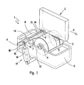
- FIG. 1 and 2 show a gluing unit 1 of an adhesive binder provided for the production of book blocks 2 formed from printed sheets.
- the book blocks 2 transported in the conveying direction F in clamping devices of a conveying device (not visible) are glued to their spine 3 protruding from the clamping device when passing through the gluing unit 1.
- an application roller 4 rotating about a direction transverse to the conveying direction F is provided, which takes up adhesive 5 with the jacket surface immersed in the adhesive 5 occurring in a trough 6 and transfers it overly thick to the back 3 of the book block 2.
- the adhesive film 7 drawn on the application roller 4 passes through an adjustable doctor blade 8, which determines the amount of the adhesive 5 to be transferred to the back 3.
- the distance of the application roller 4 to the back 3 of the book block 2 as well as the distance of the squeegee 8 from the application roller 4 are adjustable or adjustable.
- the back 3 of the book block 2 and the jacket of the application roller 4 have a direction of movement and speed in the same direction in the area of the adhesive transfer.
- the doctor blade 8 scraping off the excess adhesive 5 on the application roller 4 or forming a smooth film surface has a cutting edge-like end edge 9.
- the adhesive 5 stripped off by the squeegee 8 on the application roller 4 flows back into the trough 6.
- a shaft 12 is provided for actuating the squeegee 8, which can be pivoted about an axis 11 running parallel to the axis of rotation 10 of the application roller 4, to which a scraper member 13 is attached.
- the shaft 12 is supported on pivot bearings 14 which are anchored to the tub 6.
- One end of the shaft 12 has a tab-like lever 15 which is connected to a drive rod 16 of a linear motor 17 articulated on a machine frame or the tub 6.
- the drive rod 16 is designed as an extension of the armature 18 (not visible) of the linear motor 17.
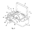
- the difference is in Formation of the electric motor 17, the one after an arc section trained anchor 18, the elongated Radial ends of a shaft 12 as an actuator protruding arms 19 forming an obtuse angle are.
Landscapes
- Coating Apparatus (AREA)
- Folding Of Thin Sheet-Like Materials, Special Discharging Devices, And Others (AREA)
Abstract
Description
Die aufzutragende Klebstoffmenge wird durch ein steuerbares Rakel dosiert, damit sie u.a. nicht in das Buchinnere eindringen kann. Die Walzenhöheneinstellung und die Rakelstellung sind dabei sorgfältig aufeinander abzustimmen. Der zuviel aufgetragene Klebstoff wird abschliessend von einem vertikal verstellbaren Abstreichrakel oder einer Egalisierwalze ausgeglichen.
Auch von Pneumatikzylindern angetriebene Rakel, denen ein verstellbarer Anschlag zugeordnet ist, sind bekannt.
- Fig. 1
- eine räumliche Darstellung eines Leimwerkes eines Klebebinders und
- Fig. 2
- eine räumliche Darstellung eines alternativen Leimwerks eines Klebebinders.
Der den überschüssigen Klebstoff 5 an der Auftragswalze 4 abstreifende bzw. eine glatte Filmoberfläche bildende Rakel 8 weist hierzu eine schneidenähnliche Endkante 9 auf. Der vom Rakel 8 an der Auftragswalze 4 abgestreifte Klebstoff 5 fliesst in die Wanne 6 zurück.
Bei dem in Fig. 1 veranschaulichten Leimwerk 1 ist zur Betätigung des um eine parallel zur Drehachse 10 der Auftragswalze 4 verlaufende Achse 11 schwenkbaren Rakels 8 eine Welle 12 vorgesehen, an der ein Abstreiforgan 13 befestigt ist. Die Welle 12 lagert an Schwenklagern 14, die an der Wanne 6 verankert sind. Das eine Ende der Welle 12 weist einen laschenartigen Hebel 15 auf, der mit einer Antriebsstange 16 eines an einem Maschinengestell oder der Wanne 6 angelenkten Linearmotors 17 verbunden ist. Die Antriebsstange 16 ist als Verlängerung des Ankers 18 (nicht sichtbar) des Linearmotors 17 ausgebildet.
Claims (7)
- Leimwerk (1) zum Auftragen eines Klebstoffes (5) auf den Rücken oder angrenzende Bereiche eines in einer Fördereinrichtung vorbeigeführten Buchblocks (2) zusammengetragener Druckbogen, bestehend aus einer Klebstoff (5) enthaltenden Wanne (6), in die wenigstens eine den Klebstoff (5) aufnehmende und an den Rücken (3) des Buchblocks (2) übertragende, gleichsinnig mit dem Buchblock (2) angetriebene Auftragswalze (4) eintaucht, welcher über dem Leimniveau in der Wanne (6) ein durch den veränderbaren Abstand von der Auftragswalze (4) die auf den Buchblockrücken (3) zu übertragende Klebstofffilmdicke bestimmender, zur Verstellung ein Betätigungsorgan aufweisender Rakel (8) zugeordnet ist, dadurch gekennzeichnet, dass das Betätigungsorgan des Rakels (8) mit dem Antriebsorgan (18) eines steuerbaren Elektromotors (17) antriebsverbunden ist.
- Leimwerk nach Anspruch 1, dadurch gekennzeichnet, dass das Betätigungsorgan des Rakels (8) als schwenkbare Welle (12) ausgebildet ist.
- Leimwerk nach Anspruch 2, dadurch gekennzeichnet, dass der Elektromotor (17) als Linearmotor ausgebildet ist.
- Leimwerk nach Anspruch 3, dadurch gekennzeichnet, dass ein Anker (18) des Linearmotors (17) mit dem Betätigungsorgan des Rakels (8) verbunden ist.
- Leimwerk nach Anspruch 4, dadurch gekennzeichnet, dass der Anker (18) des Linearmotors (17) um die Achse der Welle (12) oszillierend antreibbar und mit von der Welle (12) abstehenden, einen Kreissektor bildenden Auslegern (19) verbunden ist.
- Leimwerk nach Anspruch 2, dadurch gekennzeichnet, dass der Elektromotor (17) rotativ arbeitend ausgebildet ist.
- Leimwerk nach einem der Ansprüche 1 bis 6, dadurch gekennzeichnet, dass der Elektromotor mit einer programmierbaren Steuerung verbunden ist.
Priority Applications (4)
| Application Number | Priority Date | Filing Date | Title |
|---|---|---|---|
| EP00811089A EP1208998B1 (de) | 2000-11-17 | 2000-11-17 | Leimwerk zum Auftragen eines Klebstoffes |
| DE50014390T DE50014390D1 (de) | 2000-11-17 | 2000-11-17 | Leimwerk zum Auftragen eines Klebstoffes |
| JP2001304256A JP2002192041A (ja) | 2000-11-17 | 2001-09-28 | 接着剤を塗布するための糊付け装置 |
| US09/987,989 US6565658B2 (en) | 2000-11-17 | 2001-11-16 | Glue spreader |
Applications Claiming Priority (1)
| Application Number | Priority Date | Filing Date | Title |
|---|---|---|---|
| EP00811089A EP1208998B1 (de) | 2000-11-17 | 2000-11-17 | Leimwerk zum Auftragen eines Klebstoffes |
Publications (2)
| Publication Number | Publication Date |
|---|---|
| EP1208998A1 true EP1208998A1 (de) | 2002-05-29 |
| EP1208998B1 EP1208998B1 (de) | 2007-06-06 |
Family
ID=8175034
Family Applications (1)
| Application Number | Title | Priority Date | Filing Date |
|---|---|---|---|
| EP00811089A Expired - Lifetime EP1208998B1 (de) | 2000-11-17 | 2000-11-17 | Leimwerk zum Auftragen eines Klebstoffes |
Country Status (4)
| Country | Link |
|---|---|
| US (1) | US6565658B2 (de) |
| EP (1) | EP1208998B1 (de) |
| JP (1) | JP2002192041A (de) |
| DE (1) | DE50014390D1 (de) |
Cited By (5)
| Publication number | Priority date | Publication date | Assignee | Title |
|---|---|---|---|---|
| DE10242260A1 (de) * | 2002-09-12 | 2004-03-25 | Kolbus Gmbh & Co. Kg | Vorrichtung zum Auftragen eines Klebstoffs auf den Rücken oder rückennahen Bereichen der Seitenflächen eines Buchblocks |
| DE10242259A1 (de) * | 2002-09-12 | 2004-03-25 | Kolbus Gmbh & Co. Kg | Vorrichtung zum Auftragen eines Klebstoffs auf den Rücken oder rückennahen Seitenbereichen der Seitenflächen eines Buchblocks |
| EP1872964A1 (de) | 2006-06-30 | 2008-01-02 | Müller Martini Holding AG | Leimwerk für Buchblocks mit verstellbarer Rakel |
| CN102529471A (zh) * | 2011-12-20 | 2012-07-04 | 中国航空工业集团公司北京航空制造工程研究所 | 采用转印法形成树脂膜的方法 |
| CN104608518A (zh) * | 2015-03-03 | 2015-05-13 | 温州锐光机械有限公司 | 一种包本机的上胶系统 |
Families Citing this family (20)
| Publication number | Priority date | Publication date | Assignee | Title |
|---|---|---|---|---|
| US7314075B2 (en) * | 2003-04-04 | 2008-01-01 | Nisca Corporation | Adhesive dispensing apparatus and image forming apparatus |
| ITMI20042546A1 (it) * | 2004-12-29 | 2005-03-29 | Giovanni Gambini | Dispositivo per distribuire colla su un lembo di estremita' di un log su un log o su un'anima per log e relativo metodo |
| US8312834B2 (en) * | 2005-04-14 | 2012-11-20 | Hamilton Sundstrand Corporation | Apparatus for applying thin coating |
| WO2007034499A1 (en) * | 2005-09-26 | 2007-03-29 | Soreq Nuclear Research Center | Probe for tagging valuables based on dna-metal complex |
| JP2008172917A (ja) * | 2007-01-11 | 2008-07-24 | Hiwin Mikrosystem Corp | リニアモータ用切り屑排除構造 |
| JP4407719B2 (ja) * | 2007-04-26 | 2010-02-03 | コニカミノルタビジネステクノロジーズ株式会社 | 製本装置 |
| US7963733B2 (en) * | 2008-10-01 | 2011-06-21 | Perfect Systems, Llc | Apparatus for and a method of binding of a perfect bound book |
| DE102009031949A1 (de) | 2009-07-07 | 2011-01-13 | Kolbus Gmbh & Co. Kg | Vorrichtung zum Auftragen von Klebstoff auf einen Buchblock |
| US9242499B2 (en) | 2011-09-02 | 2016-01-26 | Horizon International Inc. | Glue application unit for perfect binding machine |
| JP5913330B2 (ja) * | 2011-09-16 | 2016-04-27 | ホリゾン・インターナショナル株式会社 | 無線綴じ製本装置の糊付けユニット |
| JP6149342B2 (ja) * | 2012-03-09 | 2017-06-21 | 大日本印刷株式会社 | 糊付装置、製本装置 |
| JP6065582B2 (ja) * | 2012-12-26 | 2017-01-25 | 大日本印刷株式会社 | 無線綴じ製本装置、糊塗布装置、ドクターブレード |
| US8920096B2 (en) | 2012-12-27 | 2014-12-30 | Donnie Donselman | Book binding adhesive application controller |
| JP2016043488A (ja) * | 2014-08-19 | 2016-04-04 | 株式会社Isowa | 糊付装置 |
| CN106515250B (zh) * | 2017-01-08 | 2017-11-03 | 周茂春 | 一种会计财务用的票据存根装订器 |
| US10864567B2 (en) * | 2018-04-17 | 2020-12-15 | Government Of The United States As Represented By The Secretary Of The Army | Systems and methods for electroprocessing a gun barrel using a moving electrode |
| CN111204146B (zh) * | 2020-01-07 | 2021-10-15 | 西安天成印务有限公司 | 一种薄册涂胶装置 |
| CN112776500B (zh) * | 2020-12-30 | 2023-11-14 | 深圳精密达智能机器有限公司 | 一种基于行星轮系的凸轮断胶装置 |
| CN113414053B (zh) * | 2021-07-13 | 2022-04-15 | 深圳市精联精密科技有限公司 | 一种仿形圆周涂胶机构及其涂胶方法 |
| CN113953134B (zh) * | 2021-10-22 | 2022-11-25 | 漳州市天辰纸品包装有限公司 | 一种用于纸制品包装箱的涂胶装置 |
Citations (3)
| Publication number | Priority date | Publication date | Assignee | Title |
|---|---|---|---|---|
| US5693142A (en) * | 1993-03-26 | 1997-12-02 | Nordson Corporation | Wheel applicator device for applying adhesive, especially to the spines of books during bookbinding |
| EP0839584A2 (de) * | 1996-11-01 | 1998-05-06 | Marquip, Inc. | Vorrichtung und Verfahren zum Auftragen von viskosen Flüssigkeiten auf ein Substrat |
| DE19722456A1 (de) * | 1997-05-28 | 1998-12-03 | Voith Sulzer Papiermasch Gmbh | Einrichtung zum Auftragen eines flüssigen oder pastösen Mediums auf eine laufende Materialbahn, insbesondere aus Papier oder Pappe |
Family Cites Families (5)
| Publication number | Priority date | Publication date | Assignee | Title |
|---|---|---|---|---|
| US4014287A (en) * | 1975-08-04 | 1977-03-29 | Comstock & Wescott, Inc. | High speed fluid applicator |
| DD144383A1 (de) * | 1979-08-13 | 1980-10-15 | Gerald Winker | Vorrichtung zum auftragen von schmelzklebstoff auf blockruecken |
| JPS6225254Y2 (de) * | 1981-06-03 | 1987-06-27 | ||
| CH662310A5 (de) * | 1983-11-22 | 1987-09-30 | Grapha Holding Ag | Buchbindemaschine. |
| JP3805490B2 (ja) * | 1997-06-20 | 2006-08-02 | ホリゾン・インターナショナル株式会社 | 用紙綴じ用糊付け装置 |
-
2000
- 2000-11-17 DE DE50014390T patent/DE50014390D1/de not_active Expired - Lifetime
- 2000-11-17 EP EP00811089A patent/EP1208998B1/de not_active Expired - Lifetime
-
2001
- 2001-09-28 JP JP2001304256A patent/JP2002192041A/ja active Pending
- 2001-11-16 US US09/987,989 patent/US6565658B2/en not_active Expired - Lifetime
Patent Citations (3)
| Publication number | Priority date | Publication date | Assignee | Title |
|---|---|---|---|---|
| US5693142A (en) * | 1993-03-26 | 1997-12-02 | Nordson Corporation | Wheel applicator device for applying adhesive, especially to the spines of books during bookbinding |
| EP0839584A2 (de) * | 1996-11-01 | 1998-05-06 | Marquip, Inc. | Vorrichtung und Verfahren zum Auftragen von viskosen Flüssigkeiten auf ein Substrat |
| DE19722456A1 (de) * | 1997-05-28 | 1998-12-03 | Voith Sulzer Papiermasch Gmbh | Einrichtung zum Auftragen eines flüssigen oder pastösen Mediums auf eine laufende Materialbahn, insbesondere aus Papier oder Pappe |
Cited By (9)
| Publication number | Priority date | Publication date | Assignee | Title |
|---|---|---|---|---|
| DE10242260A1 (de) * | 2002-09-12 | 2004-03-25 | Kolbus Gmbh & Co. Kg | Vorrichtung zum Auftragen eines Klebstoffs auf den Rücken oder rückennahen Bereichen der Seitenflächen eines Buchblocks |
| DE10242259A1 (de) * | 2002-09-12 | 2004-03-25 | Kolbus Gmbh & Co. Kg | Vorrichtung zum Auftragen eines Klebstoffs auf den Rücken oder rückennahen Seitenbereichen der Seitenflächen eines Buchblocks |
| US6908513B2 (en) | 2002-09-12 | 2005-06-21 | Kolbus Gmbh & Co. Kg | Device for applying an adhesive to the spine of an inner book or to areas of the lateral faces adjacent thereto |
| DE10242259B4 (de) * | 2002-09-12 | 2009-11-26 | Kolbus Gmbh & Co. Kg | Vorrichtung zum Auftragen eines Klebstoffs auf den Rücken oder rückennahen Bereich der Seitenflächen eines Buchblocks |
| EP1872964A1 (de) | 2006-06-30 | 2008-01-02 | Müller Martini Holding AG | Leimwerk für Buchblocks mit verstellbarer Rakel |
| US7959394B2 (en) | 2006-06-30 | 2011-06-14 | Müller Martini Holding AG | Glue applicator for applying an adhesive to the spine or adjacent areas of a book block being conducted past the glue applicator in a transport direction |
| CN102529471A (zh) * | 2011-12-20 | 2012-07-04 | 中国航空工业集团公司北京航空制造工程研究所 | 采用转印法形成树脂膜的方法 |
| CN104608518A (zh) * | 2015-03-03 | 2015-05-13 | 温州锐光机械有限公司 | 一种包本机的上胶系统 |
| CN104608518B (zh) * | 2015-03-03 | 2016-04-20 | 温州锐光机械有限公司 | 一种包本机的上胶系统 |
Also Published As
| Publication number | Publication date |
|---|---|
| US20020061241A1 (en) | 2002-05-23 |
| DE50014390D1 (de) | 2007-07-19 |
| EP1208998B1 (de) | 2007-06-06 |
| US6565658B2 (en) | 2003-05-20 |
| JP2002192041A (ja) | 2002-07-10 |
Similar Documents
| Publication | Publication Date | Title |
|---|---|---|
| EP1208998B1 (de) | Leimwerk zum Auftragen eines Klebstoffes | |
| DE2949205A1 (de) | Positionierkopf fuer schneide- und markiermaschinen | |
| EP1872964B1 (de) | Leimwerk für Buchblocks mit verstellbarer Rakel | |
| CH644535A5 (de) | Selektiv konvertierbare vorrichtung zur beschichtung einer sich bewegenden materialbahn. | |
| EP0021070B1 (de) | Vorrichtung und Verfahren zum Auftragen von Klebstoff, insbesondere zum Beleimen von Blattstapeln | |
| EP1084864B1 (de) | Leimwerk zum Auftragen eines Klebstoffes auf den Rücken oder angrenzende Bereiche eines vorbeigefürten Buchblockes. | |
| DE2939102C2 (de) | ||
| DE2359413C3 (de) | Vorrichtung zum Beschichten laufender Werkstoffbahnen aus Papier, Karton, Kunststoff o.dgl. | |
| DE69824709T2 (de) | Verfahren und Vorrichtung zum Kleben von zwei plattenförmigen Gegenständen | |
| DE3700091C1 (en) | Dough-plaiting apparatus | |
| DE2206147B2 (de) | Vorrichtung zum Erzeugen eines auf eine Materialbahn zu übertragenden Flussigkeitsfilms | |
| DE2815143A1 (de) | Einbindevorrichtung fuer automatische buchbindemaschinen | |
| EP1780037A1 (de) | Einrichtung für das Beleimen der Aussenflächen von Buchblocks | |
| EP1728646A1 (de) | Verfahren, Vorrichtung und Maschine zum Aufbringen von fliessfähigem Leim | |
| CH668944A5 (de) | Leimwerk zur herstellung von buchblocks und mehrlagenbroschuren mit begrenztem leimauftrag. | |
| EP1072435A1 (de) | Einrichtung für das Beleimen der Aussenflächen von in einer Buchblockeinhängemaschine in Buchdecken einzuhängende Buchblocks | |
| DE7147739U (de) | Vorrichtung zum aufbringen eines fluessigen mediums zur bildung einer ueberzugsschicht auf plattenfoermige vorzugsweise aus holz bestehende gegenstaende | |
| DE202008006314U1 (de) | Vorrichtung zum Auftragen von Klebstoff | |
| DE842635C (de) | Vorrichtung zum gleichzeitigen Faechern und Impraegnieren von Buchbloecken fuer das draht- und fadenlose Binden von Buechern | |
| EP1382461B1 (de) | Vorrichtung zum Kerben eines aus zusammengepressten Druckbogen gebildeten Buchblockrückens | |
| CH672443A5 (de) | Rakelsteuerung fuer leimwerke. | |
| EP2218517A2 (de) | Vorrichtung zum Auftragen von Klebstoff | |
| DE2259140C3 (de) | Leimauftragvorrichtung | |
| DE1950186A1 (de) | Vorrichtung zum beidseitigen Auslegen von Buechern oder Buchbloecken in Buchblockverarbeitungsmaschinen,insbesondere Buchblockeinhaengemaschinen | |
| DE2737966C3 (de) | Vorrichtung zum Auftragen von Klebstoff auf Buchblockrücken |
Legal Events
| Date | Code | Title | Description |
|---|---|---|---|
| PUAI | Public reference made under article 153(3) epc to a published international application that has entered the european phase |
Free format text: ORIGINAL CODE: 0009012 |
|
| AK | Designated contracting states |
Kind code of ref document: A1 Designated state(s): AT BE CH CY DE DK ES FI FR GB GR IE IT LI LU MC NL PT SE TR |
|
| AX | Request for extension of the european patent |
Free format text: AL;LT;LV;MK;RO;SI |
|
| 17P | Request for examination filed |
Effective date: 20020829 |
|
| AKX | Designation fees paid |
Designated state(s): CH DE FR GB IT LI |
|
| 17Q | First examination report despatched |
Effective date: 20041207 |
|
| GRAP | Despatch of communication of intention to grant a patent |
Free format text: ORIGINAL CODE: EPIDOSNIGR1 |
|
| GRAS | Grant fee paid |
Free format text: ORIGINAL CODE: EPIDOSNIGR3 |
|
| GRAA | (expected) grant |
Free format text: ORIGINAL CODE: 0009210 |
|
| AK | Designated contracting states |
Kind code of ref document: B1 Designated state(s): CH DE FR GB IT LI |
|
| REG | Reference to a national code |
Ref country code: GB Ref legal event code: FG4D Free format text: NOT ENGLISH |
|
| REG | Reference to a national code |
Ref country code: CH Ref legal event code: EP |
|
| REF | Corresponds to: |
Ref document number: 50014390 Country of ref document: DE Date of ref document: 20070719 Kind code of ref document: P |
|
| GBT | Gb: translation of ep patent filed (gb section 77(6)(a)/1977) |
Effective date: 20070725 |
|
| ET | Fr: translation filed | ||
| PLBE | No opposition filed within time limit |
Free format text: ORIGINAL CODE: 0009261 |
|
| STAA | Information on the status of an ep patent application or granted ep patent |
Free format text: STATUS: NO OPPOSITION FILED WITHIN TIME LIMIT |
|
| 26N | No opposition filed |
Effective date: 20080307 |
|
| REG | Reference to a national code |
Ref country code: FR Ref legal event code: PLFP Year of fee payment: 16 |
|
| PGFP | Annual fee paid to national office [announced via postgrant information from national office to epo] |
Ref country code: GB Payment date: 20151123 Year of fee payment: 16 |
|
| PGFP | Annual fee paid to national office [announced via postgrant information from national office to epo] |
Ref country code: FR Payment date: 20151123 Year of fee payment: 16 |
|
| PGFP | Annual fee paid to national office [announced via postgrant information from national office to epo] |
Ref country code: CH Payment date: 20160222 Year of fee payment: 16 Ref country code: IT Payment date: 20151130 Year of fee payment: 16 |
|
| PGFP | Annual fee paid to national office [announced via postgrant information from national office to epo] |
Ref country code: DE Payment date: 20161116 Year of fee payment: 17 |
|
| REG | Reference to a national code |
Ref country code: CH Ref legal event code: PL |
|
| GBPC | Gb: european patent ceased through non-payment of renewal fee |
Effective date: 20161117 |
|
| PG25 | Lapsed in a contracting state [announced via postgrant information from national office to epo] |
Ref country code: CH Free format text: LAPSE BECAUSE OF NON-PAYMENT OF DUE FEES Effective date: 20161130 Ref country code: LI Free format text: LAPSE BECAUSE OF NON-PAYMENT OF DUE FEES Effective date: 20161130 |
|
| REG | Reference to a national code |
Ref country code: FR Ref legal event code: ST Effective date: 20170731 |
|
| PG25 | Lapsed in a contracting state [announced via postgrant information from national office to epo] |
Ref country code: IT Free format text: LAPSE BECAUSE OF NON-PAYMENT OF DUE FEES Effective date: 20161117 Ref country code: FR Free format text: LAPSE BECAUSE OF NON-PAYMENT OF DUE FEES Effective date: 20161130 |
|
| PG25 | Lapsed in a contracting state [announced via postgrant information from national office to epo] |
Ref country code: GB Free format text: LAPSE BECAUSE OF NON-PAYMENT OF DUE FEES Effective date: 20161117 |
|
| REG | Reference to a national code |
Ref country code: DE Ref legal event code: R119 Ref document number: 50014390 Country of ref document: DE |
|
| PG25 | Lapsed in a contracting state [announced via postgrant information from national office to epo] |
Ref country code: DE Free format text: LAPSE BECAUSE OF NON-PAYMENT OF DUE FEES Effective date: 20180602 |