EP1209096A2 - Verpackung und Maschine zum Formen derselben - Google Patents
Verpackung und Maschine zum Formen derselben Download PDFInfo
- Publication number
- EP1209096A2 EP1209096A2 EP01309087A EP01309087A EP1209096A2 EP 1209096 A2 EP1209096 A2 EP 1209096A2 EP 01309087 A EP01309087 A EP 01309087A EP 01309087 A EP01309087 A EP 01309087A EP 1209096 A2 EP1209096 A2 EP 1209096A2
- Authority
- EP
- European Patent Office
- Prior art keywords
- sleeve
- tray
- side walls
- package
- blank
- Prior art date
- Legal status (The legal status is an assumption and is not a legal conclusion. Google has not performed a legal analysis and makes no representation as to the accuracy of the status listed.)
- Withdrawn
Links
- 238000004806 packaging method and process Methods 0.000 claims abstract description 28
- 239000000463 material Substances 0.000 claims abstract description 14
- 238000003860 storage Methods 0.000 claims description 4
- 238000004026 adhesive bonding Methods 0.000 claims description 3
- 238000003780 insertion Methods 0.000 claims description 3
- 230000037431 insertion Effects 0.000 claims description 3
- 230000000717 retained effect Effects 0.000 claims description 3
- 230000014759 maintenance of location Effects 0.000 claims description 2
- 238000012856 packing Methods 0.000 claims description 2
- 230000015572 biosynthetic process Effects 0.000 description 3
- 238000005755 formation reaction Methods 0.000 description 3
- 239000003292 glue Substances 0.000 description 2
- 238000000034 method Methods 0.000 description 2
- 238000012546 transfer Methods 0.000 description 2
- 239000000853 adhesive Substances 0.000 description 1
- 230000001070 adhesive effect Effects 0.000 description 1
- 238000010276 construction Methods 0.000 description 1
- 238000009963 fulling Methods 0.000 description 1
- 239000004519 grease Substances 0.000 description 1
- 238000005304 joining Methods 0.000 description 1
- 239000007788 liquid Substances 0.000 description 1
- 238000004519 manufacturing process Methods 0.000 description 1
- 235000012054 meals Nutrition 0.000 description 1
- 230000000135 prohibitive effect Effects 0.000 description 1
Images


Classifications
-
- B—PERFORMING OPERATIONS; TRANSPORTING
- B65—CONVEYING; PACKING; STORING; HANDLING THIN OR FILAMENTARY MATERIAL
- B65D—CONTAINERS FOR STORAGE OR TRANSPORT OF ARTICLES OR MATERIALS, e.g. BAGS, BARRELS, BOTTLES, BOXES, CANS, CARTONS, CRATES, DRUMS, JARS, TANKS, HOPPERS, FORWARDING CONTAINERS; ACCESSORIES, CLOSURES, OR FITTINGS THEREFOR; PACKAGING ELEMENTS; PACKAGES
- B65D83/00—Containers or packages with special means for dispensing contents
- B65D83/76—Containers or packages with special means for dispensing contents for dispensing fluent contents by means of a piston
-
- B—PERFORMING OPERATIONS; TRANSPORTING
- B65—CONVEYING; PACKING; STORING; HANDLING THIN OR FILAMENTARY MATERIAL
- B65B—MACHINES, APPARATUS OR DEVICES FOR, OR METHODS OF, PACKAGING ARTICLES OR MATERIALS; UNPACKING
- B65B5/00—Packaging individual articles in containers or receptacles, e.g. bags, sacks, boxes, cartons, cans, jars
- B65B5/02—Machines characterised by incorporation of means for making the containers or receptacles
- B65B5/024—Machines characterised by incorporation of means for making the containers or receptacles for making containers from preformed blanks
-
- B—PERFORMING OPERATIONS; TRANSPORTING
- B65—CONVEYING; PACKING; STORING; HANDLING THIN OR FILAMENTARY MATERIAL
- B65D—CONTAINERS FOR STORAGE OR TRANSPORT OF ARTICLES OR MATERIALS, e.g. BAGS, BARRELS, BOTTLES, BOXES, CANS, CARTONS, CRATES, DRUMS, JARS, TANKS, HOPPERS, FORWARDING CONTAINERS; ACCESSORIES, CLOSURES, OR FITTINGS THEREFOR; PACKAGING ELEMENTS; PACKAGES
- B65D77/00—Packages formed by enclosing articles or materials in preformed containers, e.g. boxes, cartons, sacks or bags
- B65D77/04—Articles or materials enclosed in two or more containers disposed one within another
- B65D77/0413—Articles or materials enclosed in two or more containers disposed one within another the inner and outer containers being rigid or semi-rigid and the outer container being of polygonal cross-section formed by folding or erecting one or more blanks, e.g. carton
- B65D77/0433—Articles or materials enclosed in two or more containers disposed one within another the inner and outer containers being rigid or semi-rigid and the outer container being of polygonal cross-section formed by folding or erecting one or more blanks, e.g. carton the inner container being a tray or like shallow container, not formed by folding or erecting one or more blanks
-
- B—PERFORMING OPERATIONS; TRANSPORTING
- B65—CONVEYING; PACKING; STORING; HANDLING THIN OR FILAMENTARY MATERIAL
- B65D—CONTAINERS FOR STORAGE OR TRANSPORT OF ARTICLES OR MATERIALS, e.g. BAGS, BARRELS, BOTTLES, BOXES, CANS, CARTONS, CRATES, DRUMS, JARS, TANKS, HOPPERS, FORWARDING CONTAINERS; ACCESSORIES, CLOSURES, OR FITTINGS THEREFOR; PACKAGING ELEMENTS; PACKAGES
- B65D83/00—Containers or packages with special means for dispensing contents
- B65D83/771—Containers or packages with special means for dispensing contents for dispensing fluent contents by means of a flexible bag or a deformable membrane or diaphragm
- B65D83/7713—Containers or packages with special means for dispensing contents for dispensing fluent contents by means of a flexible bag or a deformable membrane or diaphragm the contents of a flexible bag being expelled by a piston, or a movable bottom or partition provided in the container or the package
Definitions
- the invention to which this application relates is to a package of the type forming a retail package and machinery for forming these components of the packaging into the retail package.
- the increase in packaging of materials and in particular foodstuffs means that there are various methods and systems for forming packages and numerous designs and configurations of said packages.
- the packages can be split into two basic forms.
- a first form is to provide the foodstuff in a tray or other form of container and to place the tray within a box, said box having four parallel crease lines which serve to define a front face, rear face and joining side walls and closure flaps at each end such that when the closure flaps are brought together, a box is formed within which the tray is fully enclosed.
- This form of package is acceptable when the tray retained within the box is of a relatively similar shape to the side walls of the box in particular.
- An alternative form of packaging comprises a tray which is housed within a sleeve rather than a box.
- the sleeve typically has a number of crease lines more than those for a box construction and typically has 5 or more parallel crease lines to allow the sleeve to be formed.
- the sleeve when formed, has front and rear faces with multi-faceted side walls and open ends.
- the number of increased parallel crease lines is required to allow the multi-faceted side walls to be formed and hence the sleeve to be formed such that the side walls take a similar shape, when the sleeve is formed, to the sloping side walls and lip of the tray, hence allowing the sleeve to take a closer form to the shape of the tray.
- the sleeve itself is a more difficult form of packaging to form and in many instances can be required to be wrapped around the tray and sealed in position and therefore specialised and specific machinery has to be produced to erect the sleeve, and/or form the sleeve and then allow the sleeve to be positioned with respect to a tray to form the package. It is not possible to use the conventional box forming machinery and hence the expense to a package operator from converting from boxes to sleeves is large and in many cases prohibitive.
- the aim of the present invention is to provide a package, package blank and machinery for forming the same in a form which is economical for use and furthermore, efficient and also does not require any additional board material to that which is required for conventional sleeve formations.
- a package comprising an article in which material such as a foodstuff is located, said article secured within outer packaging formed from a blank, said outer packaging comprising when formed, parallel front and rear faces; side walls and at least one end opening through which the tray can be placed into the packaging and/or removed from the same and wherein the tray is retained within the packaging by means of locating means formed from part of the side and/ or front and/or rear faces being folded inwardly at said at least one open end to partially close said open end.
- said side walls of the package are held in a substantially parallel relationship by the movement of the location means inwardly.
- the location means at said open end are creased so that the same need only be folded inwardly of the opening to firstly engage the tray in position and, furthermore, provide a means for locking the side walls of the packaging in parallel relationship, thereby adding rigidity to the package.
- the location means comprises a main flap passing substantially along the length of the opening and two further flaps which can be attached to the main flap to secure the same in the engaging position.
- the packaging comprises two end openings and at each of the end openings there is provided location means as herein described although this may vary for different product types which are to be secured in the packaging.
- the article held within the package will be a tray for foodstuffs
- other articles can be secured within the packaging and form a package in accordance with the invention.
- a packaging blank said blank having four parallel crease lines to define front, rear, and two side walls and location means depending from said front or rear faces and side walls such that said blank is erected by gluing together side walls and/or a side wall flap to any of the front or end faces, such that the side walls are parallel and, when an article is placed within the blank in the erected form, the location means are moved inwardly of the open ends to an engaging position to secure the article within the blank.
- a sleeve arrangement for a tray containing a foodstuff, said tray having side walls which depend inwardly from a top face to a base and, on the top surface, two opposed lugs depend outwardly to opposing sides of the tray, said lugs provided, for gripping and handling of the tray and characterised in that the sleeve includes a top face, which, when the sleeve is erected and the tray inserted therein, extends to or beyond the lugs of the tray, a base and two side walls connecting the base to the top surface and characterised in that depending from the base or top surface are provided location flaps at opposing ends thereof and at each of said ends, from said side walls, securing flaps are provided to be moved and attached to the flap and the free edges of said location flaps are shaped so as to contact the adjacent side wall of the tray and exert a retaining force thereon.
- the side walls of the tray can be curved and, in this instance, the free edges of the location flaps are formed so as to contact the side walls around a curved section of the same thereby adding to the retention of the tray within the sleeve.
- apparatus for forming a package in accordance with the invention comprising a means for moving a preformed blank in a flattened condition to an erected condition using an end load cartoning machine, placing the article into the erected blank through an end opening of the blank and moving location means inwardly of the open end to an engaging position to secure the article in the package.
- the blanks are provided to the point of assembly of the package in pre-glued format but in a flattened condition for storage purposes so that only erection of the blank is required.
- both ends of the blank when erected, are open and location means are provided at each opening to be moved to the engaging position once the article is placed within the blank.
- apparatus for the erection and packing of a foodstuff tray in a sleeve comprising a feeding means which moves the foodstuff tray towards a sleeve, said sleeve having previously been erected from a flattened, storage condition, to an upstanding condition defining a port into which the tray is to be introduced, said tray introduced into the port to lie within a cavity defined by the walls of the sleeve and, once in said cavity, locating flaps depending from the base of the sleeve at the opposing open ends of the sleeve are moved to an upstanding condition to partially trap the tray within the cavity and securing flaps depending from the side walls are folded inwardly and attached to the locating flap depending from the base at each end of the sleeve to thereby secure the tray in the sleeve and form a retail package.
- the tray is introduced into a port which is defined by the top, base and side walls of the sleeve and there is a tendency for the top surface of the sleeve to bow inwardly. This bowing can cause the tray to become snagged on the same and thereby prevent the tray from entering the cavity. This can cause failure of the packaging operation, and subsequent operations thereafter, leading to downtime and wastage.
- the edge of the top surface of the sleeve extends beyond the edge of the base and the tray is introduced towards the sleeve for insertion in the part on a plane lower than the plane of the base of the sleeve until a location under the edge of the top surface of the sleeve or a location between the said edge of the top surface and edge of the base, whereupon the tray, in addition to moving towards the sleeve, is also moved upwardly so as to exert a lifting action on the top surface as the tray is introduced into the port, and hence cavity, of the sleeve.
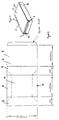
- a package 2 comprising, in this case, a tray 4 shown mostly in dotted lines for illustrative purposes within an erected carton blank 6.
- the tray is provided to carry foodstuffs and typically foodstuffs which are either pre-cooked or are "ready to cook” meals.
- the blank comprises a front face 8, rear face 10 and two side walls 12, 14 which when erected are held in parallel as shown in Figure 1.
- the package is formed by erecting the blank to the form shown in figure 1, moving the tray into the blank to the position shown in Figure 1 and then folding inwardly, location means 16, 18 provided at each of the end openings 20, 22 of the package.
- the location means are folded inwardly such that they act to retain the tray within the blank thereby forming the package and allowing the same to subsequently be put on display for retail purposes and also, provide added rigidity to the package by maintaining the side walls in a substantially parallel relationship regardless of the shape of the tray itself.
- This therefore overcomes the need for the blank to have side walls of a similar shape to the side walls of the tray as is the case with conventional sleeve arrangements and hence avoids the need for more than four crease lines to be provided which, in turn, allows substantially conventional forming machinery to be used with minor adjustment rather than completely new machinery to be used and without the need for additional board material to be utilised
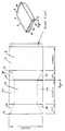
- FIG. 3 and 4 The embodiment shown in Figures 3 and 4 is similar to that of Figures 1 and 2 and, where appropriate, the same reference numerals are used.
- the main difference however is that in this case the location means at each of the openings differ inasmuch that there is provided a main flap 24 which is folded inwardly and then two side flaps 26, 28 are folded inwardly and in this case glued to the main flap to form the location means.
- This arrangement has the added advantage that they provide a degree of tamper evidence to the package inasmuch that the location means are formed so that the tray cannot be removed from the package without the glue tabs 26, 28 being opened. It is envisaged that this feature will be of importance to some retailers of packages of this type.
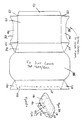
- each sleeve comprises a top surface 108, a base 110, side walls 112 and 114 and two open ends 116, 118.
- a first flap 120 depending from the base and two side flaps 122, 124 depending from the side walls which allow the partial closure of each of the openings.
- the sleeves can be provided in a number of different embodiments and the sleeve embodiment 106 is now described in greater detail.
- Figures 6A and 6B illustrate the sleeve 106 with Figure 6A illustrating the sleeve blank and Figure 6B illustrating a retail package formed in accordance with this embodiment.
- Figure 6A illustrates a sleeve used to form a blank with a location flap 116 at each open end 129 of the sleeve.
- the blank is also provided with a glue flap 131 provided to be glued to the side wall in the area 128 indicated by broken lines and thus, when formed, the sleeve can be provided in a flattened package form but then erected for the insertion of the tray at the time of packaging.
- a typical form of tray 133 which is to be inserted in this particular embodiment of sleeve is shown in broken lines in Figure 6B and comprises inwardly sloping side walls 130 which slope inwardly from a top surface 132 to the base 134. At the top surface are provided lugs 136, 138 which are provided for gripping the tray when in use and the top surface 108 of the sleeve is formed so as to extend beyond the lugs as shown.
- the tray in this form has curved side walls and the free edges of the location flaps 116 at each of the ports 129, are formed with shaped edges 135, as shown in Figure 6A, to match the shape of the tray side walls to contact same and exert a retaining action on the side walls to maintain the tray within the sleeve to hence form the retail pack of the invention.
- the edges of the top surface extend beyond the respective edges of the base and this is a significant part of the invention.
- the top surface 108 bows inwardly and if the top surface of the tray snags with this so the same cannot be introduced into the sleeve.
- Figure 7B illustrates a solution to this problem wherein the tray 133 is introduced towards the erected sleeve 106 as indicated by arrow 144.
- the plane defined by the transfer plate 146 which supports the tray as it is moved along towards the sleeve is on a lower plane than the lower surface 148 of the sleeve. This lower plane is maintained until the front end 150 of the tray reaches the position as indicated by broken lines 152 in which the same has entered the sleeve beyond the edge of the top surface but has not yet reached the edge 160 of the base 110.
- the transfer plate is shaped at section 161 to move the tray 133 upwardly thereby causing the front edge of the tray 150 to exert a lifting action as it moves to the position 156 shown by broken lines and hence supports the top surface and removes any bowing of the top surface 108 of the sleeve.
- the sleeve can then be introduced effectively and efficiently into the cavity of the sleeve and the gluing operation performed on the locating and securing flaps 116, 122, 124 to form the partial closing of the open ends of the sleeve as indicated in Figure 5.
- the invention provides several key advantages, namely, minimal board usage for the formation of the blanks and no additional board material usage in comparison with conventional sleeves.
- the package can be tamper evident without any additional board being used and there is no raw edge of carton board across any of the front, rear or side faces.
- the tolerances of the tray and carton do not need to be so tight as with the sleeve and tray arrangements and the machinery is adhesive free on the tucking version.
- the package has its own integrity and will hold square with odd shaped products.
Landscapes
- Engineering & Computer Science (AREA)
- Mechanical Engineering (AREA)
- Cartons (AREA)
- Packages (AREA)
Applications Claiming Priority (2)
| Application Number | Priority Date | Filing Date | Title |
|---|---|---|---|
| GB0028830 | 2000-11-25 | ||
| GBGB0028830.8A GB0028830D0 (en) | 2000-11-25 | 2000-11-25 | Package and machinery for forming same |
Publications (2)
| Publication Number | Publication Date |
|---|---|
| EP1209096A2 true EP1209096A2 (de) | 2002-05-29 |
| EP1209096A3 EP1209096A3 (de) | 2003-05-14 |
Family
ID=9903911
Family Applications (1)
| Application Number | Title | Priority Date | Filing Date |
|---|---|---|---|
| EP01309087A Withdrawn EP1209096A3 (de) | 2000-11-25 | 2001-10-26 | Verpackung und Maschine zum Formen derselben |
Country Status (2)
| Country | Link |
|---|---|
| EP (1) | EP1209096A3 (de) |
| GB (1) | GB0028830D0 (de) |
Cited By (1)
| Publication number | Priority date | Publication date | Assignee | Title |
|---|---|---|---|---|
| WO2007010434A1 (en) * | 2005-07-20 | 2007-01-25 | Nxp B.V. | Method and synchronizer for fine ofdm symbol synchronization and method/receiver for the reception of ofdm symbols |
Family Cites Families (5)
| Publication number | Priority date | Publication date | Assignee | Title |
|---|---|---|---|---|
| US3618848A (en) * | 1969-11-17 | 1971-11-09 | American Can Co | Paperboard sleeve for trays |
| GB1380240A (en) * | 1971-01-05 | 1975-01-08 | Boxfoldia Ltd | Packaging sleeve and blank therefor |
| GB8913877D0 (en) * | 1989-06-16 | 1989-08-02 | Freemantle Arthur J | Sleeving machine |
| US5481854A (en) * | 1993-09-24 | 1996-01-09 | Carter Control Systems, Inc. | Method of and apparatus for inserting trays of articles into sleeves |
| GB9910029D0 (en) * | 1999-05-01 | 1999-06-30 | Dart Machinery Group Limited | Packaging |
-
2000
- 2000-11-25 GB GBGB0028830.8A patent/GB0028830D0/en not_active Ceased
-
2001
- 2001-10-26 EP EP01309087A patent/EP1209096A3/de not_active Withdrawn
Cited By (1)
| Publication number | Priority date | Publication date | Assignee | Title |
|---|---|---|---|---|
| WO2007010434A1 (en) * | 2005-07-20 | 2007-01-25 | Nxp B.V. | Method and synchronizer for fine ofdm symbol synchronization and method/receiver for the reception of ofdm symbols |
Also Published As
| Publication number | Publication date |
|---|---|
| GB0028830D0 (en) | 2001-01-10 |
| EP1209096A3 (de) | 2003-05-14 |
Similar Documents
| Publication | Publication Date | Title |
|---|---|---|
| US6170740B1 (en) | Oval folding carton with automatic closing bottom | |
| US5806683A (en) | Wrapped package and method using molded fiber inner structure | |
| US6386369B2 (en) | Shipper and display carton | |
| US9783334B2 (en) | Shipping and display container | |
| JP4837051B2 (ja) | 平らなブランクカートン | |
| US5533667A (en) | Separable modular containers | |
| US20130056527A1 (en) | Folding-box insert, and folding box for a folding-box insert | |
| EP1380512B1 (de) | Faltschachtel mit Tasche für Beipackzettel und Zuschnitt dafür | |
| US4629069A (en) | Modular display package | |
| US2795365A (en) | Carton for cylindrical objects and blank for forming a plurality of said cartons | |
| JPH0749305B2 (ja) | ロツキングフラツプ接続によるラツプ・アラウンドカートン | |
| US20090057384A1 (en) | Carton for dispensing products and method of using the same | |
| US6152359A (en) | Oval folding carton with automatic closing | |
| US4903892A (en) | Fragile article carton | |
| MXPA03010048A (es) | Cajon envolvente de cuatro esquinas. | |
| US4627536A (en) | Modular display package | |
| GB2198709A (en) | Carton-forming blank | |
| US6651873B2 (en) | Container with bag cuff grab means | |
| EP0671332A1 (de) | Ineinandersetzbare Trag-Verpackung aus Pappe | |
| EP1209096A2 (de) | Verpackung und Maschine zum Formen derselben | |
| US6481618B2 (en) | Divisible transport box | |
| GB2264287A (en) | A container | |
| GB2205083A (en) | Boxes formed from blanks | |
| GB2027413A (en) | A packaging method and carton | |
| MXPA03001284A (es) | Caja de carton y lienzo. |
Legal Events
| Date | Code | Title | Description |
|---|---|---|---|
| PUAI | Public reference made under article 153(3) epc to a published international application that has entered the european phase |
Free format text: ORIGINAL CODE: 0009012 |
|
| AK | Designated contracting states |
Kind code of ref document: A2 Designated state(s): AT BE CH CY DE DK ES FI FR GB GR IE IT LI LU MC NL PT SE TR |
|
| AX | Request for extension of the european patent |
Free format text: AL;LT;LV;MK;RO;SI |
|
| PUAL | Search report despatched |
Free format text: ORIGINAL CODE: 0009013 |
|
| AK | Designated contracting states |
Designated state(s): AT BE CH CY DE DK ES FI FR GB GR IE IT LI LU MC NL PT SE TR |
|
| AX | Request for extension of the european patent |
Extension state: AL LT LV MK RO SI |
|
| RIC1 | Information provided on ipc code assigned before grant |
Ipc: 7B 65B 43/42 B Ipc: 7B 65D 77/04 B Ipc: 7B 65D 77/00 A |
|
| 17P | Request for examination filed |
Effective date: 20031113 |
|
| AKX | Designation fees paid |
Designated state(s): AT BE CH CY DE DK ES FI FR GB GR IE IT LI LU MC NL PT SE TR |
|
| 17Q | First examination report despatched |
Effective date: 20040202 |
|
| 17Q | First examination report despatched |
Effective date: 20040202 |
|
| STAA | Information on the status of an ep patent application or granted ep patent |
Free format text: STATUS: THE APPLICATION IS DEEMED TO BE WITHDRAWN |
|
| 18D | Application deemed to be withdrawn |
Effective date: 20080501 |