EP1209103B1 - Machine pour l'orientation et l'alignement de récipiénts de tailles differentes - Google Patents
Machine pour l'orientation et l'alignement de récipiénts de tailles differentes Download PDFInfo
- Publication number
- EP1209103B1 EP1209103B1 EP00830760A EP00830760A EP1209103B1 EP 1209103 B1 EP1209103 B1 EP 1209103B1 EP 00830760 A EP00830760 A EP 00830760A EP 00830760 A EP00830760 A EP 00830760A EP 1209103 B1 EP1209103 B1 EP 1209103B1
- Authority
- EP
- European Patent Office
- Prior art keywords
- gear
- rotating drum
- drum
- motor
- engaging
- Prior art date
- Legal status (The legal status is an assumption and is not a legal conclusion. Google has not performed a legal analysis and makes no representation as to the accuracy of the status listed.)
- Expired - Lifetime
Links
- 230000033001 locomotion Effects 0.000 claims description 18
- 230000009467 reduction Effects 0.000 claims description 6
- 230000005540 biological transmission Effects 0.000 claims description 3
- 210000003739 neck Anatomy 0.000 description 3
- 230000001105 regulatory effect Effects 0.000 description 3
- 230000008901 benefit Effects 0.000 description 2
- 230000009471 action Effects 0.000 description 1
- 238000000071 blow moulding Methods 0.000 description 1
- 230000008859 change Effects 0.000 description 1
- 238000007689 inspection Methods 0.000 description 1
- 238000000034 method Methods 0.000 description 1
- 238000000465 moulding Methods 0.000 description 1
- 230000004044 response Effects 0.000 description 1
- 230000032258 transport Effects 0.000 description 1
Images


Classifications
-
- B—PERFORMING OPERATIONS; TRANSPORTING
- B65—CONVEYING; PACKING; STORING; HANDLING THIN OR FILAMENTARY MATERIAL
- B65G—TRANSPORT OR STORAGE DEVICES, e.g. CONVEYORS FOR LOADING OR TIPPING, SHOP CONVEYOR SYSTEMS OR PNEUMATIC TUBE CONVEYORS
- B65G47/00—Article or material-handling devices associated with conveyors; Methods employing such devices
- B65G47/02—Devices for feeding articles or materials to conveyors
- B65G47/04—Devices for feeding articles or materials to conveyors for feeding articles
- B65G47/12—Devices for feeding articles or materials to conveyors for feeding articles from disorderly-arranged article piles or from loose assemblages of articles
- B65G47/14—Devices for feeding articles or materials to conveyors for feeding articles from disorderly-arranged article piles or from loose assemblages of articles arranging or orientating the articles by mechanical or pneumatic means during feeding
- B65G47/1407—Devices for feeding articles or materials to conveyors for feeding articles from disorderly-arranged article piles or from loose assemblages of articles arranging or orientating the articles by mechanical or pneumatic means during feeding the articles being fed from a container, e.g. a bowl
- B65G47/1442—Devices for feeding articles or materials to conveyors for feeding articles from disorderly-arranged article piles or from loose assemblages of articles arranging or orientating the articles by mechanical or pneumatic means during feeding the articles being fed from a container, e.g. a bowl by means of movement of the bottom or a part of the wall of the container
- B65G47/1457—Rotating movement in the plane of the rotating part
-
- B—PERFORMING OPERATIONS; TRANSPORTING
- B65—CONVEYING; PACKING; STORING; HANDLING THIN OR FILAMENTARY MATERIAL
- B65G—TRANSPORT OR STORAGE DEVICES, e.g. CONVEYORS FOR LOADING OR TIPPING, SHOP CONVEYOR SYSTEMS OR PNEUMATIC TUBE CONVEYORS
- B65G47/00—Article or material-handling devices associated with conveyors; Methods employing such devices
- B65G47/22—Devices influencing the relative position or the attitude of articles during transit by conveyors
- B65G47/24—Devices influencing the relative position or the attitude of articles during transit by conveyors orientating the articles
-
- B—PERFORMING OPERATIONS; TRANSPORTING
- B65—CONVEYING; PACKING; STORING; HANDLING THIN OR FILAMENTARY MATERIAL
- B65G—TRANSPORT OR STORAGE DEVICES, e.g. CONVEYORS FOR LOADING OR TIPPING, SHOP CONVEYOR SYSTEMS OR PNEUMATIC TUBE CONVEYORS
- B65G2201/00—Indexing codes relating to handling devices, e.g. conveyors, characterised by the type of product or load being conveyed or handled
- B65G2201/02—Articles
- B65G2201/0235—Containers
- B65G2201/0244—Bottles
Definitions
- the present invention applies to a machine for orienting and aligning plastic containers of varying size, referred to in technical jargon simply as "unscramblers”.
- These unscramblers are designed to place the containers, fed in bulk from blow-moulding and moulding machines, in a vertical attitude and to arrange them in a straight line for transportation to filling machines other machines, such as blow-moulders, rinsers and inspection units.
- unscrambler There are several types of unscrambler which are generally classified according to the method used to pick up each individual container and then position it in the desired manner.
- All unscramblers are equipped with a rotating drum which acts as a hopper, receiving the containers conveyed in bulk; some unscramblers are equipped with a drum which rotates around a vertical axis whose base is constructed in the form of a fixed cone; this allows the containers to roll and slide more easily towards the sides of the rotating drum which have blades or bars designed to push the containers along helical tracks extending from the base of the drum up to the upper rim.
- the top of the rotating drum includes a plurality of support pads of a size capable of accommodating a container up to a maximum size.
- a fixed drum is mounted externally at a certain distance from the rotating drum which, together with the first, creates an annular chamber; a fixed annular ledge along which the containers slide is mounted at the top of the chamber.
- the annular ledge forms the base of the pads and has one or more breaks in it to allow the containers to drop, neck upwards by operation of a well-known selector device.
- a plurality of funnel-shaped chutes connected to the rotating drum, is mounted underneath the annular ledge; these chutes direct the containers onto a plurality of tracks formed by radial walls connected to a second rotating drum mounted externally and coaxially below the first drum which constitutes the bulk loading hopper.
- EP-A-0540477 discloses another type of unscrambler, in which elevators composed of support pads on which the containers can be placed are mounted inside the first internal upper rotating drum.
- the elevators are driven by arms arranged radially around the drum and rotably fixed thereto. One end of the arms slides along the profile of a cam, appropriately shaped to allow the elevators to travel at least one forward and return stroke between the base and top of the drum, for each rotation of the drum.
- a fixed drum is mounted externally at a certain distance from the internal upper rotating drum; the fixed drum has an annular sliding ledge for the containers mounted underneath which constitutes the base of a plurality of support pads connected to the first rotating drum.
- the annular ledge has one or more breaks in it to allow the containers to drop, neck upwards, into a plurality of funnel-shaped hoppers connected to the external wall of the first rotating drum.
- This type of unscrambler also features a second rotating drum mounted externally and coaxially below the first drum which constitutes the bulk loading hopper.
- the second drum includes a plurality of chutes which represent an extension of the chutes connected to the loading hopper drum.
- the number of chutes mounted on the rotating drum is significantly higher than the number of tracks mounted on the loading hopper, with the aim of increasing the output of the machine.
- the rotation speed of the second rotating drum must clearly differ from the rotating speed of the first loading drum.
- the rotation speed of the first internal upper drum cannot be varied with respect to that of the second external lower drum.
- the rotation speed cannot be adapted to the size of the container, which is particularly important in the case of bottles available in a wide range of sizes.
- the rotation speed cannot be regulated in order to synchronise the two drums.
- the containers may tip over and bump into each other or against the walls of the chutes, particularly when being transferred from the chutes connected to the first internal upper drum to those connected to the second external lower drum.
- the ability to regulate the speed and to change the support pads and funnel-shaped hoppers, or chutes is particularly important when the machine is designed to handle bottles of different sizes.
- connection gears in the drive unit have to be changed in the event of a size changeover, wasting a great deal of time and reducing the productivity of the machine.
- the aim of the present invention is to eliminate the above-mentioned problems, creating a machine for orienting and aligning plastic containers of varying size which adapts the rotation speed of the moving elements to changes in the size of the containers, particularly in the case of bottles.
- Another aim of the present invention is to prevent the containers from tipping over or bumping into each other or against the walls of the chutes, particularly when being transferred from the rotating hopper to the drum rotating coaxially with it.
- a great advantage of the unscrambler according to one embodiment of the present invention is the ability to rotate the second drum by means of a second drive unit mechanically independent of the first unit.
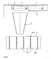
- the numeral 1 denotes a first rotating drum forming part of a machine for orienting and aligning plastic containers of varying size.
- the first drum is rotated by a first drive unit 2.
- This first drive unit 2 comprises, as illustrated in figure 1 , a first motor 2a which drives a first driving gear 2b engaging with a first driven gear 2c connected to the first drum 1.
- the containers are transferred from the base of the conical structure 3 and the first drum 1 to the top of the first drum by operation of means designed to convey the containers.
- Said conveying means are well-known and therefore not illustrated, and may include, for example, a plurality of blades connected to the first drum 1, designed to push the containers 4 along a helical track, or a plurality of elevators rotating with the first drum 1 and translatable between the base of the conical structure 3 and the top of the first drum 1.
- Support pads or trays 5 are mounted at the top of the first drum 1, on the external wall of the first drum and arranged tangentially along the upper circumference.
- the pads 5 are at least as wide as the height of the container 4 in order to accommodate the container in horizontal attitude, as illustrated at the top of figure 1 .
- the pads 5 also include means for turning over the containers 4, causing the containers to rotate substantially by 90° with their necks pointing upwards at all times. These turning means are well known and therefore not illustrated in the figure.
- the base of the pads 5 is composed of a fixed annular ledge 6 connected to a fixed drum 7.
- the fixed drum forms the external casing of the unscrambler and is mounted at an appropriate distance from the first drum 1 in order to create an annular chamber between the fixed drum 7 and the first drum.
- the annular ledge 6 includes a number of breaks, as illustrated in figure 2 , which allow the container 4 to drop, in a vertical attitude, below the pads 5.
- Figure 2 illustrates the movement of the container 4 from the position in which it rests on the annular ledge 6, indicated by the dotted line, to the position in which the container 4 no longer rests on the ledge, indicated by the continuous line.
- the first drum 1 also comprises a first set of chutes 8, mounted on the external wall of the first drum.
- This first chutes 8 are funnel-shaped for receiving the containers positioned in a substantially horizontal attitude while they are being turned over by the pads and placed in a vertical attitude, and then conveyed out of the unscrambler.
- a second rotating drum 9 mounted underneath the first set of chutes 8 rotates coaxially with the first drum 1 and is equipped with a second set of chutes 10.
- second chutes 10 are mounted below the first chutes 8 and form a single track, the output section of the first chutes 8 being aligned with the input section of the second chutes 10, as illustrated in figure 2 .
- the second chutes 10 may consist of a plurality of radial walls 10a.
- the number of chutes 10 is significantly higher than the number of chutes 8.
- the first drum 1 and the second drum 9 are driven at different speeds with different ratios.
- the second drum 9 is conveniently rotated by a second drive unit 11 mechanically independent of the first unit 2.
- the second drive unit 11 is composed of a second motor 11a which drives a second driving gear 11b engaging with a second driven gear 11c connected to the second drum 9.
- the second motor 11 a can conveniently be either a brushless motor or a stepping motor, thereby allowing the rotation speed of the second drum 9 to be regulated and therefore adapted to different sized containers, particularly in the case of bottles .
- the first drive unit 2 also comprises a brushless motor 2a in order to regulate the speed of the first drum in relation to that of the second drum, or to regulate the speed of both.
- Another convenient feature is the inclusion of an angular position detector in the first drive unit 2, designed to regulate the rotation of the second drum 9 by varying the rotation speed of the second motor 11a.
- the ability to synchronise the rotation speed of the two drums is particularly advantageous since the containers can be transferred, as they drop from the first chutes 8 into the second chutes 10, along a single track, thereby preventing them from bumping against the sides of the second chutes and tipping over.
- the bottle can drop gradually and thereby avoid tipping over which could jam the machine. By preventing the bottle from tipping over, it can also be transported through the machine in a considerably shorter period.
- the upper portion of the radial walls 10a are rounded to help the bottles drop gradually and thereby create a channelled chute 10b.
- the second drive unit 11 also drives a conveyor 12 which transports the containers 4 off the machine, picking them up from the bottom of the second set of chutes 10.
- the machine according to the present invention may include a motor 20 which directly rotates either the first or second drum and means for transmitting movement to the other of the two drums, thereby allowing the two drums to be driven at different speeds with different ratios.
- the embodiments of the transmission means are illustrated in figures 3 to 7 .
- the mechanical motor timing device 27 conventionally comprises a phase correction shaft 27c which is connected through an electric clutch 30 and an angular driving gear 31, to the gear 25.
- the electric clutch 30 By operating the electric clutch 30, the synchronisation of the input shaft and output shaft in the timing device can be varied, thereby varying the synchronisation of the first drum 1 and the second drum 9.
- Figure 4 illustrates a simpler embodiment which is nevertheless similar to the embodiment of figure 3 , where the gear 25 and the angular driving gear 31 driving the shaft 27c through the clutch 30 are replaced with a brushless motor 32, or equivalent, keyed directly onto the phase correction shaft 27c.
- Figure 5 illustrates an embodiment in which a gear 33, engaged with a gear 34 which transmits movement to a gear 35, is keyed onto the shaft 21b.
- the gear 34 is keyed onto a shaft 36 which transmits movement through an electric clutch 37, to a gear 38 which in turn engages with a gear 39 keyed onto a shaft 40 connected through an electric clutch 41, to the gear 35.
- the above-mentioned system allows the speed of the first drum 1 to be varied, that is, by energising either one or other of the two electromagnetic clutches, the speed is regulated according to the ratio between the gears.
- the motor-driven gear 22 engages with a crown gear 23 which rotates the second drum 9 and a plate 50 which, by means of a support 51 secured to the plate, keeps a shaft 52 running idly; a gear 53 is keyed to one end of the shaft 52 and engages with a crown gear 54 connected to the fixed frame of the machine.
- a Maltese cross-type device 55 is keyed onto the other end of the shaft 52 and transmits its typical form of movement to the first drum.
- the embodiment illustrated in figure 7 comprises a differential gear 56 whose input shaft 57 is motor-driven by a conventional gear transmission whilst the two output shafts are fitted, on one side with an electric brake 58, and on the other, with an angular driving gear 59 which transmits movement to the first drum 1.
- the speed is varied and transmitted by the differential gear to the angular gear 59 and then to the drum 1.
- the electric brake 58 may also be replaced with a brushless motor or any hydraulic or mechanical actuator capable of varying the revolutions per minute.
- the speed of the first drum 1 is varied, but it is clear that the aforementioned systems can be applied to the rotating action of the second drum 9, varying the speed of the second drum in relation to that of the first which is left to rotate at a fixed, constant speed.
- the unscrambler according to the present invention offers a number of significant advantages.
- the functions of the machine can be adapted to the varying size of the container, particularly in the case of bottles.
- the speed of the second drum 9 in relation to that of the first drum 1 can also be controlled electronically, with the use of an encoder fitted on the first motor 2a to detect its angular position, thereby synchronising the containers 4 as they drop, given the absence of any break between the first and second sets of chutes.
- the rotation speeds can be programmed according to the size of the container being handled and the operator does not therefore need to make any adjustments to the machine in response to a size changeover.
Landscapes
- Engineering & Computer Science (AREA)
- Mechanical Engineering (AREA)
- Feeding Of Articles To Conveyors (AREA)
- Attitude Control For Articles On Conveyors (AREA)
Claims (11)
- Machine pour l'orientation et l'alignement de récipients en plastique (4) de tailles différentes comprenant :- un premier tambour rotatif (1) ;- des moyens pour faire passer les récipients en plastique (4) du bas d'une structure conique fixe (3) montée à l'intérieur du premier tambour rotatif (1) en haut du premier tambour rotatif (1) ;- un premier ensemble de goulottes d'amenée (8) ancrées à la paroi extérieure du premier tambour rotatif (1) pour recevoir lesdits récipients (4) ;- un deuxième tambour (9) tournant coaxialement avec le premier tambour rotatif (1) et muni d'un deuxième ensemble de goulottes d'amenée (10) installées sous le premier ensemble de goulottes d'amenée (8) pour recevoir les récipients en plastique (4) à la verticale, dans laquelle
le premier et le deuxième tambours rotatifs (1, 9) sont commandés par un moteur à des vitesses différentes, caractérisée en ce que le premier tambour rotatif (1) est actionné par une première unité d'entraînement (2) et que le deuxième tambour rotatif (9) est actionné par une deuxième unité d'entraînement (11) mécaniquement indépendante de la première unité d'entraînement (2), permettant ainsi de varier le rapport des vitesses. - Machine selon la revendication 1, dans laquelle la deuxième unité d'entraînement (11) comprend soit un moteur pas à pas soit un moteur sans balais (11a) .
- Machine selon la revendication 1, dans laquelle la première unité d'entraînement (2) comprend soit un moteur pas à pas soit un moteur sans balais (2a).
- Machine selon l'une quelconque des revendications précédentes, dans laquelle la première unité d'entraînement (2) comprend un capteur de position angulaire qui règle la rotation du deuxième tambour (9).
- Machine pour l'orientation et l'alignement de récipients en plastique (4) de tailles différentes comprenant :- un premier tambour rotatif (1) ;- des moyens pour faire passer les récipients en plastique (4) du bas d'une structure conique fixe (3) montée à l'intérieur du premier tambour rotatif (1) en haut du premier tambour rotatif (1) ;- un premier ensemble de goulottes d'amenée (8) ancrées à la paroi extérieure du premier tambour rotatif (1) pour recevoir lesdits récipients en plastique (4) ;- un deuxième tambour (9) tournant coaxialement avec le premier tambour rotatif (1) et muni d'un deuxième ensemble de goulottes d'amenée (10) installées sous le premier ensemble de goulottes d'amenée (8) pour recevoir les récipients en plastique (4) à la verticale, où le premier et le deuxième tambours rotatifs (1, 9) sont commandés par un moteur à des vitesses différentes,caractérisée en ce que soit le premier soit le deuxième tambour rotatif (1, 9) est directement actionné par un moteur (20), et que l'autre tambour rotatif, soit le premier soit le deuxième (1, 9), est actionné par le moteur (20) par des moyens mécaniques, électriques ou électromagnétiques pour transmettre le mouvement qui permet de varier le rapport des vitesses.
- Machine selon la revendication 5, dans laquelle lesdits moyens de transmission du mouvement comprennent un mécanisme réducteur (21) avec deux arbres de prise de mouvement (21a, 21b) monté sur le moteur (20), une roue (22) calée sur un arbre de prise de mouvement (21a) engageant une roue menée (23) connectée au deuxième tambour rotatif (9), une roue (24) calée sur l'autre arbre de prise de mouvement (21b) engageant une roue (25) transmettant le mouvement à une autre roue (26) calée sur l'arbre d'entraînement (27a) d'un synchroniseur mécanique du moteur (27), et une roue (28) calée sur l'arbre de prise de mouvement (27b) du synchroniseur (27) engageant une roue plate (29) connectée au premier tambour rotatif (1).
- Machine selon la revendication 6, dans laquelle le synchroniseur mécanique (27) comprend un arbre correcteur des phases (27c) connecté par un embrayage électrique (30) et un engrenage angulaire (31) à la roue (25).
- Machine selon la revendication 5, dans laquelle lesdits moyens de transmission du mouvement comprennent un mécanisme réducteur (21) avec deux arbres de prise de mouvement (21a, 21b) monté sur le moteur (20), une roue (22) calée sur un arbre de prise de mouvement (21a) engageant une roue menée (23) connectée au deuxième tambour rotatif (9), une roue (24) calée sur l'autre arbre de prise de mouvement (21b) engageant une roue (26) calée sur un arbre d'entraînement (27a) d'un synchroniseur mécanique du moteur (27), ledit synchroniseur (27) comprenant un arbre correcteur des phases (27c) et un moteur sans balais (32) calé directement sur l'arbre correcteur des phases (27c), et une roue (28) calée sur l'arbre de prise de mouvement (27b) du synchroniseur (27) engageant une roue plate (29) connectée au premier tambour rotatif (1).
- Machine selon la revendication 5, dans laquelle lesdits moyens de transmission du mouvement comprennent un mécanisme réducteur (21) avec deux arbres de prise de mouvement (21a, 21b) monté sur le moteur (20), une roue (22) calée sur un arbre de prise de mouvement (21a) engageant une roue menée (23) connectée au deuxième tambour rotatif (9), et une première roue (33) calée sur l'autre arbre de prise de mouvement (21b) engageant une deuxième roue (34) transmettant le mouvement à une troisième roue (35), ladite deuxième roue (34) étant calée sur un arbre (36) transmettant le mouvement par un embrayage électrique (37) à une quatrième roue (38) engageant une roue plate (29) connectée au premier tambour rotatif (1), ladite quatrième roue (38) s'engageant avec une cinquième roue (39) calée sur un arbre (40) connecté par un embrayage électrique (41) à la troisième roue (35).
- Machine selon la revendication 5, dans laquelle lesdits moyens de transmission du mouvement comprennent un mécanisme réducteur (21) monté sur le moteur (20), une roue (22) calée sur un arbre de prise de mouvement (21a) du mécanisme réducteur (21) engageant une roue menée (23) connectée au deuxième tambour rotatif (9), un support (51) fixé à un plateau (50) sur le deuxième tambour rotatif (9), un arbre (52) tournant librement sur ledit support (51),
une roue (53) calée à une première extrémité dudit arbre (52) s'engageant avec une roue plate (54) connectée à un bâti fixe de la machine et un dispositif à croix de Malte (55) calé sur une deuxième extrémité de l'arbre (52) pour transmette son mouvement au premier tambour rotatif (1). - Machine selon la revendication 5, dans laquelle lesdits moyens de transmission du mouvement comprennent un mécanisme réducteur (21) avec deux arbres de prise de mouvement (21a, 21b) monté sur le moteur (20), une roue (22) calée sur un arbre de prise de mouvement (21a) engageant une roue menée (23) connectée au deuxième tambour rotatif (9), et une roue de différentiel (56) comprenant un arbre d'entraînement (57) et deux arbres de prise de mouvement, dans laquelle l'arbre d'entraînement (57) est motorisé au moyen d'une transmission par engrenages engageant l'autre arbre de prise de mouvement (21b), un arbre de prise de mouvement est équipé d'un frein électrique (58), et l'autre arbre de prise de mouvement est muni d'un engrenage angulaire (59) qui transmet le mouvement au premier tambour rotatif (1).
Priority Applications (3)
| Application Number | Priority Date | Filing Date | Title |
|---|---|---|---|
| DE60044461T DE60044461D1 (de) | 2000-11-17 | 2000-11-17 | Maschine zum Orientieren und Ausrichten von Kunststoffbehältern unterschiedlicher Grösse |
| EP00830760A EP1209103B1 (fr) | 2000-11-17 | 2000-11-17 | Machine pour l'orientation et l'alignement de récipiénts de tailles differentes |
| AT00830760T ATE469072T1 (de) | 2000-11-17 | 2000-11-17 | Maschine zum orientieren und ausrichten von kunststoffbehältern unterschiedlicher grösse |
Applications Claiming Priority (1)
| Application Number | Priority Date | Filing Date | Title |
|---|---|---|---|
| EP00830760A EP1209103B1 (fr) | 2000-11-17 | 2000-11-17 | Machine pour l'orientation et l'alignement de récipiénts de tailles differentes |
Publications (2)
| Publication Number | Publication Date |
|---|---|
| EP1209103A1 EP1209103A1 (fr) | 2002-05-29 |
| EP1209103B1 true EP1209103B1 (fr) | 2010-05-26 |
Family
ID=8175552
Family Applications (1)
| Application Number | Title | Priority Date | Filing Date |
|---|---|---|---|
| EP00830760A Expired - Lifetime EP1209103B1 (fr) | 2000-11-17 | 2000-11-17 | Machine pour l'orientation et l'alignement de récipiénts de tailles differentes |
Country Status (3)
| Country | Link |
|---|---|
| EP (1) | EP1209103B1 (fr) |
| AT (1) | ATE469072T1 (fr) |
| DE (1) | DE60044461D1 (fr) |
Families Citing this family (8)
| Publication number | Priority date | Publication date | Assignee | Title |
|---|---|---|---|---|
| ITPR20030006A1 (it) | 2003-02-06 | 2004-08-07 | Lanfranchi Srl | Macchina per orientare, raddrizzare ed allineare |
| ITPR20030013A1 (it) * | 2003-02-19 | 2004-08-20 | Lanfranchi Srl | Trasportatore a stella per alimentare o evacuare contenitori o bottiglie in plastica vuoti ad una macchina e macchina raddrizzatrice e allineatrice incorporante detto trasportatore a stella. |
| ITPR20030017A1 (it) * | 2003-03-12 | 2004-09-13 | Lanfranchi Srl | Macchina raddrizzatrice e allineatrice |
| ITPR20050001A1 (it) * | 2005-01-21 | 2006-07-22 | Lanfranchi Srl | Macchina e procedimento per ordinare ed allineare contenitori in plastica cumulati in maniera disordinata. |
| ITBO20110552A1 (it) * | 2011-09-27 | 2013-03-28 | Ima Life Srl | Dispositivo e metodo per prelevare ed immettere contenitori da e su una linea di convogliamento |
| WO2016103156A1 (fr) | 2014-12-22 | 2016-06-30 | Lanfranchi S.R.L. | Procédé pour déplacer des récipients et machine rotative pour orienter des récipients en vrac, qui met en œuvre ledit procédé |
| EP3237313A1 (fr) | 2014-12-22 | 2017-11-01 | Lanfranchi S.r.l. | Procédé pour déplacer des récipients sélectionnés ou alignés dans une machine d'orientation et appareil correspondant |
| ITUB20153928A1 (it) | 2015-09-28 | 2017-03-28 | Lanfranchi Srl | Metodo di movimentazione e trasferimento di contenitori allineati in una macchina ordinatrice ad una sottostante riempitrice e apparato cosi' realizzato. |
Family Cites Families (3)
| Publication number | Priority date | Publication date | Assignee | Title |
|---|---|---|---|---|
| US4825995A (en) | 1988-04-18 | 1989-05-02 | John R. Nalbach Engineering Co., Inc. | Article orienting apparatus |
| IT1253395B (it) | 1991-10-28 | 1995-08-08 | Lino Lanfranchi | Perfezionamento in macchina orientatrice di contenitori. |
| IT1287097B1 (it) | 1996-11-12 | 1998-08-04 | Lanfranchi Autom Ind & C Snc | Macchina di alimentazione ordinata di bottiglie |
-
2000
- 2000-11-17 EP EP00830760A patent/EP1209103B1/fr not_active Expired - Lifetime
- 2000-11-17 AT AT00830760T patent/ATE469072T1/de not_active IP Right Cessation
- 2000-11-17 DE DE60044461T patent/DE60044461D1/de not_active Expired - Lifetime
Also Published As
| Publication number | Publication date |
|---|---|
| ATE469072T1 (de) | 2010-06-15 |
| EP1209103A1 (fr) | 2002-05-29 |
| DE60044461D1 (de) | 2010-07-08 |
Similar Documents
| Publication | Publication Date | Title |
|---|---|---|
| US8701865B2 (en) | Unscrambling machine for containers and relative process | |
| EP1209103B1 (fr) | Machine pour l'orientation et l'alignement de récipiénts de tailles differentes | |
| GB2231559A (en) | Product aligning device, particularly for supplying wrapping machines | |
| CN115676334B (zh) | 用于缓冲对象的设备和方法 | |
| JP2018108277A (ja) | 薬剤フィーダ | |
| US20080060912A1 (en) | Adjustable transfer unit for transferring upright and aligned articles from a first to a second conveyor | |
| US5158168A (en) | Container transfer device | |
| EP0486439B1 (fr) | Dispositif pour l'entraînement synchrone des moyens de remplissage et de manipulation de récipients dans les machines d'embouteillage | |
| US5823738A (en) | Method and unit for forming stacks of articles | |
| EP2501633B1 (fr) | Chargeur rotatif de lopins | |
| EP1760016B1 (fr) | Appareil et procede permettant de positionner des articles, comprenant plusieurs dechargements par cycle | |
| US4653674A (en) | Device for dispensing goods through annular dispensing port | |
| WO1999006281A1 (fr) | Appareil de transfert de produits et systeme comportant un tel appareil | |
| JP3522393B2 (ja) | 物品送り出し装置およびその方法 | |
| DE10121833A1 (de) | Transportanlage für Stückgut | |
| CN110816964A (zh) | 细小瓶子输送装置及工作方法 | |
| KR101216534B1 (ko) | 정제검사기용 정제 공급장치 | |
| CN215796795U (zh) | 一种超高速理瓶机 | |
| JP6775287B2 (ja) | 物品送出し装置および充填包装機構 | |
| US20190071256A1 (en) | Sorting device of bulk containers with automatic size change | |
| EP0348471A1 (fr) | Balance de verification en ligne droite | |
| US5316127A (en) | Apparatus for loading containers on a conveyor | |
| AU762668B2 (en) | Transfer mechanism | |
| CN115848742B (zh) | 一种多通道点数供料装置 | |
| JPS6037283Y2 (ja) | 円形容器供給装置 |
Legal Events
| Date | Code | Title | Description |
|---|---|---|---|
| PUAI | Public reference made under article 153(3) epc to a published international application that has entered the european phase |
Free format text: ORIGINAL CODE: 0009012 |
|
| AK | Designated contracting states |
Kind code of ref document: A1 Designated state(s): AT BE CH CY DE DK ES FI FR GB GR IE IT LI LU MC NL PT SE TR |
|
| AX | Request for extension of the european patent |
Free format text: AL;LT;LV;MK;RO;SI |
|
| 17P | Request for examination filed |
Effective date: 20021016 |
|
| AKX | Designation fees paid |
Designated state(s): AT BE CH CY DE DK ES FI FR GB GR IE IT LI LU MC NL PT SE TR |
|
| 17Q | First examination report despatched |
Effective date: 20060616 |
|
| R17C | First examination report despatched (corrected) |
Effective date: 20060616 |
|
| GRAP | Despatch of communication of intention to grant a patent |
Free format text: ORIGINAL CODE: EPIDOSNIGR1 |
|
| GRAS | Grant fee paid |
Free format text: ORIGINAL CODE: EPIDOSNIGR3 |
|
| GRAA | (expected) grant |
Free format text: ORIGINAL CODE: 0009210 |
|
| AK | Designated contracting states |
Kind code of ref document: B1 Designated state(s): AT BE CH CY DE DK ES FI FR GB GR IE IT LI LU MC NL PT SE TR |
|
| REG | Reference to a national code |
Ref country code: GB Ref legal event code: FG4D |
|
| REG | Reference to a national code |
Ref country code: CH Ref legal event code: EP |
|
| REG | Reference to a national code |
Ref country code: IE Ref legal event code: FG4D |
|
| REF | Corresponds to: |
Ref document number: 60044461 Country of ref document: DE Date of ref document: 20100708 Kind code of ref document: P |
|
| REG | Reference to a national code |
Ref country code: NL Ref legal event code: VDEP Effective date: 20100526 |
|
| PG25 | Lapsed in a contracting state [announced via postgrant information from national office to epo] |
Ref country code: SE Free format text: LAPSE BECAUSE OF FAILURE TO SUBMIT A TRANSLATION OF THE DESCRIPTION OR TO PAY THE FEE WITHIN THE PRESCRIBED TIME-LIMIT Effective date: 20100526 |
|
| PG25 | Lapsed in a contracting state [announced via postgrant information from national office to epo] |
Ref country code: AT Free format text: LAPSE BECAUSE OF FAILURE TO SUBMIT A TRANSLATION OF THE DESCRIPTION OR TO PAY THE FEE WITHIN THE PRESCRIBED TIME-LIMIT Effective date: 20100526 Ref country code: FI Free format text: LAPSE BECAUSE OF FAILURE TO SUBMIT A TRANSLATION OF THE DESCRIPTION OR TO PAY THE FEE WITHIN THE PRESCRIBED TIME-LIMIT Effective date: 20100526 |
|
| PG25 | Lapsed in a contracting state [announced via postgrant information from national office to epo] |
Ref country code: GR Free format text: LAPSE BECAUSE OF FAILURE TO SUBMIT A TRANSLATION OF THE DESCRIPTION OR TO PAY THE FEE WITHIN THE PRESCRIBED TIME-LIMIT Effective date: 20100827 Ref country code: CY Free format text: LAPSE BECAUSE OF FAILURE TO SUBMIT A TRANSLATION OF THE DESCRIPTION OR TO PAY THE FEE WITHIN THE PRESCRIBED TIME-LIMIT Effective date: 20100526 |
|
| PG25 | Lapsed in a contracting state [announced via postgrant information from national office to epo] |
Ref country code: DK Free format text: LAPSE BECAUSE OF FAILURE TO SUBMIT A TRANSLATION OF THE DESCRIPTION OR TO PAY THE FEE WITHIN THE PRESCRIBED TIME-LIMIT Effective date: 20100526 Ref country code: NL Free format text: LAPSE BECAUSE OF FAILURE TO SUBMIT A TRANSLATION OF THE DESCRIPTION OR TO PAY THE FEE WITHIN THE PRESCRIBED TIME-LIMIT Effective date: 20100526 Ref country code: PT Free format text: LAPSE BECAUSE OF FAILURE TO SUBMIT A TRANSLATION OF THE DESCRIPTION OR TO PAY THE FEE WITHIN THE PRESCRIBED TIME-LIMIT Effective date: 20100927 |
|
| PGFP | Annual fee paid to national office [announced via postgrant information from national office to epo] |
Ref country code: FR Payment date: 20101210 Year of fee payment: 11 |
|
| PG25 | Lapsed in a contracting state [announced via postgrant information from national office to epo] |
Ref country code: BE Free format text: LAPSE BECAUSE OF FAILURE TO SUBMIT A TRANSLATION OF THE DESCRIPTION OR TO PAY THE FEE WITHIN THE PRESCRIBED TIME-LIMIT Effective date: 20100526 |
|
| PLBE | No opposition filed within time limit |
Free format text: ORIGINAL CODE: 0009261 |
|
| STAA | Information on the status of an ep patent application or granted ep patent |
Free format text: STATUS: NO OPPOSITION FILED WITHIN TIME LIMIT |
|
| 26N | No opposition filed |
Effective date: 20110301 |
|
| PGFP | Annual fee paid to national office [announced via postgrant information from national office to epo] |
Ref country code: DE Payment date: 20110131 Year of fee payment: 11 |
|
| REG | Reference to a national code |
Ref country code: DE Ref legal event code: R097 Ref document number: 60044461 Country of ref document: DE Effective date: 20110228 |
|
| PG25 | Lapsed in a contracting state [announced via postgrant information from national office to epo] |
Ref country code: MC Free format text: LAPSE BECAUSE OF NON-PAYMENT OF DUE FEES Effective date: 20101130 |
|
| REG | Reference to a national code |
Ref country code: CH Ref legal event code: PL |
|
| GBPC | Gb: european patent ceased through non-payment of renewal fee |
Effective date: 20101117 |
|
| PG25 | Lapsed in a contracting state [announced via postgrant information from national office to epo] |
Ref country code: LI Free format text: LAPSE BECAUSE OF NON-PAYMENT OF DUE FEES Effective date: 20101130 Ref country code: CH Free format text: LAPSE BECAUSE OF NON-PAYMENT OF DUE FEES Effective date: 20101130 |
|
| PG25 | Lapsed in a contracting state [announced via postgrant information from national office to epo] |
Ref country code: IE Free format text: LAPSE BECAUSE OF NON-PAYMENT OF DUE FEES Effective date: 20101117 |
|
| PG25 | Lapsed in a contracting state [announced via postgrant information from national office to epo] |
Ref country code: GB Free format text: LAPSE BECAUSE OF NON-PAYMENT OF DUE FEES Effective date: 20101117 |
|
| REG | Reference to a national code |
Ref country code: FR Ref legal event code: ST Effective date: 20120731 |
|
| REG | Reference to a national code |
Ref country code: DE Ref legal event code: R119 Ref document number: 60044461 Country of ref document: DE Effective date: 20120601 |
|
| PG25 | Lapsed in a contracting state [announced via postgrant information from national office to epo] |
Ref country code: LU Free format text: LAPSE BECAUSE OF NON-PAYMENT OF DUE FEES Effective date: 20101117 |
|
| PG25 | Lapsed in a contracting state [announced via postgrant information from national office to epo] |
Ref country code: TR Free format text: LAPSE BECAUSE OF FAILURE TO SUBMIT A TRANSLATION OF THE DESCRIPTION OR TO PAY THE FEE WITHIN THE PRESCRIBED TIME-LIMIT Effective date: 20100526 |
|
| PG25 | Lapsed in a contracting state [announced via postgrant information from national office to epo] |
Ref country code: FR Free format text: LAPSE BECAUSE OF NON-PAYMENT OF DUE FEES Effective date: 20111130 |
|
| PGFP | Annual fee paid to national office [announced via postgrant information from national office to epo] |
Ref country code: IT Payment date: 20121130 Year of fee payment: 13 |
|
| PG25 | Lapsed in a contracting state [announced via postgrant information from national office to epo] |
Ref country code: DE Free format text: LAPSE BECAUSE OF NON-PAYMENT OF DUE FEES Effective date: 20120601 |
|
| PG25 | Lapsed in a contracting state [announced via postgrant information from national office to epo] |
Ref country code: ES Free format text: LAPSE BECAUSE OF FAILURE TO SUBMIT A TRANSLATION OF THE DESCRIPTION OR TO PAY THE FEE WITHIN THE PRESCRIBED TIME-LIMIT Effective date: 20100906 |
|
| PG25 | Lapsed in a contracting state [announced via postgrant information from national office to epo] |
Ref country code: IT Free format text: LAPSE BECAUSE OF NON-PAYMENT OF DUE FEES Effective date: 20131117 |