EP1209128A2 - Mécanisme de plongeur pour alimenter des paraisons en verre fondu - Google Patents
Mécanisme de plongeur pour alimenter des paraisons en verre fondu Download PDFInfo
- Publication number
- EP1209128A2 EP1209128A2 EP01127860A EP01127860A EP1209128A2 EP 1209128 A2 EP1209128 A2 EP 1209128A2 EP 01127860 A EP01127860 A EP 01127860A EP 01127860 A EP01127860 A EP 01127860A EP 1209128 A2 EP1209128 A2 EP 1209128A2
- Authority
- EP
- European Patent Office
- Prior art keywords
- slide
- unit
- guide
- axis
- molten glass
- Prior art date
- Legal status (The legal status is an assumption and is not a legal conclusion. Google has not performed a legal analysis and makes no representation as to the accuracy of the status listed.)
- Withdrawn
Links
Images
Classifications
-
- C—CHEMISTRY; METALLURGY
- C03—GLASS; MINERAL OR SLAG WOOL
- C03B—MANUFACTURE, SHAPING, OR SUPPLEMENTARY PROCESSES
- C03B7/00—Distributors for the molten glass; Means for taking-off charges of molten glass; Producing the gob, e.g. controlling the gob shape, weight or delivery tact
- C03B7/08—Feeder spouts, e.g. gob feeders
- C03B7/086—Plunger mechanisms
Definitions
- the present invention relates to a unit for forming molten glass beads.
- glass gobs are used, which are formed by first forming a molten glass bead, and then cutting the bead using a normally scissor-type cutting device.
- the molten glass bead is formed from a mass of molten glass using forming units, which normally comprise a container for the mass of molten glass; one or more vertical punches carried by a slide running along a vertical guide; and a slide actuating device for moving the punches back and forth cyclically through the mass of molten glass to force it gradually out through one or more openings formed in the bottom of the container and so form one or more glass beads.
- forming units which normally comprise a container for the mass of molten glass; one or more vertical punches carried by a slide running along a vertical guide; and a slide actuating device for moving the punches back and forth cyclically through the mass of molten glass to force it gradually out through one or more openings formed in the bottom of the container and so form one or more glass beads.
- the actuating device is mechanical, and comprises an electric rotary motor having an output shaft rotating about its axis; and a mechanical lever- or screw-nut screw-type transmission interposed between the output shaft of the motor and the slide to convert the rotary motion of the output shaft of the motor to translational back and forth motion of the slide.
- such devices are designed to minimize inertia and internal friction, so as to achieve as high an operating rate as possible with the minimum amount of energy, and to minimize slack between the parts in relative motion - particularly in the transmission connecting the rotary motor to the slide - so as to ensure precise movement of the punches and safeguard against positioning errors which, though negligible in a single extrusion cycle, must be taken into serious consideration when the punch movement is varied continuously to produce series of gobs differing in weight, shape and size.
- Known devices also comprise a large number of, at times, fairly complex component parts, and are relatively bulky, especially crosswise to the punches.
- a unit for forming a molten glass bead comprising a fixed supporting frame; a guide integral with said frame and having a substantially vertical axis; a slide fitted in axially-sliding manner to said guide and supporting at least one feed punch parallel to said axis; and actuating means for moving the slide cyclically in both directions along the guide; characterized in that said actuating means comprise a linear electric motor.
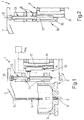
- Number 1 in Figure 1 indicates as a whole a forming unit forming part of a known glassware molding machine (not shown), and for forming a molten glass bead 2 from a mass of molten glass housed in a known container 3 forming part of unit 1 and connected to a fixed supporting structure 4 also forming part of unit 1.
- unit 1 also comprises a vertical punch 6, a top end portion of which is connected integrally to a supporting arm 7, and a bottom end portion of which extends inside container 3 and is coaxial with an opening 8 in container 3, through which glass bead 2 comes out.
- Arm 7 and, therefore, punch 6 are moved up and down cyclically by an actuating device 10 comprising a guide 11 integral with structure 4 and having a vertical axis 12 parallel to punch 6; and a slide 13 - in this case, defined by a cylindrical rod coaxial with axis 12 - which is fitted in axially-sliding manner to guide 11, and is fitted integrally with projecting arm 7.
- Slide 13 is moved along guide 11 by a linear electric motor 15, which is controlled by a central control unit 15a, extends alongside guide 11, and comprises a fixed member 16 extending parallel to and spaced transversely apart from axis 12; and a translating member 17 connected integrally and directly to, and translating in unison with, slide 13.
- translating member 17 extends beneath slide 13, along axis 12, and is aligned with slide 13 so as to translate together with slide 13 along axis 12.
- slide 13 comprises a hollow intermediate portion at least partly housing translating member 17 of motor 15.
- unit 1 described therefore has the advantage of being extremely straightforward in design and relatively cheap to both produce and maintain.
- actuating device 10 of punch 6 The reason for this substantially lies in the particular design of actuating device 10 of punch 6. That is, using a linear electric motor, as opposed to currently used rotary motors, provides, first of all, for eliminating the mechanical transmission interposed, in known actuating devices, between the output shaft of the rotary motor and the punch slide to convert the rotary motion of the output shaft of the motor to linear motion of the slide.
- unit 1 described therefore has very little inertia and substantially no slack, and so provides for an extremely high degree of efficiency and reliability.
- slide 13 is connected directly to translating member 17 of motor 15, as opposed to motion-converting devices, thus greatly reducing, with respect to known units, both inertia and slack, which, in known solutions, pose serious problems, especially when the punch movement is varied to cut different glass gobs off the bead.
- both guide 11 and slide 13 may be formed otherwise than as described by way of example; and changes may be made to both the location of translating member 17 with respect to slide 13, to reduce size as far as possible, and to the geometry of the members of linear motor 15.
Landscapes
- Chemical & Material Sciences (AREA)
- Engineering & Computer Science (AREA)
- Materials Engineering (AREA)
- Organic Chemistry (AREA)
- Transmission Devices (AREA)
- Reinforced Plastic Materials (AREA)
- Chemical Or Physical Treatment Of Fibers (AREA)
- Reciprocating Pumps (AREA)
Applications Claiming Priority (2)
| Application Number | Priority Date | Filing Date | Title |
|---|---|---|---|
| IT2000TO001105A IT1320844B1 (it) | 2000-11-24 | 2000-11-24 | Gruppo di formatura per la realizzazione di cordoni di vetro fuso. |
| ITTO001105 | 2000-11-24 |
Publications (2)
| Publication Number | Publication Date |
|---|---|
| EP1209128A2 true EP1209128A2 (fr) | 2002-05-29 |
| EP1209128A3 EP1209128A3 (fr) | 2002-07-10 |
Family
ID=11458243
Family Applications (1)
| Application Number | Title | Priority Date | Filing Date |
|---|---|---|---|
| EP01127860A Withdrawn EP1209128A3 (fr) | 2000-11-24 | 2001-11-22 | Mécanisme de plongeur pour alimenter des paraisons en verre fondu |
Country Status (3)
| Country | Link |
|---|---|
| US (1) | US20020062665A1 (fr) |
| EP (1) | EP1209128A3 (fr) |
| IT (1) | IT1320844B1 (fr) |
Cited By (1)
| Publication number | Priority date | Publication date | Assignee | Title |
|---|---|---|---|---|
| EP2163527A1 (fr) * | 2008-09-12 | 2010-03-17 | Waltec Maschinen GmbH | Dispositif d'alimentation de verre en fusion |
Family Cites Families (2)
| Publication number | Priority date | Publication date | Assignee | Title |
|---|---|---|---|---|
| US5440183A (en) * | 1991-07-12 | 1995-08-08 | Denne Developments, Ltd. | Electromagnetic apparatus for producing linear motion |
| GB2329381A (en) * | 1997-09-18 | 1999-03-24 | Bh F | Apparatus for extruding molten glass gobs |
-
2000
- 2000-11-24 IT IT2000TO001105A patent/IT1320844B1/it active
-
2001
- 2001-11-21 US US09/993,369 patent/US20020062665A1/en not_active Abandoned
- 2001-11-22 EP EP01127860A patent/EP1209128A3/fr not_active Withdrawn
Cited By (1)
| Publication number | Priority date | Publication date | Assignee | Title |
|---|---|---|---|---|
| EP2163527A1 (fr) * | 2008-09-12 | 2010-03-17 | Waltec Maschinen GmbH | Dispositif d'alimentation de verre en fusion |
Also Published As
| Publication number | Publication date |
|---|---|
| EP1209128A3 (fr) | 2002-07-10 |
| US20020062665A1 (en) | 2002-05-30 |
| ITTO20001105A0 (it) | 2000-11-24 |
| ITTO20001105A1 (it) | 2002-05-24 |
| IT1320844B1 (it) | 2003-12-10 |
Similar Documents
| Publication | Publication Date | Title |
|---|---|---|
| BR8906273A (pt) | Dispositivo para virar uma embalagem | |
| US8631926B2 (en) | Device for pushing glass objects onto a conveyor belt | |
| EP0164902A1 (fr) | Couper d'une façon rectiligne | |
| EP1209128A2 (fr) | Mécanisme de plongeur pour alimenter des paraisons en verre fondu | |
| EP0055096A2 (fr) | Cisaille | |
| CN212497816U (zh) | 吸取装置 | |
| EP0712812B1 (fr) | Appareil de coupe, en particulier pour paraisons en verre | |
| US11993049B2 (en) | Press machine | |
| EP1050514A1 (fr) | Mécanisme de poincon plongueur pour presser des paraisons en verre fondu dans le moule ébaucheur d'une machine I.S. de fabrication d'objets creux | |
| EP0490294B1 (fr) | Dispositif pour couper des gouttes de matériau d'extrusion, comme de verre fondu, pour le distributeur d'une machine de fabrication | |
| EP1591226A1 (fr) | Dispositif pour produire des récipients thermoplastiques avec un moteur pas à pas linéaire pour déplacer le porte-outil | |
| CN220164236U (zh) | 一种薄饼整理包装设备 | |
| CN218139497U (zh) | 一种隐形眼镜模具的剪切分拣设备 | |
| MXPA03003026A (es) | Maquina para articulos de vidrio. | |
| CN208761801U (zh) | 一种自动切丝带机 | |
| CA2234868C (fr) | Appareil de cisaillement de paraisons de verre avec un amortissement ameliore des chariots de cisailles | |
| EP0203740A1 (fr) | Coupe rectiligne avec came de ciseaux | |
| CN117644542B (zh) | 一种电路板裁切设备 | |
| CN112171749B (zh) | 易于更换刀具的模切装置 | |
| KR200164850Y1 (ko) | 반도체 패키지 리드프레임 가공장치 | |
| CN209665905U (zh) | 一种圆锯横切机 | |
| CN208099193U (zh) | 一种弹簧加工用切割机构 | |
| SU975383A1 (ru) | Манипул тор | |
| CN217474393U (zh) | 一种冲片加工系统的侧收料装置 | |
| CN220683719U (zh) | 一种板材推送设备的自动传感推送机构 |
Legal Events
| Date | Code | Title | Description |
|---|---|---|---|
| PUAI | Public reference made under article 153(3) epc to a published international application that has entered the european phase |
Free format text: ORIGINAL CODE: 0009012 |
|
| PUAL | Search report despatched |
Free format text: ORIGINAL CODE: 0009013 |
|
| AK | Designated contracting states |
Kind code of ref document: A2 Designated state(s): AT BE CH CY DE DK ES FI FR GB GR IE IT LI LU MC NL PT SE TR |
|
| AX | Request for extension of the european patent |
Free format text: AL;LT;LV;MK;RO;SI |
|
| AK | Designated contracting states |
Kind code of ref document: A3 Designated state(s): AT BE CH CY DE DK ES FI FR GB GR IE IT LI LU MC NL PT SE TR |
|
| AX | Request for extension of the european patent |
Free format text: AL;LT;LV;MK;RO;SI |
|
| AKX | Designation fees paid |
Designated state(s): AT BE CH CY DE DK ES FI FR GB GR IE IT LI LU MC NL PT SE TR |
|
| STAA | Information on the status of an ep patent application or granted ep patent |
Free format text: STATUS: THE APPLICATION IS DEEMED TO BE WITHDRAWN |
|
| 18D | Application deemed to be withdrawn |
Effective date: 20030111 |