EP1209547A2 - Procédé et dispositif pour réguler les paramètres de l'air présent dans des locaux au moyen d'une climatisation - Google Patents
Procédé et dispositif pour réguler les paramètres de l'air présent dans des locaux au moyen d'une climatisation Download PDFInfo
- Publication number
- EP1209547A2 EP1209547A2 EP01127375A EP01127375A EP1209547A2 EP 1209547 A2 EP1209547 A2 EP 1209547A2 EP 01127375 A EP01127375 A EP 01127375A EP 01127375 A EP01127375 A EP 01127375A EP 1209547 A2 EP1209547 A2 EP 1209547A2
- Authority
- EP
- European Patent Office
- Prior art keywords
- air
- determined
- rsoll
- optimal
- room
- Prior art date
- Legal status (The legal status is an assumption and is not a legal conclusion. Google has not performed a legal analysis and makes no representation as to the accuracy of the status listed.)
- Withdrawn
Links
- 238000000034 method Methods 0.000 title claims abstract description 125
- 238000011156 evaluation Methods 0.000 claims abstract description 14
- 230000001419 dependent effect Effects 0.000 claims abstract description 8
- 238000013461 design Methods 0.000 claims abstract description 4
- 239000013598 vector Substances 0.000 claims description 73
- 238000005457 optimization Methods 0.000 claims description 46
- 238000010586 diagram Methods 0.000 claims description 39
- 238000011084 recovery Methods 0.000 claims description 34
- 238000004378 air conditioning Methods 0.000 claims description 15
- 230000006978 adaptation Effects 0.000 claims description 8
- 230000004888 barrier function Effects 0.000 claims 1
- 238000009434 installation Methods 0.000 abstract 4
- 238000001816 cooling Methods 0.000 description 16
- 238000004364 calculation method Methods 0.000 description 15
- 238000010438 heat treatment Methods 0.000 description 9
- 230000001276 controlling effect Effects 0.000 description 4
- 230000000875 corresponding effect Effects 0.000 description 3
- 238000007791 dehumidification Methods 0.000 description 3
- 239000000203 mixture Substances 0.000 description 3
- 238000005265 energy consumption Methods 0.000 description 2
- 238000009472 formulation Methods 0.000 description 2
- 238000007689 inspection Methods 0.000 description 2
- 238000005259 measurement Methods 0.000 description 2
- 230000001172 regenerating effect Effects 0.000 description 2
- 210000002023 somite Anatomy 0.000 description 2
- 230000003321 amplification Effects 0.000 description 1
- 238000013528 artificial neural network Methods 0.000 description 1
- 230000001143 conditioned effect Effects 0.000 description 1
- 238000011217 control strategy Methods 0.000 description 1
- 230000002596 correlated effect Effects 0.000 description 1
- 125000004122 cyclic group Chemical group 0.000 description 1
- 238000011161 development Methods 0.000 description 1
- 230000018109 developmental process Effects 0.000 description 1
- 238000005516 engineering process Methods 0.000 description 1
- 238000011835 investigation Methods 0.000 description 1
- 239000000463 material Substances 0.000 description 1
- 238000010606 normalization Methods 0.000 description 1
- 238000003199 nucleic acid amplification method Methods 0.000 description 1
- 238000012545 processing Methods 0.000 description 1
- 230000001105 regulatory effect Effects 0.000 description 1
- 238000000926 separation method Methods 0.000 description 1
- 238000012546 transfer Methods 0.000 description 1
- 238000011144 upstream manufacturing Methods 0.000 description 1
- 239000002918 waste heat Substances 0.000 description 1
- XLYOFNOQVPJJNP-UHFFFAOYSA-N water Substances O XLYOFNOQVPJJNP-UHFFFAOYSA-N 0.000 description 1
Images





Classifications
-
- G—PHYSICS
- G05—CONTROLLING; REGULATING
- G05B—CONTROL OR REGULATING SYSTEMS IN GENERAL; FUNCTIONAL ELEMENTS OF SUCH SYSTEMS; MONITORING OR TESTING ARRANGEMENTS FOR SUCH SYSTEMS OR ELEMENTS
- G05B13/00—Adaptive control systems, i.e. systems automatically adjusting themselves to have a performance which is optimum according to some preassigned criterion
- G05B13/02—Adaptive control systems, i.e. systems automatically adjusting themselves to have a performance which is optimum according to some preassigned criterion electric
- G05B13/0205—Adaptive control systems, i.e. systems automatically adjusting themselves to have a performance which is optimum according to some preassigned criterion electric not using a model or a simulator of the controlled system
- G05B13/024—Adaptive control systems, i.e. systems automatically adjusting themselves to have a performance which is optimum according to some preassigned criterion electric not using a model or a simulator of the controlled system in which a parameter or coefficient is automatically adjusted to optimise the performance
-
- Y—GENERAL TAGGING OF NEW TECHNOLOGICAL DEVELOPMENTS; GENERAL TAGGING OF CROSS-SECTIONAL TECHNOLOGIES SPANNING OVER SEVERAL SECTIONS OF THE IPC; TECHNICAL SUBJECTS COVERED BY FORMER USPC CROSS-REFERENCE ART COLLECTIONS [XRACs] AND DIGESTS
- Y02—TECHNOLOGIES OR APPLICATIONS FOR MITIGATION OR ADAPTATION AGAINST CLIMATE CHANGE
- Y02B—CLIMATE CHANGE MITIGATION TECHNOLOGIES RELATED TO BUILDINGS, e.g. HOUSING, HOUSE APPLIANCES OR RELATED END-USER APPLICATIONS
- Y02B30/00—Energy efficient heating, ventilation or air conditioning [HVAC]
- Y02B30/56—Heat recovery units
Definitions
- the invention relates to a method and a device for controlling the air temperature and the air humidity in rooms by means of an air conditioning system with energy recovery, especially in a full air conditioner.
- the aim of an air conditioning system is to maintain specified air conditions with regard to the temperature and humidity of the room air in the rooms to be air conditioned. These specifications are specified in a tolerance zone according to DIN 1946 and correspond to the thermal comfort of the people in these rooms.
- the task of controlling and regulating an air conditioning system is to stabilize the room air condition in this comfort zone, although changing internal and external heat and / or moisture loads act on the room.
- Internal heat loads are waste heat from people, machines and systems or heat losses.
- Internal moisture loads result from the release of moisture from people, plants and systems or, if moisture is lost, from hygroscopic materials in the room.
- the external loads are characterized by the changing ambient climate, especially characterized by outside air temperature and humidity.
- An automation system fulfills this task in that the performance of the individual air treatment units is automatically adapted to the changing internal and external loads, the so-called disturbance variables. Since there are various possibilities for this, methods have to be developed that implement this control task with minimal effort. This effort is then assessed by a target function, the essential parameters of which are economic and / or ecological parameters (energy consumption, energy costs, operating costs, CO 2 emissions and others).
- EP 0 786 712 A2 describes two separate processes, the one determine the room air setpoints, and on the other hand practical control procedures propose for the performance adjustment of the air treatment units.
- the procedure described there for determining the room air setpoints is based in principle on controlling the limits of the tolerance zone.
- the procedure was won only heuristically, not as a result of optimizing a changeable Objective function. This means that variable evaluations such as specific operating costs can also be made of the individual air treatment units are not taken into account.
- the initial information for the process is the actual values of the indoor air conditions t R and x R and the outdoor air conditions AU (t AU , x AU ). These measurements form two points in a tx diagram, the connection of which marks the possible state changes for the mixing chamber or the energy recuperator by means of a straight section.
- the outputs of conventional controllers for the supply air temperature and supply air humidity are used to derive the temperature and humidity requirements. From this information and the system configuration, two direction vectors are determined, which, after multiplication with evaluation factors, are entered in the tx diagram with the supply air setpoint as the coordinate origin. These assessment factors can take into account the specific costs of the individual air treatment units.
- the method is now essentially based on the fact that the supply air setpoint and the assessed demand vectors are projected onto the straight line of the energy recovery and are added there vectorially. The result is a point on the straight line of the energy recovery, the normalization of which to the length of the straight line section leads to a control signal for the energy recovery. This signal is used for direct control of the energy recovery.
- a cascade control for the room air temperature and humidity unit controls the other units, while maintaining the specified room air setpoints.
- the method is based on the assumption that the output signals of the controllers for supply air temperature and humidity, which represent the temperature and humidity requirements, weighted with the specific costs, are a measure of the cost flows of the individual units.
- the slave controllers In order to approximate this, it is imperative that the slave controllers have an integral part in the two cascade regulations. If the master controller also receives an I component to avoid permanent control deviations, the stability reserve of the cascade is restricted. The slave controller must therefore still have a D component. However, this leads to undesirable amplifications of high-frequency interference signals.
- the controller outputs depend on the controller parameters and the adjustment ranges of the units. In particular, the different adjustment ranges of the units force the control vectors to be normalized, which can be problematic in the individual case. It is not possible to derive an exact reference to the real operating costs, and it is also not possible to estimate the error of this approximation.
- the invention is therefore based on the object, the disadvantages mentioned above eliminate and create a process that optimizes the control and regulation of air temperature and humidity in an air conditioning system - in particular Full air conditioning system - guaranteed, and which still on a conventional one programmable logic controller, especially a compact PLC, is executable.
- the determination of the optimal room air setpoints in the partial steps, or the optimal control signals is in each case by means of sequential one-dimensional Optimization process carried out.
- the determination of the optimal room air setpoints is based on at least one of the, preferably made on all border lines of the comfort zone; preferably the corner points of the border lines are included.
- the optimal control signals are determined on the route of the states of the Air treatment units between the outside air condition and the optimal exhaust air condition within the t-x diagram.
- Optimality is broken down into two steps: The determination of the optimal room air setpoints and the determination of optimal control signals for the air treatment units. This separation is achieved in that suitable values of the Start signals for the control of the air treatment units (including energy recovery) depending on the starting conditions (room load, outside air condition) be specified.
- the optimized target function values are obtained via both sub-steps calculated exactly in a t-x diagram.
- a first preferred embodiment of the method according to the invention is realized by thereby determining the target function values for both substeps takes place that starting from the air condition after mixing chamber or energy recovery the temperature or humidity difference between this state and the Supply air setpoint is formed.
- the supply air setpoint results from the exhaust air condition and the known space load. Based on the two differences, in the case of Humidification of the demand vectors for the temperature treatment and the moisture treatment by multiplying by the direction vectors for the air treatment operations receive. The temperature component of the moisture requirement vector becomes Temperature demand vector added. These are required vectors in a t-x diagram applied to the state point of energy recovery. Now the specific ones Enthalpies for the state after energy recovery and for the End points of the temperature demand vector and for the supply air setpoint are formed.
- a certain enthalpy contains temperature and humidity a certain point or location.
- the difference between the specific enthalpy after energy recovery and that at the end point of the temperature demand vector is the specific enthalpy for the heat treatment.
- the difference between the specific temperature at End point of the temperature demand vector and the specific enthalpy of the supply air setpoint equal to the specific enthalpy for humidification.
- This specific Enthalpies are now multiplied by the coefficients (e.g. cost factors), which ensure adaptation to the type of objective function and its absolute values added. This value, multiplied by the value initially assumed to be constant of the supply air flow after passing through a mathematical optimization process the optimized objective function value.
- a second preferred embodiment of the method according to the invention is realized by the values of the objective function for the solution of the two sub-steps can be determined by the need vectors described above in a t-x diagram be projected on a straight line that is orthogonal to that through the state point of the energy recovery isenthalpic. The amount The addition of these projections is a measure of the objective function value.
- the one-dimensional optimization process can be a simple one-dimensional search procedure, such as the procedure for the golden ratio.
- an optimal one is used Room air condition sought on the limits of the comfort area.
- the second Partial step is a one-dimensional search for the optimal value for the control signal for the energy recuperator along the straight line of all possible changes in state of the energy recuperator.
- a Zero energy area is defined depending on the space load. This area is characterized in that the supply air setpoint solely by using the energy recovery can be achieved. If the outside air condition is in this area, the controllers for a temperature and a humidity unit are deactivated to avoid unnecessary Avoid actions. If the outside air condition is outside the zero energy area, becomes a one-dimensional search for the optimal room air setpoint made along at least one of the boundaries of the comfort area. Preferably four of the boundaries are searched.
- a preferred embodiment of the method according to the invention in the treatment of the second substep is characterized in that starting from the optimal control signal determined in the first partial step for energy recovery through a one-dimensional optimization process, is preferably determined by a one-dimensional search.
- the search is on a straight line that shows all possible state changes in the t-x diagram for the energy recovery describes.
- the other air treatment units are made by Controllers whose setpoints are specified by the first sub-step.
- the method according to the invention is based on the various air treatment units as well as any unit row and operating mode applicable.
- the coefficient of the objective function is like this to all conceivable requirements for example operating costs, energy consumption but also environmentally relevant assessments customizable.
- the air conditioning system can be optimally controlled such procedures on a PLC or DDC station (programmable logic controller control systems; Controls for building automation) can be implemented.
- a device is used to carry out the method according to the invention, in which the method is preferably hardware-wise in several modules is mapped and executed programmatically. In two of the main ones Modules can determine the optimal room air setpoints (function 1) and direct control of the energy recovery (function 2) must be implemented.
- a preferred embodiment of the device consists of a first component in that, based on the measured outside air condition and the room load, the optimal room air setpoints and as setpoints for the master controller Temperature cascade control or a humidity cascade control output become.
- This block also determines binary enable messages for the slave controllers of these two cascades. With these release messages, the controllers in Dependency on the room air setpoints deactivated if unnecessary control actions should be avoided.
- the values for the room load i.e. Heat and moisture load are the difference between the setpoints for the master controller (room) and slave controller (Supply air) formed after treatment by h-x modules.
- the two sequential controllers of the cascades control the via corresponding sequences Air treatment units, air heaters, air coolers and humidifiers.
- a preferred one Embodiment of the device implemented in the second module in the fact that, based on the indoor air and supply air setpoints resulting from the setpoints of the slave controllers of the two cascades are obtained from the second module, the control signal for direct control energy recovery is spent.
- an air conditioning system should consist of the following units: Energy recovery and / or mixing chamber, preheater, cooler, humidifier and reheater.
- the method according to the invention is not based on this arrangement Air treatment units limited.
- the economic and / or ecological effort with which this task is implemented is evaluated by a suitable objective function G. Without restricting the general validity, it should be assumed that the best possible implementation is achieved when the target function, the parameters of which also describe economic and / or ecological burdens or costs, assumes a minimum.
- the task is solved so that starting from the formulation of a universal Objective function and finding a minimum the control problem exactly and is separated into two process steps without loss of optimality, which is solved serially on the one hand in the optimized determination of the indoor air conditions and on the other hand in the optimized control of the air treatment units.
- the method according to the invention is designed in such a way that it is separated into two partial steps without loss of optimality:
- the target function with respect to the room air setpoints R setpoint is optimized.
- the target function value with respect to the direct control signals u ij opt is then optimized with the optimized room air setpoints R soll opt .
- the determination of the optimized room air setpoints is dependent in particular on the size of the control signal for the mixing chamber or the energy recuperator.
- the method according to the invention addresses the problem in such a way that when the first sub-step (determination of the room air setpoints) is solved, a start value for the control signal u MK is specified.
- This control signal start value u MKStart is dependent on the position of the outside air state AU in the hx diagram and can be defined in such a way that an iteration between the two partial optimization steps is unnecessary.
- the overall process for controlling the air temperature and humidity in rooms is divided into two partial steps using a full air conditioning system with energy recovery or mixing chamber and taking into account a comfort area BG defined in an hx or tx diagram.
- an optimal room air setpoint is determined in the first sub-step.
- optimized control signals u ij opt are determined for the air treatment units.
- a suitable starting value for the control of the energy recovery is determined or selected according to predetermined criteria (starting conditions).
- the first process step involves the determination of optimal room air setpoints.
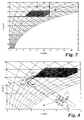
- the usual representation of the air conditions in the hx diagram is used for this (Fig. 1).
- the comfort area BG marked in FIG. 1 is important for determining the room air setpoints.
- the indoor air conditions must lie within or on the borders of this area.
- the outside air condition AU marked by t AU , x AU can be inside or outside the comfort zone.
- the following air treatment operations must be carried out: heating, cooling, humidifying, dehumidifying.
- t AB With proper operation of the control of air condition is t AB, AB x exactly on the air setpoints R should.
- AU x t At the end of the air conditioning system to supply air TO (t, x to) be brought.
- the area NE 1 is the area in which the outside air share Is 100%, which means that the outside air condition corresponds to the supply air setpoint.
- the area NE 0 is the area from which the outside air condition AU is minimal Outside air portion can be converted to the supply air state CLOSED.
- the two areas NE 1 and NE 0 limit the zero energy area in which only the mixing operation or energy recovery is necessary.
- An upstream step in the process consists in determining and deciding the boundaries of the zero energy area, whether the outside air condition AU is in this area.
- Fig. 3 describes the case of room cooling and dehumidification (a) or humidification (b) for two different exhaust air conditions AB.
- air treatment operations Mix cool and moisturize to carry.
- a conflict between the operations belonging to both exhaust air conditions AB between cooling and humidifying As if looking at the there is a conflict between the operations belonging to both exhaust air conditions AB between cooling and humidifying.
- Fig. 4 represents the case of space heating, again with dehumidification (a) and humidification (b) for each of two exhaust air conditions.
- AB must be mixed, heated and humidified here which creates a conflict between humidification and heating.
- control method is also dependent on the mixed air status (h M , x M ) and the room air status, expressed by the exhaust air status AB.
- the target value R to the exhaust state is the desired size.
- the path from the outside air state AU to the supply air state CLOSED depends on the control of the mixing chamber u MK , the cooler u K and the steam humidifier u B.
- the control signal for the mixing chamber in particular has a considerable influence since it determines the position of the mixing point M.
- the above-described definition of the start value of the control signal u MK now comes into play here.
- a start value determined by the parameters in Table 1 and converted by an algorithm is selected.
- Table 1 should be interpreted as follows: The known room loads, i.e. Heat and moisture loads are applied to the pole (coordinate origin) of the h-x diagram created. This will determine a new point. This point has opposite a change in temperature and humidity to the pole. The direction of this Change (gradient) is rated zero, positive or negative. With it and with the 7, table 1 is completely determined. The sizes given are stored as an algorithm.
- the optimized room air setpoint is determined by cyclically calculating a target function value in a tx diagram.
- a start signal is defined for the mixing point M, and then required values for the temperature and humidity treatment are formed as a vectorial difference between the mixing point M and the supply air setpoint determined by the room load and the exhaust air condition AB.
- the demand values are multiplied by the direction vectors for the air treatment operations and applied to the mixing point M in the tx diagram.
- the specific enthalpies are calculated for the end points of these demand vectors y x , y t . From the difference between these values multiplied by specific evaluation factors that implement the adaptation to the respective target function, the target function value is calculated as an intermediate value and the linear optimization is continued until the optimized room air setpoint is reached.
- the starting value for the control signal u MK results in the mixing point M, which characterizes the air state after the mixing chamber. From this point, the known supply air condition CLOSED must be reached.
- the two variables t MZU and x MZU represent the temperature and the moisture difference between these two states. Based on these two vectors, the requirement vectors for the temperature treatment y t and the moisture treatment y x are formed.
- This value must be added to the vector t MZU and thus results in the demand vector y t .
- these demand vectors are created at the mixing point M.
- the specific enthalpies for the mixing point M and the end points of the temperature requirement vector y t and for the supply air setpoint are now formed by an hx module.
- the difference between the specific enthalpy at the mixing point M and that at the end point of the temperature requirement vector is the specific enthalpy for the heat treatment h K (in FIG. 5).
- the difference between the specific temperature at the end point of the temperature requirement vector and the specific enthalpy of the supply air setpoint is equal to the specific enthalpy for humidification h B.
- a second implementation variant of the method according to the invention is described with reference to FIG. 8 for the case of a positive heat load with mixing, cooling and humidifying.
- the cyclic run of the one-dimensional optimization process of the optimal room air setpoint is carried out by calculating a target function value in a tx diagram, using, starting from a start value of the control signal for the mixing point M defined by the start condition, required values for the temperature and humidity treatment as a vectorial difference between the mixing point M and the supply air setpoint ZU determined by the room load and the exhaust air state AB, the demand values are multiplied by the direction vectors for the air treatment operations and specific evaluation factors k that implement the adaptation to the respective target function, and multiplied by the mixing point M in the tx diagram be created.
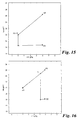
- the demand vectors y x , y t determined in this way are projected onto a projection line P, which runs orthogonally to the isenthalpy I through the mixing point M and the target function values (as intermediate values) are formed by scalar addition of the amounts of these projection values h K , h B.
- the starting point is again the demand vectors for temperature and humidity.
- the target function value can be used in both implementation variants of the method the known values for the outside air, exhaust air and supply air status AU, AB, ZU are calculated and is with constant outside air content and constant heat or Moisture load only depends on the exhaust air condition AB.
- the optimization process i.e. is the determination of the exhaust air condition AB, which is assumed to be known above thus only a one-dimensional problem that can be easily solved.
- the optimal room air setpoint R opt that minimizes the target function value should be searched for within the limits of the comfort zone . There are known and simple optimization methods for this. For example, the search procedure for the golden ratio can be used.
- intervals are formed in the search procedure for the golden section and the target function values are compared with one another at the interval limits.
- the search process continues to divide until it falls below a specified iteration accuracy.
- the number of steps required depends on the desired accuracy and can be easily estimated. For example, nine steps are necessary to achieve an accuracy of 10 -02 that is sufficient for technical purposes.
- the chosen one-dimensional search procedure needs to be modified a little.
- extensive Investigations of the target function mountains have shown that it is singular Points on the limits of the search interval can give the one required here Search procedure should also find.
- the optimization process modified so that the target function values are explicit on both limits of the interval calculated and compared with the result of the search within the interval limits become.
- the method according to the invention is general for all operating cases (heat loads, Moisture loads) and unit series (especially for steam humidifiers and Air washer) applicable. In contrast to the previously known methods in the present case the optimization with reasonable effort to an exact Result.
- the algorithm can be used on the usual with economic effort Automation devices of building automation can be realized.
- the supply air controller no longer has to be a PID controller. In fact, they are complete other controller algorithms, such as fuzzy controllers or neural networks, are conceivable.
- FIG. 9 shows a diagram for a device for implementing the method, in particular with a representation of the necessary input information. From the measured values for the outside temperature t AU and the relative humidity of the outside air ⁇ AU , the values for h AU and x AU are implemented in a common electronics module for calculating the air conditions (module 1) and implemented in the program.
- the values for the heat load h WL and the moisture load x FL are necessary for this. Either these values are known and constant or they have to be calculated from the values t WL and X FL using the hx module.
- t WL and x FL are differences between room air and supply air temperature or room air and supply air humidity. In the steady state, these values can be obtained from the setpoints of the corresponding controllers.
- the design values should be entered here. All other input information in the actual algorithm (implemented in module 2; MODULE 2) are known constant parameters.
- the output information of module 2 is the setpoints for the room air status h Rsoll and x Rsoll as well as the binary demand signals for the cooler and the humidifier, or alternatively release signals for the two slave controllers .
- the process is not limited to a constant, minimal proportion of outside air. If the minimum proportion of outside air changes, u MKmin becomes variable.
- the algorithm takes into account the respective value of u MKmin . However, this value is assumed to be constant for the duration of the solution to the optimization process.
- the second process step now solves the second sub-problem of optimal control:
- G k VE ⁇ H VE 100 ⁇ m to ⁇ u VE + k K ⁇ H K 100 ⁇ m to ⁇ u K + k B ⁇ H B 100 ⁇ m to ⁇ u B + k NE ⁇ H NE 100 ⁇ m to ⁇ u NE
- the optimal room air setpoint is now assumed or used.
- the Treatment is analogous to the first process step already described.
- the Optimization can again be represented geometrically and interpreted.
- the two implementation variants described can be used.
- the method according to the invention is intended to be implemented with the projection Demand vectors are presented. This is to be done using FIG. 8.
- the optimal control signal u ij opt for the mixing chamber or for the energy recuperator is determined in a cyclical run through the one-dimensional optimization method by calculating a target function value in a tx diagram.
- required values for the temperature and humidity treatment are formed as a vectorial difference between the mixing point M and the supply air setpoint determined by the room load and the exhaust air condition AB.
- the demand values are multiplied by the direction vectors for the air treatment operations and specific evaluation factors k, which implement the adaptation to the respective target function, and applied to the mixing point M in the tx diagram.
- the demand vectors y x , y t determined in this way are projected onto a projection line P, which runs orthogonally to the isenthalpy I through the mixing point M.
- the target function values are then formed by scalar addition of the amounts of these projection values h K , h B.
- intermediate values for the desired control signals are thus formed and the cyclical run continues until the optimal control signals u ij opt are reached .
- the exhaust air condition AB is optimized by the Room condition specified after the first process step.
- the mixing, cooling and humidifying operations shown steam humidifier
- the size of interest for optimization is Control signal for the mixing chamber, since this means both the temperature and the Moisture is affected.
- the other two operations are cooling and humidifying clearly assigned to an aggregate, so that the control of these aggregates can be done via a controller, which as setpoints the respective setpoint for gets the supply air state CLOSED.
- H VE h VE100 ⁇ U VE
- H K h K100 ⁇ U K
- H B h B100 ⁇ U B
- h NE h NE100 ⁇ U NE
- this optimization method can be solved by searching on the straight section in the tx diagram representing the mixing chamber, i.e. from AU to AB, taking into account the limitation u MKmin , ie the minimum outside air fraction .
- the optimum control signal u MK for the mixing chamber or for the energy recuperator is determined as previously described by calculating a target function value in a tx diagram.
- Treating a negative Thermal load is completely analog and should not be shown here. Likewise moisture loads can be taken into account without changing the procedure.
- the optimal exhaust air setpoints lie exactly on the corner points of the comfort area. These points may not be resolved by the serial solution of the two Partial steps found. Therefore, for the combinations mentioned above all key points of the comfort area are searched. That means that for these key points determined the control signals for the mixing chamber, the target function values must be calculated and compared with the previous result.
- An advantage of the method according to the invention is that it can be decided from the start whether the additional search including the key points is necessary. This decision is correlated with the starting conditions found and the resulting value of the start signal for u MK and can be made analogously. As already described, this is handled via table 1.
- the method according to the invention can be used for all essential rows of units and Operating cases are applied.
- an energy recuperator (ERG or WRG) can also be used (Fig. 10). If the exhaust air condition AB is evaluated with the heat recovery rate ⁇ t2 or the heat recovery rate ⁇ x2 , the maximum possible initial status of the energy recovery device TO WRG results.
- the points AU and ZU WRG now form a straight line section in the tx diagram, which describes all possible changes in state due to the energy recuperator. Analogous to the optimization of the control signals for the mixing chamber (mixing point M), the one-dimensional optimization takes place along this straight line section. The optimal state variable for the energy recuperator lies on this straight section.
- the demand vector y x now differs from that in the case of the steam humidifier. Since humidification takes place along the fog isotherms for the water temperature, this demand vector receives a clear temperature component.
- the demand vector y x is obtained by multiplying the vector x MZU by the direction vector for the humidification (increase in fog isotherms).
- the vector y x contains a temperature component, this value must be added to the vector t MZU and thus results in the demand vector y t .
- variable volume flow system (WS), which is conventionally implemented by a sequence of the master controller of the temperature cascade.
- This control variable can thus be assigned to the regulation. That before The method described is then used unchanged. This becomes a procedure here described, the universal and exact control task under optimization aspect solves.
- the device consists essentially of a controller - preferably a PLC - with the help of hardware and programming technology inventive method is realized.
- individual are preferred programmable electronic components the different process steps “determination the optimal room air setpoints "," optimal control of the air treatment units " and “determination of a start signal” implemented in terms of hardware and in terms of programming processed.
- the arrangement is shown as an example for the unit arrangement: mixing chamber / ERG, preheater, cooler, steam humidifier and post-heater.
- the module 2 supplies the optimal room air setpoints and the binary demand signals for the cooler and the humidifier.
- the optimal room air setpoints are the input information for module 3, in which the method for optimal control of the mixing chamber / ERG is implemented and processed there.
- Other input signals are the outside air status AU (h AU , x AU ) and the setpoints for the supply air status CLOSE (h Zusoll and x Zusoll ), which are available as output signals from the master controller for room temperature and humidity.
- the output signal of module 3 is the signal for direct control of the mixing chamber / ERG.
- VVS volume flow system
- Fü-R master controller
- Fo-R slave controller of Cascade
- TC temperature control
- XC humidity control
- SEQ sequence block.
- the difference to the conventional automation structures is that that the mixing chamber / ERG are controlled directly, i.e. not via sequences.
- the binary demand signals switch the cooler and humidifier on or off.
- the control strategies implemented in module 2 prevent that both the temperature and the humidity controller access the cooler. This means that the otherwise usual maximum selection is not necessary. But it can also can be provided without disadvantage - as usual.
- the preheater is over a Pre-control in the form of a temperature control with a constant setpoint (for example 18 ° C).
- the underlying unit series is: mixing chamber, preheater, cooler, steam humidifier, post-heater.
- the method according to the invention (linear optimization method) was used for this output data. with an exact mathematical optimization calculation using compared to an extensive model.
- the optimal room air condition is determined.
- the start value for the control signal is taken from Table 1.
- the optimal exhaust air condition AB is determined with this value.
- the result is shown in Fig. 13.
- FIG. 16 shows the implementation variant with the calculation of the enthalpies of the demand vectors and FIG. 17 shows the variant with the projection onto the orthogonal Isenthalpie. Finally, the course of all changes in state is based on the determined Control signals shown in Fig. 13.
- the comparison with the comparison optimization program shows determined values that are only different in the third digit after the decimal point.
Landscapes
- Engineering & Computer Science (AREA)
- Health & Medical Sciences (AREA)
- Artificial Intelligence (AREA)
- Computer Vision & Pattern Recognition (AREA)
- Evolutionary Computation (AREA)
- Medical Informatics (AREA)
- Software Systems (AREA)
- Physics & Mathematics (AREA)
- General Physics & Mathematics (AREA)
- Automation & Control Theory (AREA)
- Air Conditioning Control Device (AREA)
Applications Claiming Priority (2)
| Application Number | Priority Date | Filing Date | Title |
|---|---|---|---|
| DE10058429A DE10058429C2 (de) | 2000-11-24 | 2000-11-24 | Verfahren und Vorrichtung zur Steuerung von Lufttemperatur und Luftfeuchte in Räumen mittels einer Klimaanlage |
| DE10058429 | 2000-11-24 |
Publications (2)
| Publication Number | Publication Date |
|---|---|
| EP1209547A2 true EP1209547A2 (fr) | 2002-05-29 |
| EP1209547A3 EP1209547A3 (fr) | 2004-02-25 |
Family
ID=7664552
Family Applications (1)
| Application Number | Title | Priority Date | Filing Date |
|---|---|---|---|
| EP01127375A Withdrawn EP1209547A3 (fr) | 2000-11-24 | 2001-11-22 | Procédé et dispositif pour réguler les paramètres de l'air présent dans des locaux au moyen d'une climatisation |
Country Status (3)
| Country | Link |
|---|---|
| EP (1) | EP1209547A3 (fr) |
| DE (1) | DE10058429C2 (fr) |
| NO (1) | NO20015724L (fr) |
Cited By (3)
| Publication number | Priority date | Publication date | Assignee | Title |
|---|---|---|---|---|
| CN103235618A (zh) * | 2012-10-08 | 2013-08-07 | 工布设计有限公司 | 一种温湿度先决控制方法以及应用该方法的加湿装置 |
| CN103293960A (zh) * | 2013-06-05 | 2013-09-11 | 重庆科技学院 | 基于模糊推理技术与存储器地址映射的舒适度传感器 |
| EP2667278A1 (fr) | 2012-05-25 | 2013-11-27 | GfR - Gesellschaft für Regelungstechnik und Energieneinsparung mbH | Procédé et dispositif de commande des paramètres d'air dans des pièces |
Families Citing this family (5)
| Publication number | Priority date | Publication date | Assignee | Title |
|---|---|---|---|---|
| DE10254498C2 (de) * | 2001-11-30 | 2003-12-11 | Tocama De Candias Sl Puerto De | Verfahren und Temperaturregelvorrichtung zum Feuchtigkeits-abhängigen Regeln der Innentemperatur eines Raumes |
| DE102004001193A1 (de) * | 2004-01-05 | 2005-07-28 | Behr Gmbh & Co. Kg | Verfahren und Anordnung sowie Computerprogramm mit Programmcode-Mitteln und Computerprogramm-Produkt zur Ermittlung einer Steuergröße für eine Temperaturregelung für ein System |
| DE102017106856A1 (de) * | 2017-03-30 | 2018-10-04 | Techem Energy Services Gmbh | Verfahren und Vorrichtung zur Ermittlung der Wahrscheinlichkeit für einen Schimmelpilz- und/oder Feuchteschaden in einem Gebäude |
| DE102019119032A1 (de) * | 2019-07-12 | 2021-01-14 | Fraunhofer-Gesellschaft zur Förderung der angewandten Forschung e.V. | Kammer mit diffusionsoffener Wärmedämmung zur Trocknung oder Klimatisierung von Gütern |
| CN115220500B (zh) * | 2021-06-04 | 2024-04-19 | 广州汽车集团股份有限公司 | 环境参数控制方法、控制终端和环境模拟系统 |
Family Cites Families (5)
| Publication number | Priority date | Publication date | Assignee | Title |
|---|---|---|---|---|
| CH685259A5 (de) * | 1992-09-16 | 1995-05-15 | Landis & Gyr Betriebs Ag | Verfahren zur Steuerung einer Klimaanlage. |
| DE4330646C2 (de) * | 1993-09-10 | 1995-08-03 | Meyer Fa Rud Otto | Verfahren zum Regeln von Temperatur und Feuchte von Luft in Räumen mittels einer raumlufttechnischen Anlage |
| EP0786712B1 (fr) * | 1996-01-29 | 2001-04-04 | Siemens Building Technologies AG | Méthode et dispositif de régulation de la température et de l'humidité dans une installation de climatisation |
| US5675979A (en) * | 1996-03-01 | 1997-10-14 | Honeywell Inc. | Enthalpy based thermal comfort controller |
| DE19834275A1 (de) * | 1998-07-30 | 2000-02-24 | Rud Otto Meyer Gmbh & Co Kg | Verfahren zum optimierten Steuern und Regeln von Klimaanlagen |
-
2000
- 2000-11-24 DE DE10058429A patent/DE10058429C2/de not_active Expired - Fee Related
-
2001
- 2001-11-22 EP EP01127375A patent/EP1209547A3/fr not_active Withdrawn
- 2001-11-23 NO NO20015724A patent/NO20015724L/no not_active Application Discontinuation
Cited By (4)
| Publication number | Priority date | Publication date | Assignee | Title |
|---|---|---|---|---|
| EP2667278A1 (fr) | 2012-05-25 | 2013-11-27 | GfR - Gesellschaft für Regelungstechnik und Energieneinsparung mbH | Procédé et dispositif de commande des paramètres d'air dans des pièces |
| CN103235618A (zh) * | 2012-10-08 | 2013-08-07 | 工布设计有限公司 | 一种温湿度先决控制方法以及应用该方法的加湿装置 |
| CN103293960A (zh) * | 2013-06-05 | 2013-09-11 | 重庆科技学院 | 基于模糊推理技术与存储器地址映射的舒适度传感器 |
| CN103293960B (zh) * | 2013-06-05 | 2015-10-28 | 重庆科技学院 | 基于模糊推理技术与存储器地址映射的舒适度传感器 |
Also Published As
| Publication number | Publication date |
|---|---|
| DE10058429A1 (de) | 2002-07-04 |
| NO20015724D0 (no) | 2001-11-23 |
| NO20015724L (no) | 2002-05-27 |
| EP1209547A3 (fr) | 2004-02-25 |
| DE10058429C2 (de) | 2002-10-31 |
Similar Documents
| Publication | Publication Date | Title |
|---|---|---|
| EP2667278B1 (fr) | Procédé et dispositif de commande des paramètres d'air dans des pièces | |
| EP1934665B1 (fr) | Dispositif pour assurer la commande d'une temperature ambiante dans un batiment, au moyen d'un dispositif de commande a prediction | |
| DE112008001872B4 (de) | Extremwertregelung mit Rücksetzsteuerung | |
| DE69518499T2 (de) | Regelung der Antriebsmaschine einer verteilten Klimaanlage | |
| WO2009156146A1 (fr) | Appareil aéraulique et procédé d'utilisation d'un tel appareil aéraulique | |
| EP3438567A1 (fr) | Capteur logiciel destiné à l'identification et au réglage ou à la commande d'un système de pompe à chaleur | |
| DE2606072A1 (de) | Verfahren und anlage zur steuerung der temperatur in mehreren raeumen, die wechselseitig unterschiedlichen und sich veraendernden waermebedarf haben, wobei einige der raeume normalerweise einen kuehlbedarf haben | |
| EP2136147A2 (fr) | Procédé et dispositif de réglage de la température, de l'humidité et de la teneur en dioxyde de carbone de l'air dans des pièces | |
| WO2010088893A1 (fr) | Procédé et dispositif de refroidissement d'air et de déshumidification d'air | |
| DE10058429C2 (de) | Verfahren und Vorrichtung zur Steuerung von Lufttemperatur und Luftfeuchte in Räumen mittels einer Klimaanlage | |
| EP2818803A1 (fr) | Procédé de régulation d'un système de climatisation dans un bâtiment au moyen d'au moins une installation technologique ou domestique | |
| WO2008025453A1 (fr) | Procédé pour faire fonctionner un réseau de tuyauterie | |
| Shao et al. | Investigation on weights setting rule for weights-based fuzzy logic control algorithm utilized in direct expansion air-conditioning systems | |
| Kasahara et al. | Physical model of an air-conditioned space for control analysis | |
| EP0643271B1 (fr) | Procédé pour la régulation de la température et de l'humidité dans les enceintes utilisant une installation de climatisation d'air | |
| EP3640565A1 (fr) | Régulation de la puissance optimale cop | |
| EP3168540A1 (fr) | Procédé d'exécution d'un équilibrage hydraulique automatisé, soupape et installation de chauffage associées | |
| EP0588052B1 (fr) | Méthode et système pour le contrÔle et la régulation d'une installation de climatisation | |
| DE102016201745A1 (de) | Softsensor zur Identifikation und Regelung oder Steuerung eines Lüftungssystems | |
| JP3233567B2 (ja) | 制御アルゴリズム自動獲得装置 | |
| DE102022118111A1 (de) | Verfahren zur Regelung von thermischen Raumpunkten | |
| DE19942491A1 (de) | Verfahren zum Regeln einer Zuluft-Konditionieranlage und Regelvorrichtung für eine Zuluft-Konditionieranlage | |
| DE112023005905T5 (de) | Kältekreislauf-Vorrichtung vom Mehrfachtyp | |
| EP2369252A2 (fr) | Procédé de refroidissement d'une pièce | |
| DE4319659A1 (de) | Verfahren zum Regeln von Temperatur und Feuchte von Luft in Räumen |
Legal Events
| Date | Code | Title | Description |
|---|---|---|---|
| PUAI | Public reference made under article 153(3) epc to a published international application that has entered the european phase |
Free format text: ORIGINAL CODE: 0009012 |
|
| AK | Designated contracting states |
Kind code of ref document: A2 Designated state(s): AT BE CH CY DE DK ES FI FR GB GR IE IT LI LU MC NL PT SE TR |
|
| AX | Request for extension of the european patent |
Free format text: AL;LT;LV;MK;RO;SI |
|
| PUAL | Search report despatched |
Free format text: ORIGINAL CODE: 0009013 |
|
| AK | Designated contracting states |
Kind code of ref document: A3 Designated state(s): AT BE CH CY DE DK ES FI FR GB GR IE IT LI LU MC NL PT SE TR |
|
| AX | Request for extension of the european patent |
Extension state: AL LT LV MK RO SI |
|
| RIC1 | Information provided on ipc code assigned before grant |
Ipc: 7F 24F 11/00 B Ipc: 7G 05B 13/02 B Ipc: 7G 05D 23/19 A |
|
| AKX | Designation fees paid |
Designated state(s): AT BE CH CY DE DK ES FI FR GB GR IE IT LI LU MC NL PT SE TR |
|
| STAA | Information on the status of an ep patent application or granted ep patent |
Free format text: STATUS: THE APPLICATION IS DEEMED TO BE WITHDRAWN |
|
| 18D | Application deemed to be withdrawn |
Effective date: 20040826 |