EP1209625A2 - Appareil et procédé pour le codage d'images - Google Patents
Appareil et procédé pour le codage d'images Download PDFInfo
- Publication number
- EP1209625A2 EP1209625A2 EP01127595A EP01127595A EP1209625A2 EP 1209625 A2 EP1209625 A2 EP 1209625A2 EP 01127595 A EP01127595 A EP 01127595A EP 01127595 A EP01127595 A EP 01127595A EP 1209625 A2 EP1209625 A2 EP 1209625A2
- Authority
- EP
- European Patent Office
- Prior art keywords
- picture
- frame rate
- code amount
- coding
- value
- Prior art date
- Legal status (The legal status is an assumption and is not a legal conclusion. Google has not performed a legal analysis and makes no representation as to the accuracy of the status listed.)
- Withdrawn
Links
Images


Classifications
-
- G—PHYSICS
- G06—COMPUTING OR CALCULATING; COUNTING
- G06T—IMAGE DATA PROCESSING OR GENERATION, IN GENERAL
- G06T9/00—Image coding
- G06T9/005—Statistical coding, e.g. Huffman, run length coding
Definitions
- the present invention is related to a picture coding apparatus and a picture coding method, for re-coding a digital compressed picture signal to obtain such a digital picture signal having either the same compression format or the different compression format from that of the digital compressed picture signal. More specifically, the present invention is directed to a picture coding apparatus and a picture coding method, capable of increasing a bit using efficiency when a digital compressed picture signal as an input picture signal is re-coded so as to reducing a number of frame skipping operations in the case that a total frame number of the digital compressed picture signal per unit time is varied.
- Such a television conference system may be realized by a picture compression technique capable of compressing digitalized conference pictures so as to obtain a predetermined amount of conference data which can be transferred in real time within the frequency band of the narrowband ISDN.
- Fig. 8 represents an example of a picture transmission in a television conference system.
- narrow bands low bit rate
- 64 Kbps 64 kilobits per second
- 128 Kbps 128 Kbps
- the quantizing control corresponds to such a control in which code amounts allocated to each picture and each macroblock contained in a picture are determined, and quantizing steps are determined based upon these determined code amounts.
- the frame skipping control corresponds to such a control in which when an amount of data which have already been coded but have not yet been transferred (namely, output buffer remaining amount) exceeds a constant amount, the next picture is not coded, but skipped.
- VM16 As a concrete example of such a rate control, there is the method described in "MPEG-4 Video Verification Model version 16.0" of ISO/IEC JTC1/SC29/WG11 N3312 (will be abbreviated as a "VM16" hereinafter).
- This VM16 indicates an example of realizing the concrete compressing/decoding system of MPEG-4 Video (ISO/IEC 14496-2), and implies the general-purpose system having high practical possibilities.
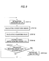
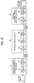
- Fig. 9 shows a flow chart for describing the rate control executed based upon VM16.
- a parameter required for executing the rate control is set as an initializing process.
- a target code amount allocated to a picture which is presently encoded is calculated in accordance with the below-mentioned sequence (expressions are described by C language program. Various sorts of below-mentioned process operations are similarly described by C Language program).
- T Max(Rs/30, Rr/Nr*0.95+S*0.05);
- T T*(B+2*(Bs-B)/(2*B+(Bs-B));
- a quantizing value is determined in response to the target code amount acquired at the step 20.
- an output buffer remaining amount, a remaining picture number, and the like are updated.
- steps 50-1 and 50-2 when the output buffer remaining amount exceeds 80% of the output buffer capacity, the next frame is skipped by the frame skipping control.
- an image segment indicates a group (cluster) of pictures which are theoretically segmented by certain constant time. For instance, assuming now that a segment is separated at every 1 second, a total number of pictures contained in this segment is equal to a frame rate. For example, in the case that pictures are coded at a frame rate of 10 pictures per 1 second, 10 screens of pictures are contained by 1 segment.
- a coding frame rate is determined, and a coding operation should be carried out based upon the coding frame rate.
- Other general-purpose methods which are not described in this specification are also performed in a similar manner. That is, while coding frame rate is determined, a code amount to be allocated is calculated by using the determined coding frame rate.
- a coding frame rate owns such an implication of a parameter which indicates a time duration defined from a time instant when a coding operation is presently carried out up to a coding operation of a next frame. For instance, when a coding frame rate is equal to 10 pictures/second, it can be seen that a time duration after one picture has been coded until a next picture is coded is equal to 0.1 second.
- a coding frame rate may be freely set on the side of the transmission terminal in such a manner that this coding frame rate becomes equal to an integer-th of the output frame rate of the television camera, whereas images may be acquired under stable condition by the television camera in the compression unit provided on the side of the transmission terminal.
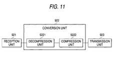
- a picture compressing unit 911 of a television conference terminal 91 provided on the transmission side, a rate control is carried out with respect to a picture signal which owns the known constant frame rate and is derived from a television camera.
- the rate-controlled picture signal is transmitted via a transmission unit 912 to a transmission path, and is inputted into a system converting apparatus 92.
- a conversion unit 922 of the system converting apparatus 92 is arranged by an decompression unit 9221 and a compression unit 9222.
- the decompression unit 9221 decompresses a picture, compressed by a compression system of an input side and derived from a reception unit 921, so as to produce a decompressed picture .
- the compression unit 9222 recompresses this decompressed picture by way of a compression system of an output side.
- the recompressed picture signal is sent via a transmission path to a television conference terminal 93 provided on the reception side.
- the recompressed picture signal received by a reception unit 931 is converted by an decompression unit 932 into a decompressed picture which will be displayed on a television monitor.
- the input picture of the picture compression unit 911 of the television conference terminal 91 provided on the transmission side corresponds to the picture having the known constant frame rate
- the input picture of the compression unit 9222 employed in the system converting apparatus 91 corresponds to such a picture which has been once coded by the low bit rate and thereafter is decompressed.
- the picture compression system of the low bit rate such as MPEG-4 video and the ITU-T recommendation H.261
- the frame rate of the input picture of the picture compression unit 9222 employed in the system converting apparatus 92 is unknown.
- there are many cases that frames are skipped in the frame skipping control during the coding operation in the terminal of the transmission side.
- the frame rate is not constant. In other words, after one picture is inputted, it is not clear when the next picture is inputted. As a result, in such a case that the above-explained general-purpose rate control is employed when the picture coding operation is carried out within the system converting apparatus 92, the below-mentioned problem will occur.
- the coding frame rate is set to, for example, 15 pictures/second
- the frame rate employed in the calculation of the target coding amount in the rate control is equal to 15 pictures/second
- the allocated code amount is small for the picture to be compressed at 7.5 pictures/second.
- the produced amount is decreased as compared with the allowed range (frame skipping threshold value).
- the output buffer cannot afford to produce the codes. As a result, there is no data in the output buffer to be transmitted, the time duration during which the transmission path is used in a useless manner is prolonged.
- Fig. 12 shows this example.
- Fig. 12 represents such an example of a transition of an output buffer remaining amount when the above-explained code amount allocating method by VM16 is employed.
- abscissas thereof denote a time instant.
- ordinates of these drawings show bit amounts left in the output buffer with respect to an output buffer remaining amount (line "B" shown in drawings) by values along a right axis.
- the ordinate of this histogram represents any values other than the zero in the case that the relevant picture is present at the relevant time instant, and also shows the zero in the case that the relevant picture is not present at this relevant time instant, namely, shows as to whether or not the picture is present.
- a difference between a total number of non-zero values of an input picture and a total number of non-zero values of an output picture indicates a total number of pictures which are frame-skipped by the frame skipping control.
- this graphic representation of Fig. 12 simulates operations of an encoder (coding device) accomplished by VM16 by setting the following assumption:
- a length of 1 image segment 1 second
- the coding frame rate is set to 30 pictures/second.
- the code amount is allocated, such a code amount by which a picture transmission is completed by 1/30 seconds may constitute a reference of the code amount allocated to each of the pictures.
- the coding frame rate is equal to 10 pictures/second even at such a place that no frame is skipped in the actual input picture, the interval between the pictures is equal to 1/10 seconds.
- the target code amount is corrected in such a manner that the allocation code amount is made larger than the reference code amount.
- the correction corresponds to a coefficient with respect to the reference code amount, and becomes approximately 2 in maximum in VM16.
- This correction may have an effect in view of the following implication. That is, in the case that pictures can be entered under stable condition which is set by the coding unit, the code amount may be stably allocated.
- the target code amount which is corrected based upon the coefficient becomes approximately 4300 bits, so that such a condition is continued under which the output buffer remaining amount becomes low.
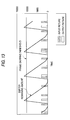
- Fig. 13 shows an output buffer remaining amount in the case that while a coding frame rate is set to 7.5 pictures/second, a coding operation is carried out with respect to an input picture whose coding frame rate is 10 pictures/second.
- a coding operation is carried out with respect to an input picture whose coding frame rate is 10 pictures/second.
- 11 pictures are entered, only 5 pictures are outputted, and thus, the remaining 6 pictures are frame-skipped.
- skipping of the two pictures is caused by the mismatching of the set coding frame rate with respect to the input frame rate, which cannot be solved by the rate control system.
- skipping of the remaining four pictures is caused by the frame skipping control.
- the (motion) picture to be outputted may become (motion) pictures lacking smoothness, as compared with the input (motion) pictures.
- the code amount with respect to such a picture which is originally to be coded becomes useless, and the image quality would be deteriorated.
- an object of the present invention has an object to solve the above-explainedproblems.
- an object of the present invention may be achieved by that in a picture coding operation used in a system converting apparatus, a usable code amount can be effectively used with respect to an input picture whose frame rate is unknown and also is variable. Furthermore, an occurrence of a new skipping operation is reduced with respect to such an input picture that frames of this input picture are skipped, and an interval between frames is varied.
- a picture coding method is featured by such a picture coding method for executing a coding control in such a manner that a target code amount is calculated every picture to be coded and a generated code amount of the picture to be coded is approximated to the target code amount, in which: the target code amount of the picture to be coded is calculated by adding a correction amount to a reference target code amount which is approximately constant; the reference target code amount is calculated from a reference coding frame rate; and the correction value is calculated based upon a difference between a predetermined target value and an actual value of a remaining coded picture amount of such a picture which has already been coded and has not yet been outputted from an apparatus.
- the usable code amount can be continuously and effectively utilized by the correction value.
- the target value of the remaining coded picture amount is determined based upon a frame-skipping threshold value corresponding to a threshold value used to judge as to whether or not a next picture is coded. As a result, such a code amount allocation in which a frame skipping operation can hardly occur can be carried out.
- the predetermined target value of the remaining coded picture amount is determined based upon the reference target code amount. As a consequence, the code amount which is further approximated to the reference target code amount can be produced.
- a frame rate of an inputted picture is measured; and the reference coding frame rate is determined based on the measured frame rate.
- the code amount which is suitable for the actual coding operation can be produced.
- the reference coding frame rate is determined based upon a maximum value of the measured frame rate. As a result, it is possible to reduce an occurrence of such a frame-skipping operation which is caused by a rapid variation in the frame rates.
- the reference coding frame rate is determined based upon an average value of the measured frame rates within constant time. As a result, such a code amount allocation which is fitted to a variation in input frame rates can be carried out.
- the reference coding frame rate is updated based upon the average value of the measured frame rates within the constant time
- a reference coding frame rate before being updated is larger than a reference coding frame rate after being updated
- a value between the reference coding frame rate before being updated and the reference coding frame rate after being updated is used as the reference coding frame rate after being updated.
- Another aspect of the present invention is a picture coding apparatus for coding an inputted image to output a compression picture signal, comprising a rate control unit having a function capable of adjusting a code amount generated every picture of the inputted image, which is to be coded; and an output buffer having a function capable of storing thereinto a generated code until the stored code is outputted from the picture coding apparatus; wherein the rate control unit controls the rate in such a manner that a target code amount of the picture to be coded is calculated by adding a correction value to a reference target code amount which is approximately constant and a generated code amount of the picture to be coded is approximated to the target code amount; the reference target code amount is calculated based upon a reference coding frame rate; and the correction value is calculated based upon a difference between a predetermined target value and an actual value of a buffer remaining amount corresponding to a code amount left in the output buffer.
- a picture coding in which the usable code amount can be continuously and effectively utilized by the correction value is realized
- Yet another aspect of this invention is an image relaying apparatus, comprising an image receiving unit to receive an image from an external image transmission unit, an image transmission unit to transmit an image to an external image receiving unit, and a picture coding unit, for converting an image in a first image format received from the external transmission unit to a second image format suitable for the external receiving unit and transmitting the image in the second image format to the external receiving unit, wherein the picture coding unit comprising: a rate control unit having a function capable of adjusting a code amount generated every picture of an inputted image, which is to be coded; and an output buffer having a function capable of storing thereinto a generated code until the stored code is outputted from the picture coding apparatus; wherein the rate control unit controls the rate in such a manner that a target code amount of said picture to be coded is calculated by adding a correction value to a reference target code amount which is approximately constant and a generated code amount of the picture to be coded is approximated to the target code amount; the reference target code amount is calculated based upon a
- Fig. 1 is a functional block for showing an arrangement of a picture coding apparatus according to a first embodiment of the present invention.
- This picture coding apparatus is to realize coding operations based upon such a general-purpose compression system as the recommendation H.261 of ITU-T and MPEG-4.
- a non-compression picture is entered into this picture coding apparatus, and a coded signal is outputted therefrom.
- the entered non-compression picture such a picture may be employed, the frame rate of which is unknown, and is dynamically changed due to frame skipping operation and the like.
- This picture coding apparatus contains a rate control unit 100, an image buffer 200, a orthogonal transformation unit 300, a quantizing unit 400, a variable length coding unit 500, a motion predicting unit 600, a decoding unit 700, and an output buffer 800.
- the rate control unit 100 allocates a code amount to each of pictures based upon a data amount of a compression picture signal stored in the output buffer 800 (will be simply referred to as a "buffer remaining amount” hereinafter), determines a quantizing amount based upon the allocated code amount, and then, transfers the determined quantizing value 100a to the quantizing unit 400. Also, while the rate control unit 100 acquires the generated code amount 500b from the variable length coding unit 500, the rate control unit 100 may properly correct the quantizing value in the unit of either one macroblock or a plurality of macroblocks, and then may transfer the corrected quantizing value 100a to the quantizing unit 400. Furthermore, the rate control unit 100 may discard an image inputted into the image buffer 200 in response to the buffer remaining amount 800a, and may output a frame skipping instruction 100b. It should be noted that only typical data flows among the respective blocks are indicated in Fig. 1.
- the image buffer 200 once stores thereinto a non-compression picture which is inputted in the unit of a picture, and supplies the entered picture 200a to either the orthogonal transformation unit 300 or the motion predicting unit 600.
- the orthogonal transformation unit 300 orthogonally transforms a prediction residual 600b which is outputted from either the inputted picture 200a or the motion predicting unit 600, and supplies the orthogonally transformed prediction residual to the quantizing unit 400.
- the quantizing unit 400 quantizes a transformation coefficient 300a which is acquired from the orthogonal transformation unit 300 based upon the quantizing value 100a designated by the rate control unit 100, and then supplies a quantized transformation coefficient 400a corresponding to this quantized result to the variable length coding unit 500.
- variable length coding unit 500 carries out variable-length coding on the quantized transformation coefficients 400a which is received from quantizing unit 400, the quantizing value, and motion vector received from motion predicting unit 600, and output the result as a compressed picture signal 500a to he output buffer 800. Also, the generated code amount 500b is transferred to the rate control unit 100.
- the motion predicting unit 600 predicts the input image 200a acquired from the image buffer based upon a reference image 700a acquired from the decoding unit 700, and supplies a motion vector 600a corresponding to the predicted result to the variable length coding unit 500, and also supplies the prediction residual 600b to the orthogonal transformation unit 300.
- the decoding unit 700 acquires such information as the quantized transformation coefficients 400a and the motion vector from the quantizing unit 400 and the variable length coding unit 500, and then decodes this acquired information in a similar manner to the decoding operation of the compression picture signal so as to form a de-compressed picture 700a which constitutes a reference image. Then, the decoding unit 700 supplies the formed de-compressed picture 700 to the motion predicting unit 600.
- the output buffer 800 temporarily stores thereinto the compression picture signal 500a produced by the variable length coding unit 500, and then outputs the stored compression picture signal outside this picture coding apparatus.
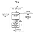
- Fig. 2 is a functional block diagram for indicating an arrangement of the rate control unit 100.
- the rate control unit 100 contains a code amount allocating means 110 and a quantizing value determining means 120.
- the code amount allocation means 110 inputs thereinto both the buffer remaining amount 800a acquired from the output buffer 800 and the generated code amount 500b which is acquired from the variable length coding unit 500, and determines an allocated code amount 110a to output this allocated code amount 110a.
- the quantizing value determining means 120 inputs the allocated code amount 110a outputted from the code amount allocating means 110, and determines the quantizing amount 100a to output this quantizing amount 100a.
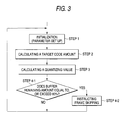
- Fig. 3 is a flow chart for describing a process flow operation of the rate control unit 100.
- the code amount allocating means 110 sets/updates an internally used parameter as an initializing process operation. It should be noted that externally acquired values such as the buffer remaining amount are newly acquired outside the picture coding apparatus.
- the code amount allocating means 110 calculates a target code amount, and transfers the calculation result as the allocation code amount 110a to the quantizing amount determining means 120.
- the quantizing value determining means 120 determines the quantizing value 100a based upon the allocated code amount 110a. Then, at a step 4-1 and another step 4-2, after the coding operation of the relevant picture has been accomplished, the code amount allocating means 110 newly acquires the buffer remaining amount 800a, and when the buffer remaining amount 800a exceeds 80% of the output buffer size, the code amount allocating means 110 outputs the frame skipping instruction 100b with respect to the image buffer 200.
- both an upper limit value and a lower limit value are provided in the allocated code amount, and then, are clipped.
- This clipping method is carried out by the following process operation as one example:
- the reference target code amount is calculated based upon the reference coding frame rate, and the correction value is calculated based upon both the buffer remaining amount and the target buffer remaining amount.
- the reference coding frame rate is set in a fixed manner based upon a predictable input frame rate of an actually entered non-compression picture to such a frame rate value which exceeds this predictable input frame rate, for example, 30 pictures/second.
- the target buffer remaining amount is determined based upon either the frame skipping threshold value of the input picture or the reference target code amount.
- the correction value " ⁇ " is not the coefficient of the reference target code amount Tt
- the resultant may be corrected independently from the reference target code amount Tt.
- the value (of " ⁇ ") may be corrected based upon the actual buffer remaining amount irrespective of this value, and the available bits may be effectively utilized.
- the reference target code amount "Tt" corresponding to the stable value namely, constant in this embodiment
- the quantizing value determining value detecting means 120 determines a quantizing value based upon an allocated code amount thereof in accordance with a general-purpose method such as, for example, the quantizing value determining method of VM16. In this case, the quantizing value determining method by VM16 is represented.
- a modeling parameter implies such a parameter used to adjust a quantizing value determining characteristic, and this modeling parameter is properly set based upon a compression system and a characteristic of an apparatus.
- the target buffer remaining amount "Bt” is determined based upon a frame skipping threshold value "Dth.”
- This frame skipping threshold value "Dth” is a set value regarding the buffer remaining amount 800a. This set value is used in order that an image entered into the image buffer 200 is discarded, and the frame skipping instruction 100b is outputted. For instance, this frame skipping threshold value "Dth” is set to 80% of the buffer size of the output buffer 800.
- Fig. 4 is a graphic representation for simulating a transition of a buffer remaining amount by the picture coding apparatus by way of a calculation with employment of this determining method. Except for the method of determining the target code amount, other conditions are identical to the simulation conditions of Fig. 12 and Fig. 13.
- the reference coding frame rate is equal to 30 pictures/second.
- the result of the prior art apparatus inwhich a similar coding frame rate is set corresponds to the simulation result of Fig. 12. Since the coding frame rate is set identical to each other, the reference target code amount before the correction in each of the pictures shown in Fig. 4 is identical to the target code amount before the correction in Fig. 12, namely is equal to approximately 2133 bits.
- the target code amount is not adversely influenced by this value, but may be corrected in response to the target buffer remaining amount.
- the buffer remaining amount becomes larger than that of the prior art.
- the time duration during which the buffer remaining amount becomes zero can be shortened, as compared with that of the prior art. Therefore, even in such a case that the input frame is dropped and thus, the interval of the frames which can be coded is prolonged, the code amount can be more effectively used, and also the deterioration in the image quality can be suppressed.
- the target code amount capable of lowering the frame skipping threshold value can be set, so that the frame skipping operations can be reduced.
- the target buffer remaining amount "Bt” is determined based upon a reference target code amount "Tt.”
- the buffer remaining amount "Bt” is a value indicative of a delay.
- a delay produced by the output buffer corresponds to a reference coding frame period.
- the lower a delay amount can be hardly recognized by a human. For instance, although a delay of 0.5 seconds contained in 10 pictures per second may become apparent, a delay of 0.5 seconds contained in 1 picture per second can be hardly recognized. Also, by allowing a large amount of delays, allowable amount of code amount for each picture may be increased. While code amounts are effectively allocated, qualities of an entire picture can be more uniformly improved.
- the delay amount can be set to the target delay amount in correspondence with the desirable frame rate during the coding operation, and the more effective code amount can be realized. Also, in the case that the reference target code amount is calculated based upon the below-mentioned method, since the reference coding rate may become such a frame rate fitted to the input picture, the correction value with small wasteful amount and adapted to the condition of the input picture can be determined in accordance with this determining method.
- the reference coding frame rate which is employed by the rate control unit 100 is fixed.
- a reference coding frame rate is determined based upon an input frame rate.
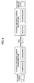
- FIG. 1 An entire arrangement of a picture coding apparatus of the second embodiment is similar to that of the first embodiment, and a functional flock of this picture coding apparatus is indicated in Fig. 1. Also, an internal arrangement of a rate control unit 100 is represented in the functional block of Fig. 5.
- the rate control unit 100 is constituted by both a code amount allocating means 110 and a quantizing value determining means 120, which is similar to those of the first embodiment. It should be understood that the code amount allocating means 110 inputs thereinto information 200b of an input frame interval which is obtained from the image buffer 200 in addition to the buffer remaining amount 800a and the generated code amount 500b.
- This input frame interval 200b corresponds to a time duration defined by that after a picture stored in the image buffer 200 is inputted into the code mount allocating means 110, a next new picture is inputted thereinto.
- an input frame interval L(n) of an n-th picture represents a time duration defined by that after (n-1)-th picture is inputted into the code amount allocating means 110, the n-th picture is inputted.
- an instantaneous input frame rate at this time instant is obtained.
- an average value thereof is calculated, so that an averaged input frame rate within the constant time may also be calculated.
- an averaged input frame rate "Favg(a, b)" defined from an a-th picture up to a b-th picture may be calculated based upon the following formula:
- a first determining method corresponds to such a method for calculating a reference coding frame rate based upon a maximum input frame rate which is measured while a coding process operation is carried out.
- a target code amount may be preferably set in such a manner that codes which are generated by coding a picture at a certain time instant may be consumed when the next picture is coded.
- an input frame interval F(n+1) is required to be calculated.
- the input frame interval F(n+1) is actually acquired in order to code an n-th picture, a delay of the length corresponding to 1 picture will occur, which is not suitable for a real-time communication.
- substitution means there is an effect that as the input frame interval F(n+1), the actual value is not used, but such a value which is calculated from the past input frame intervals is used as a predicted value.
- Fig. 6 is a graphic representation for graphically showing that a transition of a buffer remaining amount of the picture coding apparatus with employment of this determining method is simulated by way of a calculation. As indicated in this drawing, the effective allocation of the code amounts is realized under stable condition even in the case that the input picture is frame-skipped.
- the code amount allocation suitable for the input picture can be carried out, and the frame skipping can be reduced.
- a second determining method corresponds to such a method for calculating a reference coding frame rate based upon an average frame rate of input frame rates which have been acquired within a past constant time period after the coding operation was commenced.
- the reference coding frame is determined based upon the below-mentioned method. This process operation is carried out on every picture.
- a larger reference target code amount than that of the first determining method may be set.
- useless codes can be reduced, as compared with that of the first determining method.
- a third determining method is similar to the second determining method, and corresponds to the following determining method. That is, while a calculation is made of an average "Favg" of input frame rates within constant time, when the average "Favg" is larger than a reference coding frame rate "Ft" at this time, this average “Favg” is directly assigned to the reference coding frame rate "Ft", whereas when the average “Favg” is smaller than this frame rate "Ft", any value between "Favg” and “Ft", an average value for example, is assigned to "Ft.”
- the reference coding frame rate is determined based upon the below-mentioned manner. This process operation is carried out every picture.
- Fig. 7 is a graphic representation for graphically showing that a transition of a buffer remaining amount of a picture coding apparatus with employment of this determining method is simulated based upon a calculation.
- the code amount allocation can be realized in correspondence with the input frame rate, while the useless code amount canbe hardly produced similar to the second determining method.
- the larger reference target code amount can be hardly set, so that the frame skipping operation can be reduced.
Landscapes
- Engineering & Computer Science (AREA)
- Multimedia (AREA)
- Physics & Mathematics (AREA)
- General Physics & Mathematics (AREA)
- Theoretical Computer Science (AREA)
- Compression Or Coding Systems Of Tv Signals (AREA)
Applications Claiming Priority (2)
| Application Number | Priority Date | Filing Date | Title |
|---|---|---|---|
| JP2000352949 | 2000-11-20 | ||
| JP2000352949 | 2000-11-20 |
Publications (1)
| Publication Number | Publication Date |
|---|---|
| EP1209625A2 true EP1209625A2 (fr) | 2002-05-29 |
Family
ID=18825779
Family Applications (1)
| Application Number | Title | Priority Date | Filing Date |
|---|---|---|---|
| EP01127595A Withdrawn EP1209625A2 (fr) | 2000-11-20 | 2001-11-19 | Appareil et procédé pour le codage d'images |
Country Status (3)
| Country | Link |
|---|---|
| US (1) | US7082163B2 (fr) |
| EP (1) | EP1209625A2 (fr) |
| CN (1) | CN1203678C (fr) |
Families Citing this family (24)
| Publication number | Priority date | Publication date | Assignee | Title |
|---|---|---|---|---|
| JP4765194B2 (ja) * | 2001-05-10 | 2011-09-07 | ソニー株式会社 | 動画像符号化装置、動画像符号化方法、動画像符号化プログラム格納媒体及び動画像符号化プログラム |
| US7418037B1 (en) * | 2002-07-15 | 2008-08-26 | Apple Inc. | Method of performing rate control for a compression system |
| US7769084B1 (en) | 2002-07-15 | 2010-08-03 | Apple Inc. | Method for implementing a quantizer in a multimedia compression and encoding system |
| KR100484148B1 (ko) * | 2002-07-27 | 2005-04-18 | 삼성전자주식회사 | 개선된 비트율 제어 방법과 그 장치 |
| US7804897B1 (en) * | 2002-12-16 | 2010-09-28 | Apple Inc. | Method for implementing an improved quantizer in a multimedia compression and encoding system |
| US7940843B1 (en) | 2002-12-16 | 2011-05-10 | Apple Inc. | Method of implementing improved rate control for a multimedia compression and encoding system |
| CN101695132B (zh) * | 2004-01-20 | 2012-06-27 | 松下电器产业株式会社 | 图像编码方法和设备、图像解码方法和设备 |
| US20060048038A1 (en) * | 2004-08-27 | 2006-03-02 | Yedidia Jonathan S | Compressing signals using serially-concatenated accumulate codes |
| JP4543971B2 (ja) * | 2005-03-07 | 2010-09-15 | ソニー株式会社 | 符号化方法、符号化装置、符号化処理のプログラム及び符号化処理のプログラムを記録した記録媒体 |
| KR100718351B1 (ko) * | 2005-09-28 | 2007-05-14 | 주식회사 팬택 | 동영상 파일의 요약 재생 시스템 및 이를 탑재한 이동통신단말기 |
| US20070132789A1 (en) * | 2005-12-08 | 2007-06-14 | Bas Ording | List scrolling in response to moving contact over list of index symbols |
| US7958456B2 (en) * | 2005-12-23 | 2011-06-07 | Apple Inc. | Scrolling list with floating adjacent index symbols |
| US7786975B2 (en) * | 2005-12-23 | 2010-08-31 | Apple Inc. | Continuous scrolling list with acceleration |
| JP2008022405A (ja) * | 2006-07-14 | 2008-01-31 | Sony Corp | 画像処理装置および方法、並びに、プログラム |
| JP4569840B2 (ja) * | 2007-09-12 | 2010-10-27 | ソニー株式会社 | 画像符号化装置、画像符号化方法 |
| US8405621B2 (en) * | 2008-01-06 | 2013-03-26 | Apple Inc. | Variable rate media playback methods for electronic devices with touch interfaces |
| KR101213243B1 (ko) | 2008-06-05 | 2012-12-18 | 니폰덴신뎅와 가부시키가이샤 | 영상 부호량 제어 방법, 영상 부호량 제어 장치, 영상 부호량 제어 프로그램 및 그 프로그램을 기록한 컴퓨터 판독 가능한 기록 매체 |
| WO2009157580A1 (fr) * | 2008-06-27 | 2009-12-30 | ソニー株式会社 | Dispositif de traitement d'image et procédé de traitement d'image |
| US8839155B2 (en) * | 2009-03-16 | 2014-09-16 | Apple Inc. | Accelerated scrolling for a multifunction device |
| US8572513B2 (en) | 2009-03-16 | 2013-10-29 | Apple Inc. | Device, method, and graphical user interface for moving a current position in content at a variable scrubbing rate |
| JP5227875B2 (ja) * | 2009-04-06 | 2013-07-03 | 株式会社日立製作所 | 動画像符号化装置 |
| US8624933B2 (en) | 2009-09-25 | 2014-01-07 | Apple Inc. | Device, method, and graphical user interface for scrolling a multi-section document |
| JP5919727B2 (ja) * | 2011-10-26 | 2016-05-18 | 富士通株式会社 | バッファ管理のためのプログラム、中継装置及び制御方法 |
| JP6289076B2 (ja) * | 2013-12-18 | 2018-03-07 | キヤノン株式会社 | 情報処理装置、情報処理方法及びプログラム |
Family Cites Families (8)
| Publication number | Priority date | Publication date | Assignee | Title |
|---|---|---|---|---|
| JPH0722396B2 (ja) * | 1989-11-06 | 1995-03-08 | 三菱電機株式会社 | 画像符号化装置 |
| JP3164647B2 (ja) * | 1992-06-03 | 2001-05-08 | 株式会社東芝 | 動画像符号化方法及び装置 |
| JP3431331B2 (ja) | 1995-03-01 | 2003-07-28 | 株式会社日立製作所 | 動画像符号化装置及び動画像伝送装置並びにテレビ会議装置 |
| US6002802A (en) * | 1995-10-27 | 1999-12-14 | Kabushiki Kaisha Toshiba | Video encoding and decoding apparatus |
| JPH11234668A (ja) * | 1998-02-13 | 1999-08-27 | Sony Corp | 映像符号化装置 |
| JP3129411B2 (ja) * | 1998-05-28 | 2001-01-29 | 日本電気株式会社 | 動画像圧縮装置と動画像圧縮方法 |
| US6567554B1 (en) * | 1999-03-12 | 2003-05-20 | Victor Company Of Japan, Limited | Data coding method and apparatus therefor |
| US6882750B2 (en) * | 2000-05-02 | 2005-04-19 | Zaxel Systems, Inc. | Fast loss less image compression system based on neighborhood comparisons |
-
2001
- 2001-11-16 US US09/992,044 patent/US7082163B2/en not_active Expired - Fee Related
- 2001-11-19 EP EP01127595A patent/EP1209625A2/fr not_active Withdrawn
- 2001-11-19 CN CNB011385839A patent/CN1203678C/zh not_active Expired - Fee Related
Also Published As
| Publication number | Publication date |
|---|---|
| CN1354605A (zh) | 2002-06-19 |
| US20020085636A1 (en) | 2002-07-04 |
| CN1203678C (zh) | 2005-05-25 |
| US7082163B2 (en) | 2006-07-25 |
Similar Documents
| Publication | Publication Date | Title |
|---|---|---|
| US7082163B2 (en) | Picture coding method, picture coding apparatus and image relaying apparatus | |
| US6937653B2 (en) | Rate control apparatus and method for real-time video communication | |
| US6801572B2 (en) | Method and apparatus for image signal encoding | |
| US5619341A (en) | Method and apparatus for preventing overflow and underflow of an encoder buffer in a video compression system | |
| KR100505699B1 (ko) | 실시간 가변 비트율 제어로 화질을 개선시키는 비디오인코더의 인코딩율 제어기, 이를 구비한 비디오 데이터전송 시스템 및 그 방법 | |
| US5719632A (en) | Motion video compression system with buffer empty/fill look-ahead bit allocation | |
| KR100484148B1 (ko) | 개선된 비트율 제어 방법과 그 장치 | |
| US7170938B1 (en) | Rate control method for video transcoding | |
| US6094455A (en) | Image compression/encoding apparatus and system with quantization width control based on bit generation error | |
| KR101379537B1 (ko) | 무선망 채널 정보를 이용한 동영상 부호화 제어 방법 | |
| US20020090027A1 (en) | Apparatus, and associated method, for selecting an encoding rate by which to encode video frames of a video sequence | |
| JPH10174103A (ja) | 画像符号化装置、符号化画像記録媒体、画像復号化装置、画像符号化方法、および符号化画像伝送方法 | |
| EP0998151A2 (fr) | Contrôle de débit commun pour la codage d'un signal de vidéo stéréoscopique | |
| KR100601615B1 (ko) | 네트워크 대역폭에 적응적인 영상 압축 장치 | |
| KR20030040975A (ko) | 오브젝트 기반 비트율 제어방법 | |
| US20030007563A1 (en) | Video signal coding method | |
| US6426772B1 (en) | Video encoder | |
| EP1170955A1 (fr) | Correction du débit dans la compression d'images de mouvement | |
| US20030007559A1 (en) | Apparatus and method for image transmission | |
| EP0971542A2 (fr) | Régulation des débits binaires au moment de la commutation entre des trains binaires vidéo comprimés | |
| JP3151173B2 (ja) | 画像圧縮符号化装置及び方法 | |
| EP1841237B1 (fr) | Procédé et appareil pour le codage vidéo | |
| US6836513B2 (en) | Moving picture encoding method and apparatus | |
| JP2002218477A (ja) | 映像符号化方法、映像符号化装置及び映像中継装置 | |
| JP4755239B2 (ja) | 映像符号量制御方法,映像符号化装置,映像符号量制御プログラムおよびその記録媒体 |
Legal Events
| Date | Code | Title | Description |
|---|---|---|---|
| PUAI | Public reference made under article 153(3) epc to a published international application that has entered the european phase |
Free format text: ORIGINAL CODE: 0009012 |
|
| AK | Designated contracting states |
Kind code of ref document: A2 Designated state(s): AT BE CH CY DE DK ES FI FR GB GR IE IT LI LU MC NL PT SE TR |
|
| AX | Request for extension of the european patent |
Free format text: AL;LT;LV;MK;RO;SI |
|
| STAA | Information on the status of an ep patent application or granted ep patent |
Free format text: STATUS: THE APPLICATION HAS BEEN WITHDRAWN |
|
| 18W | Application withdrawn |
Effective date: 20070618 |