EP1209767B1 - Steckerverbindung für Möbelleuchten - Google Patents
Steckerverbindung für Möbelleuchten Download PDFInfo
- Publication number
- EP1209767B1 EP1209767B1 EP01127920A EP01127920A EP1209767B1 EP 1209767 B1 EP1209767 B1 EP 1209767B1 EP 01127920 A EP01127920 A EP 01127920A EP 01127920 A EP01127920 A EP 01127920A EP 1209767 B1 EP1209767 B1 EP 1209767B1
- Authority
- EP
- European Patent Office
- Prior art keywords
- plug
- connection according
- contact
- contact elements
- plug connection
- Prior art date
- Legal status (The legal status is an assumption and is not a legal conclusion. Google has not performed a legal analysis and makes no representation as to the accuracy of the status listed.)
- Expired - Lifetime
Links
- 238000005192 partition Methods 0.000 claims description 23
- 239000000463 material Substances 0.000 claims 3
- 238000002347 injection Methods 0.000 claims 1
- 239000007924 injection Substances 0.000 claims 1
- 239000002991 molded plastic Substances 0.000 claims 1
- 238000003780 insertion Methods 0.000 description 4
- 230000037431 insertion Effects 0.000 description 4
- 230000000295 complement effect Effects 0.000 description 3
- 230000008878 coupling Effects 0.000 description 3
- 238000010168 coupling process Methods 0.000 description 3
- 238000005859 coupling reaction Methods 0.000 description 3
- 238000009429 electrical wiring Methods 0.000 description 1
- 230000005611 electricity Effects 0.000 description 1
- 210000003608 fece Anatomy 0.000 description 1
- 238000009434 installation Methods 0.000 description 1
- IHQKEDIOMGYHEB-UHFFFAOYSA-M sodium dimethylarsinate Chemical class [Na+].C[As](C)([O-])=O IHQKEDIOMGYHEB-UHFFFAOYSA-M 0.000 description 1
Images

Classifications
-
- H—ELECTRICITY
- H01—ELECTRIC ELEMENTS
- H01R—ELECTRICALLY-CONDUCTIVE CONNECTIONS; STRUCTURAL ASSOCIATIONS OF A PLURALITY OF MUTUALLY-INSULATED ELECTRICAL CONNECTING ELEMENTS; COUPLING DEVICES; CURRENT COLLECTORS
- H01R24/00—Two-part coupling devices, or either of their cooperating parts, characterised by their overall structure
- H01R24/28—Coupling parts carrying pins, blades or analogous contacts and secured only to wire or cable
-
- H—ELECTRICITY
- H01—ELECTRIC ELEMENTS
- H01R—ELECTRICALLY-CONDUCTIVE CONNECTIONS; STRUCTURAL ASSOCIATIONS OF A PLURALITY OF MUTUALLY-INSULATED ELECTRICAL CONNECTING ELEMENTS; COUPLING DEVICES; CURRENT COLLECTORS
- H01R24/00—Two-part coupling devices, or either of their cooperating parts, characterised by their overall structure
- H01R24/20—Coupling parts carrying sockets, clips or analogous contacts and secured only to wire or cable
-
- H—ELECTRICITY
- H01—ELECTRIC ELEMENTS
- H01R—ELECTRICALLY-CONDUCTIVE CONNECTIONS; STRUCTURAL ASSOCIATIONS OF A PLURALITY OF MUTUALLY-INSULATED ELECTRICAL CONNECTING ELEMENTS; COUPLING DEVICES; CURRENT COLLECTORS
- H01R13/00—Details of coupling devices of the kinds covered by groups H01R12/70 or H01R24/00 - H01R33/00
- H01R13/02—Contact members
- H01R13/26—Pin or blade contacts for sliding co-operation on one side only
-
- H—ELECTRICITY
- H01—ELECTRIC ELEMENTS
- H01R—ELECTRICALLY-CONDUCTIVE CONNECTIONS; STRUCTURAL ASSOCIATIONS OF A PLURALITY OF MUTUALLY-INSULATED ELECTRICAL CONNECTING ELEMENTS; COUPLING DEVICES; CURRENT COLLECTORS
- H01R13/00—Details of coupling devices of the kinds covered by groups H01R12/70 or H01R24/00 - H01R33/00
- H01R13/46—Bases; Cases
- H01R13/53—Bases or cases for heavy duty; Bases or cases for high voltage with means for preventing corona or arcing
-
- H—ELECTRICITY
- H01—ELECTRIC ELEMENTS
- H01R—ELECTRICALLY-CONDUCTIVE CONNECTIONS; STRUCTURAL ASSOCIATIONS OF A PLURALITY OF MUTUALLY-INSULATED ELECTRICAL CONNECTING ELEMENTS; COUPLING DEVICES; CURRENT COLLECTORS
- H01R2103/00—Two poles
Definitions
- the invention relates to a connector according to Preamble of claim 1.
- the connector part contact pins through the bottom of the Project through the connector housing and both surrounded by ring sleeves which are connected to the floor in one piece.
- the complementary coupling part to the plug part the can also be viewed as a socket, has the contact pins opposing contact sleeves by one Protrude from the bottom and from a surrounding wall of the housing be enclosed. Is located between the two contact sleeves protruding over the tips of the contact sleeves Partition wall. The insulated is in the inserted state Partition between the annular sleeve areas of the plug at the bottom.
- the contact sleeves are of a plug connector part of free-standing Insulated sleeves.
- pin contacts having plug part is between the plug contacts a partition arranged in the connected state of the two parts between the insulating sleeves of the grip complementary coupling part.
- Plug part and that complementary coupling parts each have an oval Cross-section. Snap elements are arranged on the broad sides, which is a significant part of the largest overall breadth take in.
- the invention is based on this prior art based on the task of a plug connection known as of the required type in such a way that it allows a connecting element together with the outgoing Cable through a small longitudinal hole in a furniture floor to push and this way the furniture lamp without to make electrical individual wiring work installable.
- An inventive design of the plug connection allows complete pre-wiring of the furniture light. It can be attached to the installation point of the piece of furniture and it is possible to connect the connecting cable with one Connector element provided by a tight Longitudinal bore of only 8 mm in diameter up to a live one Advance counter element and with this counter element sew together. Subsequent electrical Wiring work is completely eliminated.
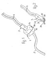
- a plug connection couples a first two-core cable 2, leading to a power source, with a second, two-wire cable 4 to which a lamp, not shown connected.
- the cable 2 is in a first embodiment 1 connected to a socket 1, which consists of an upper part 1e and a lower part 1d.
- a plug 3 is inserted, the with the cable 4 is connected.
- Between upper part 1e and lower part 1d runs a parting plane 1m.
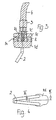
- the plug 3 has opposite sides Contact elements designed as flat contact tabs 3a and 3b on, each housed in a recess 3e and 3f are. Between the flat contact tabs 3a and 3b the plug 3 is penetrated by a slot 3c.
- the Slot 3c protrudes from its in the direction of insertion free end face deeper into the connector 3 than that Cutouts 3e and 3f.
- the bottom of the slot 3c forms a counter surface 3d for an end surface 1b of a partition 1a of the socket 1.
- the partition 1a is in the upper part 1e of the socket 1 provided and penetrates its receiving opening 1c for the Connector 3.
- the lower part 1d two locking lugs 1k, which in the upper part 1e by means of openings overlap formed locking springs 1l.
- the latches 1k and detent springs 1l become the upper part 1e and Lower part 1d in the parting plane 1m firmly pressed together.
- Knife contact tabs 1f and 1g provided in protrude the receiving opening 1c.
- contact surfaces 1h and 1i are formed on the knife contact tabs 1f and 1g.
- the contact surfaces 1h and 1i point inwards and are facing each other.
- the Socket 1 protrudes the partition 1a of the upper part 1e to Partition plane 1m between the knife contact tabs 1f and 1g.
- run-in slopes In and 10 are provided, that make it easier to insert the plug 3 into the socket 1.
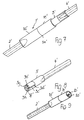
- the invention are both a plug 3 'and a socket 1 'executed circular cylindrical, the Outside diameter of the plug 3 'the maximum possible value for laying the luminaire connection.
- a cable 4 ' is inserted into the rear of the plug 3'.
- the socket 1 ' includes with its plug 3 'opposite end of a cable 2'.
- the socket 1 ' has an upper part 1e 'and a lower part 1d', which in one Lay the parting line 1m 'together.
- the connector 3 'shown in FIGS. 8 and 8a has two parallel to each other in the direction of insertion with their one end in the connector 3 'embedded contact pins 3g and 3h.
- the contact pins 3g and 3h are with their in the plug 3 'embedded end on strands 4a and 4b of the cable 4' connected.
- a slot 3c ' is provided which is the free end of the plug 3 'penetrated between the contact pins 3g and 3h.
- the free end of the contact pins 3g and 3h is of recesses 3e 'and 3f' surrounded, which are open to the slot 3c '.
- the bottom of the slot 3c 'again forms a counter surface 3d 'for contacting an end face 1b' of a partition 1a 'in the socket 1'.
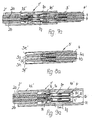
- the upper part 1e 'of the socket 1' has two through holes 1t and 1u, plugged into the two sockets 1p and 1q are.
- the sockets 1p and 1q are at one end with strands 2a and 2b of the one passed through the lower part 1d ' Cable 2 'connected. Point at their other end the sockets 1p and 1q constrictions, the contact surfaces Form 1h 'and 1i' for the contact pins 3g and 3h.
- the through holes 1t and 1u protrude from the sockets 1p and 1q.
- the through holes 1t and 1u are annular Nut 1r enclosed, in which the recesses 3e 'and 3f 'receiving area of the plug 3' is inserted.
- the upper part 1e ' At its end opposite the receiving opening 1c ' the upper part 1e 'has a reduced diameter area 1s on, with which the upper part 1e 'firmly into the lower part 1d 'is inserted, which is the connection between cables 2 'and the sockets 1p and 1q before external contact, as well as that Cable 2 'protects against kink loads.
- the partitions protrude with their end faces facing in the insertion direction an imaginary one running transverse to the direction of insertion Plane through the points of contact between the contact elements the socket on the one hand and the plug on the other runs and is defined. Are points of contact those points where when plugging together the first Contact between the contact elements of the different Plug connection elements come about.
- This Training already extends the air and creepage distances before contacting.
- the face of the partition hurries in relation to the imaginary transverse plane by an amount to create the necessary air and creepage distances sufficient, for example by about 3 mm.
Landscapes
- Connector Housings Or Holding Contact Members (AREA)
- Arrangement Of Elements, Cooling, Sealing, Or The Like Of Lighting Devices (AREA)
- Details Of Connecting Devices For Male And Female Coupling (AREA)
Description
- Figur 1 -
- eine perspektivische Darstellung der geschlossenen Steckerverbindung in einer ersten Ausführungsform;
- Figur 2 -
- eine perspektivische Darstellung des Steckers der Steckerverbindung nach Fig. 1;
- Figur 3 -
- einen Längsschnitt durch die Steckerverbin- dung entlang der Schnittebene III -III in Fig. 4;
- Figur 4 -
- eine Ansicht der Steckverbindung in Fig. 3 von unten;
- Figur 5 -
- eine perspektivische Darstellung des Unterteils der Steckdose der Steckerverbindung nach Fig. 1;
- Figur 6 -
- eine perspektivische Darstellung der Gerätesteckdose nach Fig. 1;
- Figur 7 -
- eine perspektivische Darstellung einer Stekkerverbindung in einer zweiten Ausführungsform;
- Figur 7a -
- einen Längsschnitt durch die Steckerverbindung nach Fig. 7;
- Figur 8 -
- eine perspektivische Darstellung des Steckers der Steckerverbindung nach Fig. 7;
- Figur 8a -
- einen Längsschnitt durch den Stecker nach Fig. 8;
- Figur 9 -
- eine perspektivische Ansicht der Steckdose nach Fig. 7;
- Figur 9a -
- einen Längsschnitt durch die Steckdose nach Fig. 9.
Claims (23)
- Steckerverbindung für Möbelleuchten mit einer ein Steckdosengehäuse aufweisenden Steckdose (1; 1'), die mit einem ersten Kabel (2; 2') verdrahtet ist und mit einem in die Steckdose (1; 1') einsteckbaren, ein Steckergehäuse aufweisenden Stecker (3; 3'), der mit einem zweiten Kabel (4; 4') verdrahtet ist, mit in der Einsteckposition aneinanderliegenden, jeweils paarweise vorgesehenen, beabstandeten Kontaktelementen, wobei die Steckdose (1; 1') eine parallel zu ihren Kontaktelementen zwischen diesen verlaufende Trennwand (1a; 1a') aufweist, die in Einsteckposition zwischen die Kontaktelemente des Stekkers (3; 3') eintaucht, wobei die Kontaktelemente des Steckers (3; 3') von Bereichen des Steckegehäuses umgriffen werden und die Trennwand (1a; 1a') in der Einsteckposition zwischen den Kontaktelementen des Steckers (3; 3') verläuft, wobei ferner die Trennwand in Einsteckrichtung vorragt gegenüber einer quer zur Trennwand verlaufenden Ebene durch die Berührungspunkte zwischen den Kontaktelementen der Steckdose (1; 1') einerseits und des Steckers (3; 3') andererseits, wobei die Berührungspunkte diejenigen Punkte sind, bei denen beim Zusammenstecken der erste Kontakt zwischen den Kontaktelementen von Steckdose und Stecker zustande kommt,
dadurch gekennzeichnet, daß das Steckergehäuse eine zylindrische Hüllfläche aufweist, innerhalb deren die Kontaktelemente des Stekkers (3; 3') liegen, und die Trennwand (1a; 1a') in der Einsteckposition in einen das Steckergehäuse quer durchsetzenden Schlitz (3c; 3c') eintaucht, dessen in Einschubrichtung des Steckers (3; 3') gemessene Tiefe größer ist als die in gleicher Richtung gemessene Tiefe von Aussparungen (3e; 3f; 3e'; 3f'), welche die freien Flächen der Kontaktelemente (3a; 3b; 3g; 3h) des Steckers (3; 3') in Einschubrichtung begrenzen. - Steckerverbindung nach Anspruch 1,
dadurch gekennzeichnet, daß die Trennwand (1a; 1a') mit ihrer Stirnfläche (1b; 1b') in der Einsteckposition an einer Gegenfläche (3d; 3d') des Steckergehäuses anliegt. - Steckerverbindung nach Anspruch 1 oder 2,
dadurch gekennzeichnet, daß das zweite Kabel (4; 4') mit der Möbelleuchte verbunden ist. - Steckerverbindung nach einem oder mehreren der Ansprüche 1 bis 3,
dadurch gekennzeichnet, daß die Kontaktelemente des Steckers (3; 3') teilweise in das Material des Steckergehäuses eingebettet sind. - Steckerverbindung nach einem oder mehreren der Ansprüche 1 bis 4,
dadurch gekennzeichnet, daß die Kontaktelemente des Steckers (3') Kontaktstifte (3g; 3h) und die Kontaktelemente der Steckdose (1) radial elastische, die Kontaktstifte (3g; 3h) mit Vorspannung umgreifende Buchsen (1p; 1q) sind. - Steckerverbindung nach einem oder mehreren der Ansprüche 1 bis 4,
dadurch gekennzeichnet, daß die Kontaktelemente des Steckers (3) Flachkontaktlaschen (3a; 3b) sind, die teilweise mit ihren Seitenflächen in das Material des Steckergehäuses eingebettet sind und radial zu gegenüberliegenden Seiten auswärts weisende, freiliegende Kontaktflächen aufweisen. - Steckerverbindung nach Anspruch 6,
dadurch gekennzeichnet, daß die freiliegenden Kontaktflächen von einander gegenüberliegenden bis in die Außenkontur des Steckergehäuses sich erstreckenden Aussparungen (3e; 3f) des Stekkergehäuses begrenzt sind. - Steckerverbindung nach Anspruch 6,
dadurch gekennzeichnet, daß die Kontaktelemente der Steckdose (1) radial federnd ausgebildete Messerkontaktlaschen (1f; 1g) sind, zwischen deren nach innen weisenden und einander zugewandten Kontaktflächen (1h; 1i) die Trennwand (1a) der Steckdose (1) angeordnet ist. - Steckerverbindung nach einem oder mehreren der Ansprüche 1 bis 8,
dadurch gekennzeichnet, daß die Steckdose (1) ein die Kontaktelemente aufweisendes Unterteil (1d) und ein die Trennwand (1a) aufweisendes Oberteil (1e) aufweist. - Steckerverbindung nach Anspruch 9,
dadurch gekennzeichnet, daß Oberteil (1e) und Unterteil (1d) über Rastelemente (1l, 1k) miteinander verbunden sind. - Steckerverbindung nach Anspruch 9 oder 10,
dadurch gekennzeichnet, daß die Kontaktelemente der Steckdose (1) an der Trennebene (1m) über das Gehäusematerial des Unterteils (1d) vorragen. - Steckerverbindung nach einem oder mehreren der Ansprüche 9 bis 11,
dadurch gekennzeichnet, daß die Trennwand (1a) sich bis zur Trennebene (1m) erstreckt. - Steckerverbindung nach Anspruch 8,
dadurch gekennzeichnet, daß an den Messerkontaktlaschen (1g; 1f) Einlaufschrägen (1n; 1o) vorgesehen sind. - Steckerverbindung nach einem oder mehreren der Ansprüche 9 bis 13,
dadurch gekennzeichnet, daß das Oberteil (1e') der Steckdose (1') zwei Durchgangsbohrung (1t; 1u) aufweist, in die jeweils eine Buchse (1p; 1q) klemmend einsteckbar ist. - Steckerverbindung nach Anspruch 14,
dadurch gekennzeichnet, daß das Oberteil (1e') eine Aufnahmeöffnung (1c') aufweist, von dessen Boden sich eine die Buchsen (1p; 1q) teilweise umgebende ringförmige Nut (1r) in axialer Richtung in das Steckdosengehäuse erstreckt. - Steckerverbindung nach Anspruch 5,
dadurch gekennzeichnet, daß die Trennwand (1a') in die Aufnahmeöffnung (1c') hineinragt. - Steckerverbindung nach Anspruch 5,
dadurch gekennzeichnet, daß die Kontaktflächen (1h'; 1i') durch Einschnürungen an den Buchsen (1p; 1q) gebildet sind. - Steckerverbindung nach einem oder mehreren der Ansprüche 9 bis 17,
dadurch gekennzeichnet, daß das Oberteil (1e') an seinem der Aufnahmeöffnung (1c') gegenüberliegenden Ende einen reduzierten Durchmesserbereich (1s) aufweist, mit dem es in eine Öffnung des Unterteils (1d') eingepreßt ist. - Steckerverbindung nach Anspruch 14,
dadurch gekennzeichnet, daß die Durchgangsbohrungen (1t; 1u) die freien Enden der Buchsen (1p; 1q) überragen. - Steckerverbindung nach Anspruch 5,
dadurch gekennzeichnet, daß die Kontaktstifte (3g; 3h) teilweise in die an dem freien Ende des Steckers vorgesehenen Aussparungen (3e'; 3f') hineinragen, die zum Schlitz 3c' hin offen sind. - Steckerverbindung nach einem oder mehreren der Ansprüche 1 bis 20,
dadurch gekennzeichnet, daß die Gehäuse der Steckdose (1; 1') und des Steckers (3; 3') Kunststoffspritzgußteile sind. - Steckerverbindung nach einem oder mehreren der Ansprüche 1 bis 21,
dadurch gekennzeichnet, daß der Durchmesser der kreiszylindrischen Hüllfläche des Steckers (3; 3') kleiner als 8 mm ist. - Steckerverbindung nach Anspruch 22,
dadurch gekennzeichnet, daß der Durchmesser der kreiszylindrischen Hüllfläche des Steckerteils 7 mm beträgt.
Applications Claiming Priority (2)
| Application Number | Priority Date | Filing Date | Title |
|---|---|---|---|
| DE10058615 | 2000-11-25 | ||
| DE10058615A DE10058615A1 (de) | 2000-11-25 | 2000-11-25 | Steckerverbindung für Möbelleuchten |
Publications (3)
| Publication Number | Publication Date |
|---|---|
| EP1209767A2 EP1209767A2 (de) | 2002-05-29 |
| EP1209767A3 EP1209767A3 (de) | 2002-06-12 |
| EP1209767B1 true EP1209767B1 (de) | 2003-06-04 |
Family
ID=7664677
Family Applications (1)
| Application Number | Title | Priority Date | Filing Date |
|---|---|---|---|
| EP01127920A Expired - Lifetime EP1209767B1 (de) | 2000-11-25 | 2001-11-23 | Steckerverbindung für Möbelleuchten |
Country Status (3)
| Country | Link |
|---|---|
| EP (1) | EP1209767B1 (de) |
| AT (1) | ATE242557T1 (de) |
| DE (2) | DE10058615A1 (de) |
Cited By (1)
| Publication number | Priority date | Publication date | Assignee | Title |
|---|---|---|---|---|
| DE10341718A1 (de) * | 2003-09-10 | 2005-04-14 | E-lektra Gesellschaft für elektrotechnische Geräte mbH | Elektrische Mehrfachkupplung |
Family Cites Families (6)
| Publication number | Priority date | Publication date | Assignee | Title |
|---|---|---|---|---|
| BE537458A (de) * | 1954-06-01 | |||
| US3188597A (en) * | 1962-07-02 | 1965-06-08 | Gen Electric | Terminal device |
| US3311763A (en) * | 1963-07-15 | 1967-03-28 | Sunbeam Corp | Electric shaver |
| JPH09274960A (ja) * | 1996-04-03 | 1997-10-21 | Kokusai Denshin Denwa Co Ltd <Kdd> | コネクタ装置 |
| JPH09293558A (ja) * | 1996-04-26 | 1997-11-11 | Sumitomo Wiring Syst Ltd | 線状体結合部品の保護カバー |
| JPH11135195A (ja) * | 1997-10-31 | 1999-05-21 | Sumitomo Wiring Syst Ltd | 2極コネクタ |
-
2000
- 2000-11-25 DE DE10058615A patent/DE10058615A1/de not_active Withdrawn
-
2001
- 2001-11-23 AT AT01127920T patent/ATE242557T1/de active
- 2001-11-23 DE DE50100289T patent/DE50100289D1/de not_active Expired - Lifetime
- 2001-11-23 EP EP01127920A patent/EP1209767B1/de not_active Expired - Lifetime
Cited By (1)
| Publication number | Priority date | Publication date | Assignee | Title |
|---|---|---|---|---|
| DE10341718A1 (de) * | 2003-09-10 | 2005-04-14 | E-lektra Gesellschaft für elektrotechnische Geräte mbH | Elektrische Mehrfachkupplung |
Also Published As
| Publication number | Publication date |
|---|---|
| DE10058615A1 (de) | 2002-05-29 |
| DE50100289D1 (de) | 2003-07-10 |
| EP1209767A3 (de) | 2002-06-12 |
| ATE242557T1 (de) | 2003-06-15 |
| EP1209767A2 (de) | 2002-05-29 |
Similar Documents
| Publication | Publication Date | Title |
|---|---|---|
| DE602004011002T2 (de) | Wasserdichter Verbinder und Zusammenbauverfahren | |
| DE19808087C2 (de) | Elektrischer Koaxialsteckverbinder | |
| EP3735722B1 (de) | Kontaktträger und steckverbinder für eine geschirmte hybride kontaktanordnung | |
| EP0092243B1 (de) | Leuchte | |
| DE2549597A1 (de) | Kupplungsanordnung fuer verbindbare enden elektrischer leitungen | |
| DE1141355B (de) | Elektrische Verbinder | |
| EP1081789A2 (de) | Elektrischer Steckverbinder | |
| EP1538708B1 (de) | Ladesteckverbindersatz mit Adapter | |
| DE2806496A1 (de) | Mehrfach-steckverbinder | |
| DE68909735T2 (de) | Elektrische Testanordnung. | |
| DE10045024A1 (de) | Lichtwellenleiterbuchse und Lichtwellenleiterstecker sowie Lichtwellenleiterbuchsen-Anordnung | |
| DE202004010179U1 (de) | Mehrzweckstecker | |
| EP1209767A2 (de) | Steckerverbindung für Möbelleuchten | |
| DE69905881T2 (de) | Modularer elektrischer steckverbinder | |
| DE19525801C2 (de) | Vorrichtung zum elektrisch leitenden Verbinden von zwei elektrischen Leitungen | |
| EP2192658B1 (de) | Verbindungseinrichtung | |
| DE2646063A1 (de) | Kupplungsgehaeuse fuer verbinder | |
| DE102004004203A1 (de) | Verbindungselement für das elektrisch leitende Verbinden mit dem Lampensockel eines Hauptscheinwerfers | |
| DE102005021375B4 (de) | Steckverbinder, insbesondere für Airbag-Zündsysteme | |
| EP1569288B1 (de) | Ladesteckverbindersatz mit Gehäuseadapter | |
| EP1094557A2 (de) | Platinen-Hochstrom-Steckvorrichtung | |
| DE2723725B2 (de) | Elektrische Mehrfachkupplung | |
| DE19816765C2 (de) | Fassung für Leuchtstofflampen | |
| DE202007011724U1 (de) | Elektrischer Verbindungsbausatz zum Herstellen eines Verkabelungsbaumes | |
| DE1905044A1 (de) | Vielfachsteckverbindung fuer elektrische Leitungen |
Legal Events
| Date | Code | Title | Description |
|---|---|---|---|
| PUAI | Public reference made under article 153(3) epc to a published international application that has entered the european phase |
Free format text: ORIGINAL CODE: 0009012 |
|
| PUAL | Search report despatched |
Free format text: ORIGINAL CODE: 0009013 |
|
| AK | Designated contracting states |
Kind code of ref document: A2 Designated state(s): AT BE CH CY DE DK ES FI FR GB GR IE IT LI LU MC NL PT SE TR |
|
| AX | Request for extension of the european patent |
Free format text: AL;LT;LV;MK;RO;SI |
|
| AK | Designated contracting states |
Kind code of ref document: A3 Designated state(s): AT BE CH CY DE DK ES FI FR GB GR IE IT LI LU MC NL PT SE TR |
|
| AX | Request for extension of the european patent |
Free format text: AL;LT;LV;MK;RO;SI |
|
| RIC1 | Information provided on ipc code assigned before grant |
Free format text: 7H 01R 24/04 A, 7H 01R 24/06 B, 7H 01R 24/04 J, 7H 01R 103:00 J, 7H 01R 24/06 K, 7H 01R 103:00 K |
|
| 17P | Request for examination filed |
Effective date: 20020712 |
|
| 17Q | First examination report despatched |
Effective date: 20020920 |
|
| GRAH | Despatch of communication of intention to grant a patent |
Free format text: ORIGINAL CODE: EPIDOS IGRA |
|
| AKX | Designation fees paid |
Designated state(s): AT BE CH CY DE DK ES FI FR GB GR IE IT LI LU MC NL PT SE TR |
|
| RAP1 | Party data changed (applicant data changed or rights of an application transferred) |
Owner name: E-LEKTRA GESELLSCHAFT FUER ELEKTROTECHNISCHE GERAE |
|
| GRAH | Despatch of communication of intention to grant a patent |
Free format text: ORIGINAL CODE: EPIDOS IGRA |
|
| GRAA | (expected) grant |
Free format text: ORIGINAL CODE: 0009210 |
|
| RBV | Designated contracting states (corrected) |
Designated state(s): AT BE CH DE FR GB IT LI |
|
| AK | Designated contracting states |
Designated state(s): AT BE CH DE FR GB IT LI |
|
| REG | Reference to a national code |
Ref country code: GB Ref legal event code: FG4D Free format text: NOT ENGLISH |
|
| REG | Reference to a national code |
Ref country code: CH Ref legal event code: EP Ref country code: CH Ref legal event code: NV Representative=s name: SCHMAUDER & PARTNER AG PATENTANWALTSBUERO |
|
| GBT | Gb: translation of ep patent filed (gb section 77(6)(a)/1977) | ||
| REG | Reference to a national code |
Ref country code: IE Ref legal event code: FG4D Free format text: GERMAN |
|
| REF | Corresponds to: |
Ref document number: 50100289 Country of ref document: DE Date of ref document: 20030710 Kind code of ref document: P |
|
| REG | Reference to a national code |
Ref country code: IE Ref legal event code: FD4D |
|
| ET | Fr: translation filed | ||
| PLBE | No opposition filed within time limit |
Free format text: ORIGINAL CODE: 0009261 |
|
| STAA | Information on the status of an ep patent application or granted ep patent |
Free format text: STATUS: NO OPPOSITION FILED WITHIN TIME LIMIT |
|
| 26N | No opposition filed |
Effective date: 20040305 |
|
| REG | Reference to a national code |
Ref country code: CH Ref legal event code: PCAR Free format text: SCHMAUDER & PARTNER AG PATENT- UND MARKENANWAELTE VSP;ZWAENGIWEG 7;8038 ZUERICH (CH) |
|
| REG | Reference to a national code |
Ref country code: FR Ref legal event code: PLFP Year of fee payment: 15 |
|
| REG | Reference to a national code |
Ref country code: FR Ref legal event code: PLFP Year of fee payment: 16 |
|
| REG | Reference to a national code |
Ref country code: FR Ref legal event code: PLFP Year of fee payment: 17 |
|
| PGFP | Annual fee paid to national office [announced via postgrant information from national office to epo] |
Ref country code: IT Payment date: 20201130 Year of fee payment: 20 Ref country code: FR Payment date: 20201119 Year of fee payment: 20 Ref country code: GB Payment date: 20201106 Year of fee payment: 20 Ref country code: DE Payment date: 20201125 Year of fee payment: 20 Ref country code: AT Payment date: 20201117 Year of fee payment: 20 Ref country code: CH Payment date: 20201124 Year of fee payment: 20 |
|
| PGFP | Annual fee paid to national office [announced via postgrant information from national office to epo] |
Ref country code: BE Payment date: 20201119 Year of fee payment: 20 |
|
| REG | Reference to a national code |
Ref country code: DE Ref legal event code: R071 Ref document number: 50100289 Country of ref document: DE |
|
| REG | Reference to a national code |
Ref country code: GB Ref legal event code: PE20 Expiry date: 20211122 |
|
| REG | Reference to a national code |
Ref country code: BE Ref legal event code: MK Effective date: 20211123 |
|
| REG | Reference to a national code |
Ref country code: AT Ref legal event code: MK07 Ref document number: 242557 Country of ref document: AT Kind code of ref document: T Effective date: 20211123 |
|
| PG25 | Lapsed in a contracting state [announced via postgrant information from national office to epo] |
Ref country code: GB Free format text: LAPSE BECAUSE OF EXPIRATION OF PROTECTION Effective date: 20211122 |