EP1209783A2 - Module laser à semiconducteur et amplificateur raman - Google Patents
Module laser à semiconducteur et amplificateur raman Download PDFInfo
- Publication number
- EP1209783A2 EP1209783A2 EP01309303A EP01309303A EP1209783A2 EP 1209783 A2 EP1209783 A2 EP 1209783A2 EP 01309303 A EP01309303 A EP 01309303A EP 01309303 A EP01309303 A EP 01309303A EP 1209783 A2 EP1209783 A2 EP 1209783A2
- Authority
- EP
- European Patent Office
- Prior art keywords
- semiconductive
- semiconductive laser
- laser module
- optical
- light
- Prior art date
- Legal status (The legal status is an assumption and is not a legal conclusion. Google has not performed a legal analysis and makes no representation as to the accuracy of the status listed.)
- Withdrawn
Links
Images


Classifications
-
- G—PHYSICS
- G02—OPTICS
- G02B—OPTICAL ELEMENTS, SYSTEMS OR APPARATUS
- G02B6/00—Light guides; Structural details of arrangements comprising light guides and other optical elements, e.g. couplings
- G02B6/24—Coupling light guides
- G02B6/42—Coupling light guides with opto-electronic elements
- G02B6/4201—Packages, e.g. shape, construction, internal or external details
- G02B6/4204—Packages, e.g. shape, construction, internal or external details the coupling comprising intermediate optical elements, e.g. lenses, holograms
- G02B6/4215—Packages, e.g. shape, construction, internal or external details the coupling comprising intermediate optical elements, e.g. lenses, holograms the intermediate optical elements being wavelength selective optical elements, e.g. variable wavelength optical modules or wavelength lockers
-
- G—PHYSICS
- G02—OPTICS
- G02B—OPTICAL ELEMENTS, SYSTEMS OR APPARATUS
- G02B6/00—Light guides; Structural details of arrangements comprising light guides and other optical elements, e.g. couplings
- G02B6/24—Coupling light guides
- G02B6/42—Coupling light guides with opto-electronic elements
- G02B6/4201—Packages, e.g. shape, construction, internal or external details
- G02B6/4286—Optical modules with optical power monitoring
-
- H—ELECTRICITY
- H01—ELECTRIC ELEMENTS
- H01S—DEVICES USING THE PROCESS OF LIGHT AMPLIFICATION BY STIMULATED EMISSION OF RADIATION [LASER] TO AMPLIFY OR GENERATE LIGHT; DEVICES USING STIMULATED EMISSION OF ELECTROMAGNETIC RADIATION IN WAVE RANGES OTHER THAN OPTICAL
- H01S5/00—Semiconductor lasers
- H01S5/10—Construction or shape of the optical resonator, e.g. extended or external cavity, coupled cavities, bent-guide, varying width, thickness or composition of the active region
- H01S5/14—External cavity lasers
- H01S5/141—External cavity lasers using a wavelength selective device, e.g. a grating or etalon
-
- G—PHYSICS
- G02—OPTICS
- G02B—OPTICAL ELEMENTS, SYSTEMS OR APPARATUS
- G02B6/00—Light guides; Structural details of arrangements comprising light guides and other optical elements, e.g. couplings
- G02B6/24—Coupling light guides
- G02B6/42—Coupling light guides with opto-electronic elements
- G02B6/4201—Packages, e.g. shape, construction, internal or external details
- G02B6/4204—Packages, e.g. shape, construction, internal or external details the coupling comprising intermediate optical elements, e.g. lenses, holograms
- G02B6/4207—Packages, e.g. shape, construction, internal or external details the coupling comprising intermediate optical elements, e.g. lenses, holograms with optical elements reducing the sensitivity to optical feedback
-
- H—ELECTRICITY
- H01—ELECTRIC ELEMENTS
- H01S—DEVICES USING THE PROCESS OF LIGHT AMPLIFICATION BY STIMULATED EMISSION OF RADIATION [LASER] TO AMPLIFY OR GENERATE LIGHT; DEVICES USING STIMULATED EMISSION OF ELECTROMAGNETIC RADIATION IN WAVE RANGES OTHER THAN OPTICAL
- H01S3/00—Lasers, i.e. devices using stimulated emission of electromagnetic radiation in the infrared, visible or ultraviolet wave range
- H01S3/30—Lasers, i.e. devices using stimulated emission of electromagnetic radiation in the infrared, visible or ultraviolet wave range using scattering effects, e.g. stimulated Brillouin or Raman effects
- H01S3/302—Lasers, i.e. devices using stimulated emission of electromagnetic radiation in the infrared, visible or ultraviolet wave range using scattering effects, e.g. stimulated Brillouin or Raman effects in an optical fibre
Definitions
- the present invention relates to a Raman amplifier for use in optical communication, and a semiconductive laser module and a laser unit for use as a pumping light source for the Raman amplifier.
- EDFA Erbium doped optical fiber amplifier
- the EDFA has a practical gain wavelength bandwidth ranging simply from 1530 nm to 1610 nm.
- the EDFA has a wavelength dependency in the gain to give rise to a difference in gain depending on the wavelength of signal light, in application to wavelength division multiplexed light.
- the Raman amplification In advancement of the DWDM (dense wavelength division multiplexing), the Raman amplification has gathered an increased expectancy as an amplification system with a wider band than the EDFA.
- the Raman amplification is an optical signal amplification method using the following phenomenon.
- strong light prumping light
- the gain When strong light (pumping light) is input to an optical fiber, the gain has a peak shifted by an induced Raman scattering from the pumping light's wavelength, toward the longer wavelength side, at approx. 100 nm or near therefrom (a frequency lower by approx. 13 THz on assumption of the use of pumping light in a 1400 nm band). If signal light of a wavelength bandwidth in which the above-noted gain is obtainable is input to the optical fiber thus pumped, then the signal light is amplified.
- the Raman amplification has such a feature that the wavelength for gain to be generated can be arbitrarily changed by varying the wavelength of pumping light, the gain (Raman gain) is small. Further, because the gain to be used is shifted from the pumping light's wavelength by a predetermined wavelength (Raman shift) toward the longer wavelength side, the variation in wavelength of pumping light provides a variation in the wavelength for the gain to be generated, causing the amplification characteristic of signal light to be varied. Therefore, as the pumping light source to be used for Raman amplification, there is employed a high-output semiconductive laser module having a wavelength stabilized by a fiber grating.
- the EDFA has a practical gain wavelength bandwidth from 1530 nm to 1610 nm or near, but the Raman amplification is almost free from restriction to the wavelength bandwidth (while practically a range of 1300 nm to 1650 nm is considered to be used, and the wavelength bandwidth of pumping light ranges from 1200 nm to 1550 nm).
- the wavelength of pumping light to be input to an optical fiber is changed, the gain to appear is shifted from the pumping light's wavelength by a predetermined wavelength toward the longer wavelength side, to allow the amplification gain to be obtained at an arbitrary wavelength. Therefore, in the WDM (wavelength division multiplexing), the number of channels of signal light can be yet increased.
- the above-noted gain becomes a distribution gain having a wavelength distribution, for example, as a distribution with a width of 20 nm or near.
- a variety of wavelengths of pumping light are multiplexed to properly adjust wavelengths of respective pumping lasers, outputs of the same and the like.
- an existing optical fiber for communication can be used as an amplification medium.
- the Raman gain in use thereof is as small as approx. 3dB for a pumping light input of 100 mW. It therefore is necessary to obtain strong pumping light by multiplexing. It is common to multiplex pumping light to a range from 500 mW to 1 W or near in total.
- a semiconductive laser module configured as follows:
- a first semiconductive laser module comprises a semiconductive laser module having a semiconductive laser device, a cavity formed with at least one light feedback means included, and an optical fiber located at a front side of the cavity, wherein an optical filter for transmitting light of wavelength within a predetermined range is disposed in the cavity.
- the above-noted semiconductive laser module additionally has a collimator and a focusing lens for coupling light emitted from the semiconductive laser device with the optical fiber, and the optical filter is disposed between the collimator and the focusing lens.
- a laser unit comprises a plurality of first or second semiconductive laser modules, and a polarization beam combiner for polarization-combining the light emitted from the plurality of semiconductive laser modules.
- a Raman amplifier according to the present invention has a pumping light source comprising one of the first or second semiconductive laser module and the laser unit.
- the laser module with fiber grating having been used as an pumping light source for Raman amplifier has the following problems:
- a semiconductive laser module, a laser unit, and a Raman amplifier are adapted to meet the following required characteristics (1) to (7).
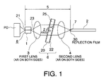
- Fig. 1 shows a first embodiment of semiconductive laser module of the present invention.
- a cavity 5 is configured between a reflective film 21 formed on a rear end face 8 of a semiconductive laser device 1 and an input end face 7 (exposed face) of an optical fiber 2 or a low-reflection film 30 formed on the input end face 7.
- the semiconductive laser module has a photo diode (PD) 40 for monitoring, the semiconductive laser device 1, a first lens (collimator) 3 for collimated beam from the semiconductive laser device 1, an optical filter (BPF) 6 for transmitting light of wavelength simply within a predetermined range, a second lens (focusing lens) 4 for focusing collimated light from the collimator 3, and the optical fiber 2 for transmitting light focused by the focusing lens 4, arrayed in serial in this sequence.
- PD photo diode
- BPF optical filter
- BPF optical filter
- focusing lens for focusing collimated light from the collimator 3
- the optical fiber 2 for transmitting light focused by the focusing lens 4, arrayed in serial in this sequence.
- the semiconductive laser device 1 has on the rear end face 8 thereof the reflection film (HR film) 21 as a coating with a reflectivity as high as 90% or near, and on a front end face 10 thereof a low-reflection film (AR film) 23 as a coating with a low reflectivity.
- HR film reflection film
- AR film low-reflection film
- the reflectivity of the AR film 23 is set to a low value of, for example, 5% or less, and preferably 1% or less, or more preferably 0.1% or less.
- the HR film 21 of the semiconductive laser device 1 is optimally designed in accordance with a light receiving condition of the PD 40. It however is preferable to provide countermeasures against return light, such as setting a light receiving surface of the PD 40 in oblique position, not to make a cavity between the HR film 21 and the PD 40.
- the first lens 3, as well as the second lens 4 has an AR film as a coating thereon with a reflectivity of 0.5% or less .
- These lenses may each preferably be one of aspherical lens, ball lens, reflectivity distributed lens, flat convex lens, and the like.
- the optical fiber 2 includes a PMF in addition to a single mode optical fiber (SMF).
- polarization holding axes (slow axis, fast axis ) of the PMF may be set in the direction of a polarization plane of laser beam, to allow the laser beam to be transmitted, as it is linearly polarized, or may be set at a predetermined angle, for example at 45 degrees, relative to the direction of the polarization plane, for effecting a depolarization to reduce the DOP of laser beam.
- the input end face 7 of the optical fiber 2 is formed as a reflection end face with a coated low-reflection film 30 having, to the laser beam, a reflectivity within a range approximately under 5% and above approx. 0.5% over a wavelength range of ⁇ 5 nm or more about a center thereof to be, for example, a light emission wavelength or lasing wavelength of the laser beam.
- the input end face 7 of the optical fiber 2 may not be provided with the low-reflection film 30, but may have a polished surface or cut face thereof exposed to make use of Fresnel reflection at the exposed face.
- the optical fiber 2 is enabled to have high-output light input thereto, allowing a lasing at the cavity 5.
- the PD 40 monitors output light behind the semiconductive laser device 1.
- Output of the semiconductive laser module is automatically controlled so that the optical output to be detected by the PD 40 remains constant.
- the optical filter 6 is configured with a substrate 20, such as made of BK7 or quartz, an optical filter film 25 formed on the rear surface of the substrate made of a dielectric multi-layered filter transmitting a desired wavelength of light, and an AR film 22 formed on the front surface.
- the AR film 22 is designed so as to have an as better transmittance as possible.
- the optical filter 6 is inclined to be disposed, at a predetermined inclination angle (for example, 1° ⁇ 5°) relative to the optical axis of light to be propagated between the first lens 3 and the second lens 4.
- the optical filter 6 may be disposed anywhere in the cavity 5, it is preferable for the filter to dispose between the first lens 3 as a collimator and the second lens 4 as a focusing lens, where the input angle to the optical filter 6 is constant at any point on a section of the beam.
- Respective films in the present embodiment may be formed with a predetermined number of laminated cavities made for example of Ta 2 O 5 /SiO 2 , TiO 2 /SiO 2 , or Al 2 O 3 /SiO 2 , allowing associated items such as the number of laminations to be designed for a suitable setting, such as of reflection bandwidth or transmission bandwidth, reflectivity or transmittance, or spectral configuration.
- the optical filter film 25 has a substantially rectangular transmittance spectrum.
- the transmission wavelength bandwidth is 2 nm at half width half maximum.
- the transmission wavelength bandwidth is 3 nm at half width half maximum.
- solid lines, broken lines, and dotted lines represent transmittance spectra when the inclination angle of the optical filter 6 is changed to 0° , 2° , and 4° , respectively. It is shown that, by such changes in inclination angle of the optical filter 6, the transmission spectrum has changed center wavelengths.
- the optical filter film 25 having such a substantially rectangular transmittance spectrum configuration, the spectrum of light to be fed back to the semiconductive laser device 1 is controlled, whereby a multi-mode lasing in a laser beam outputted from the semiconductive laser device 1 is facilitated.
- optical intensity of respective one of the longitudinal modes so as not to exceed an SBS occurrence threshold value, it is then allowed to suppress the occurrence of SBS due to the longitudinal mode. Since a plurality of longitudinal modes are allowed to have high optical intensities distributed thereamong, the optical output as a whole can be high.
- the optical filter 6 allows utilization of the fact that, by rendering larger the inclination angle relative to the optical axis of emitted light from the semiconductive laser device 1, the lasing wavelength is shifted toward the shorter wavelength side, as shown in Fig. 11A and Fig. 11B, so that the lasing wavelength can be tuned by adjustment of the inclination angle.
- the inclination may be in any direction from the position in which light is normally input to the optical filter 6, whereas the polarization dependency disappears if the inclination is parallel or perpendicular to the direction of the polarization plane, so that the occurrence of PDL (polarization dependent loss) can be suppressed even with an inclination at several ten degrees.
- PDL polarization dependent loss
- the thickness of each layer of the optical filter film 25 is controlled so that the transmittance spectrum of light is varied in dependence on the position of transmission of the light at the optical filter film 25 in the optical filter 6, and then the optical filter 6 is moved substantially in the perpendicular direction to the optical axis, to change the position at which light is input to the optical filter 6, thereby changing the transmission position of light in the optical filter film 25, thus tuning the lasing wavelength.
- the optical filter 6 is mounted on a thermomodule (for example, a Peltier module, not shown) on which the semiconductive laser device 1 is mounted, so that, by the placement together with the semiconductive laser device 1 under temperature control by the Peltier element, the wavelength shift as well as disorder of waveform is eliminated, having a stable characteristic.
- the optical filter 6 may be mounted on a module else than the thermomodule on which the semiconductive laser device 1 mounted.
- emitted light from the front end face 10 of the semiconductive laser device 1 is collimated by the first lens 3, has wavelengths selected by the optical filter 6, is focused by the second lens 4, and is reflected in part by the input end face 7 of the optical fiber 2, to be optically fed back to the semiconductive laser device 1, via a reverse route. The remainder of light is input to the optical fiber 2, where it is transmitted.
- the optical feedback and reciprocation in the cavity 5 there is caused a lasing in the semiconductive laser device 1, which outputs a laser beam.
- Mere desired wavelengths of light are selected by the optical filter 6, to be optically fed back to the semiconductive laser device 1, whereby the laser beam has a stabilized wavelength characteristics.
- the laser beam is transmitted by the optical fiber 2, to be used for a desired purpose.
- the cavity length can be set short (for example, 20 nm and under), allowing for prevention of a deterioration that the noise characteristic might have suffered in a predetermined frequency bandwidth due to a longer cavity.
- the spectrum width of light can be compressed narrow, allowing for an enhanced optical output and for a good wavelength stability.
- the transmission spectrum of the optical filter 6 is set to a predetermined configuration, whereby output light from the semiconductive laser device 1 is allowed to be multi-mode, so that the occurrence of SBS can be prevented, with a maintained high optical output.
- the multi-mode is advantageous also for DOP reduction.
- the semiconductive laser module according to this embodiment is essentially adapted to have necessary characteristics as a pumping light source for Raman amplifiers.
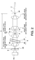
- Fig. 2 shows a second embodiment of semiconductive laser module of the present invention.
- a cavity 5 is configured between a reflection film 26 of a reflective parts 9 and an input end face 7 (exposed face) of an optical fiber 2 or a low-reflection film 30 formed on the input end face 7.
- the semiconductive laser module as a configuration with an optical filter 6 disposed behind a semiconductive laser device 1, has a PD 40, the reflective parts 9, a fourth lens (collimator) 16, the optical filter 6, a third lens (focusing lens) 15, the semiconductive laser device 1, a first lens 3, a second lens 4, and the optical fiber 2, arrayed in serial in this sequence.
- the semiconductive laser device 1 has on a front end face 10 thereof an AR film 34 and on a rear end face 8 thereof an AR film 24, each as a coating thereon.
- the reflectivity of the AR films 24, 34 is, for example, 5% or less, and may preferably be 1% or less, or more preferably 0.1% or less.
- the third lens 15 and the fourth lens 16, as well as the first lens 3 and the second lens 4, are coated at their font and rear surfaces by AR films, whose reflectivity is ,for example, 0.5% or less.
- These lenses also may each preferably be one of aspherical lens, ball lens, reflectivity distributed lens, flat convex lens, and the like, to be selected as necessary.
- the optical filter 6 is configured to be the same as in the first embodiment, except for the disposition between the third lens 15 and the fourth lens 16, and may preferably be temperature-controlled on a thermomodule like the first embodiment.
- emitted light from the rear end face 8 of the semiconductive laser device 1 is collimated by the third lens 15, has wavelengths selected by the optical filter 6, is focused by the fourth lens 16, and is optically fed back by a reflection film 26.
- Emitted light from the front end face 10 of the semiconductive laser device 1 is transmitted via the first lens and the fourth lens, and optically fed back in part at the input end face 7 of the optical fiber 2 to the semiconductive laser device 1, while the remainder is input to the optical fiber 2, where it is transmitted.
- the optical feedback and reciprocation in the cavity 5 there is caused a lasing in the semiconductive laser device 1, which outputs a laser beam.
- Mere desired wavelengths of light are selected by the optical filter 6, to be optically fed back to the semiconductive laser device 1, whereby the laser beam has a stabilized wavelength characteristics.
- the laser beam emitted from the front end face 10 of the semiconductive laser device 1 is transmitted by the optical fiber 2, to be used for a desired purpose.
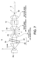
- Fig. 3 shows a third embodiment of semiconductive laser module of the present invention.
- a cavity 5 is configured between a reflection film 26 of a reflective parts 9 and an AR film 34 formed on a front end face 10 of a semiconductive laser device 1.
- the semiconductive laser module according to this embodiment is a little modified in configuration from the semiconductive laser module according to the second embodiment. That is, the AR film 34 formed on the front end face 10 of the semiconductive laser device 1 is set in reflectivity to 2% - 5% or near, and an AR film 27, whose reflectivity is, for example, 1% or less, is formed an input end face of an optical fiber 2.
- the cavity 5 is thereby formed as described between the reflection coating 26 of the reflective parts 9 and the AR film 34 formed on the front end face of the semiconductive laser device 1.
- an optical isolator 12 is allowed to be interposed between first and second lenses 3, 4 disposed at the optical fiber 2 side of the cavity 5, it is unnecessary to cut the optical fiber 2, on the way, for insertion of the optical isolator 12.
- a package provided for incorporating the semiconductive laser device 1, first lens 3, and second lens 4 can incorporate the optical isolator 12 as well, thus allowing for an entirety of the semiconductive laser module to be compact. Possible employment of a polarization dependent optical isolator allows an inexpensive provision of semiconductive laser module.
- Fig. 4 shows a fourth embodiment of semiconductive laser module of the present invention.
- the semiconductive laser module according to this embodiment is a little modified in configuration from the semiconductive laser module according to the third embodiment. That is, the optical filter 6 and the reflective parts 9 in the third embodiment are integrated with each other.
- a reflective parts 9 optical filter 6 in which a substrate 20 has at the rear face side a reflection coating 28 formed thereon with a reflectivity over 90% for example and at the front face side an optical filter film 25 formed thereon. As the reflection coating 28 and the optical filter film 25 are set non-parallel, the formation of an etalon is prevented therebetween.
- Fig. 5 shows a fifth embodiment of semiconductive laser module of the present invention.
- the semiconductive laser module according to this embodiment is a little modified in configuration from the semiconductive laser module according to the third embodiment. That is, there is employed a reflectivity distributed lens 17 and a reflection coating 29 in place of fourth lens 16 and reflective parts 9 in the third embodiment.
- Fig. 6 shows a sixth embodiment of semiconductive laser module of the present invention.
- the semiconductive laser module according to this embodiment is a little modified in configuration from the semiconductive laser module according to the second embodiment. That is, there is employed a corner cube 13 in place of the combination of fourth lens 16 and reflective parts 9 in the second embodiment.
- corner cube 13 can be centered with ease, and the deterioration of optical coupling efficiency is little even in occurrences of positional deviation of the corner cube 13.
- Fig. 7 shows a seventh embodiment of semiconductive laser module of the present invention.
- the semiconductive laser module according to this embodiment is a little modified in configuration from the semiconductive laser module according to the third embodiment. That is, there is employed a corner cube 13 in place of fourth lens 16 and reflective parts 9 in the third embodiment.
- Fig. 8 shows an eighth embodiment of semiconductive laser module of the present invention.
- a cavity 5 is configured between a reflection coating 32 of a lensed fiber 31 and an AR film 34 formed on a front end face 10 of a semiconductive laser device 1.
- the semiconductive laser module as a configuration with an optical filter 6 disposed behind the semiconductive laser device 1, has a PD 40, the lensed fiber 31 provided with the optical filter 6 in the way, the semiconductive laser device 1, a first lens 3, an optical isolator 12, a second lens 4, and an optical fiber 2, arrayed in serial in this sequence.
- the semiconductive laser device 1 has on the front end face 10 the AR film 34 as a coating thereon. On a rear end face 8 thereof is formed an AR film 24.
- the reflectivity of the AR films 34 on the front end face is set, for example, within 2% - 5%.
- the reflectivity of the AR film 24 on the rear end face is, for example, 1% or less, and may preferably be 0.1% or less.
- the lensed fiber 31 is processed in a lens configuration at a front end thereof to have an AR film 33 formed on a surface of this end, and is cut at a rear end thereof, perpendicularly to the longitudinal direction of the lensed fiber, to have the AR film 32 formed thereon.
- the lens configuration at the front end may be a selected one, such as a wedge configuration or a ball-pointed configuration, to be suitable in accordance with a sectional configuration of emitted light from the semiconductive laser device 1.
- the reflectivity of the AR film 33 is, for example, 1% or less, while the reflectivity of the AR film 32 is 90% or more.
- the lensed fiber 31 has a cut part in the longitudinal way, where the optical filter 6 is inserted.
- the insertion of the optical filter 6 is set in a perpendicular direction to an optical axis of the lensed fiber in this embodiment, but may preferably be set oblique.
- this semiconductive laser module emitted light from the rear end face 8 of the semiconductive laser device 1 is transmitted in the lensed fiber 31, where it has wavelengths selected by the optical filter 6, to be optically fed back in part by the reflection coating 32 to the semiconductive laser device 1, while the remainder of light is received by the PD 40.
- emitted light from the front end face 10 of the semiconductive laser device 1 is collimated by the first lens 3, focused by the second lens 4, and input to the optical fiber 2, where it is transmitted.
- the optical feedback and reciprocation in the cavity 5 there is caused a lasing in the semiconductive laser device 1, which outputs a laser beam.
- Mere desired wavelengths of light are selected by the optical filter 6, to be optically fed back to the semiconductive laser device 1, whereby the laser beam has a stabilized wavelength characteristics.
- the laser beam emitted from the front end face 10 of the semiconductive laser device 1 is transmitted by the optical fiber 2, to be used for a desired purpose.
- such an optical coupling system as a combination of first lens 3 and second lens 4 or of third lens 15 and fourth lens 16 may be suitably substituted by the combination of an optical fiber processed in a lens configuration at an end thereof and an optical filter 6 inserted in the way thereof.
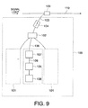
- Fig. 9 shows an embodiment of Raman amplifier 100 in which the semiconductive laser module described in any of the foregoing embodiments is used as a pumping light source module.
- the Raman amplifier 100 is configured as a forward pumping type optical amplifier having a plurality of laser units 101 for outputting different wavelengths of light, a WDM coupler 102 for performing a wavelength combination of output light from the laser units 101, an optical fiber 103 for transmitting the wavelength-combined light, and a polarization dependent type optical isolator 104 disposed in the optical fiber 103.
- Each laser unit 101 has a semiconductive laser module 105 described in any of the foregoing embodiments, an optical fiber 106 for transmitting output light from the semiconductive laser module 105, a depolarizer 107 as a PMF inserted in the optical fiber 106, and a controller 108.
- the semiconductive laser module 105 of each laser unit 101 is adapted to output a laser beam of a particular wavelength different from other laser units 101 in accordance with operational control of the semiconductive laser device by the controller 108, for example, control on an injection current or Peltier module temperature.
- the depolarizer 107 may for example be a PMF provided at least one part of the optical fiber 106, with a proper axis inclined at 45 degrees relative to a polarization plane of the laser beam outputted from the semiconductive laser module 105. By such an arrangement, it is allowed for the laser beam outputted from the semiconductive laser module 105 to be reduced in DOP, not to be polarized.
- the optical isolator 104 passes the laser beam outputted from the semiconductive laser module 105, while cutting return light to the semiconductive laser module 105. It however is unnecessary to use the in-line optical isolator 104 in the case the semiconductive laser module 105 has an incorporated optical isolator.
- laser beams outputted from the semiconductive laser modules 105 are reduced in DOP by the depolarizers 107 in the respective laser units 101, and then combined between different wavelengths of light by the WDM coupler 102, to be transmitted through the optical fiber 103, via the optical isolator 104, to a WDM coupler 109, whereby the transmitted light is input to an optical fiber 110, where signal light is transmitted.
- the signal light being transmitted is Raman amplified by the input laser light (pumping light).
- the Raman amplifier 100 by use of laser units 101 and semiconductive laser modules 105 according to any of the foregoing embodiments, it is allowed to have a high Raman gain, with a suppressed SBS in the optical fiber 110.
- the PMF which is necessary as a depolarizer 107 for DOP reduction, can be short, allowing for the laser units 101 and the Raman amplifier 100 to be small-sized.
- the use of an optical filter reflecting predetermined wavelengths of light allows the Raman gain to be satisfactory in wavelength stability.
- Fig. 10 shows another embodiment of Raman amplifier in which the before-mentioned semiconductive laser module is used as a pumping light source module.
- the Raman amplifier 111 is configured as a forward pumping type optical amplifier having a plurality of laser units 101 for outputting different wavelengths of light, a WDM coupler 102 for performing a wavelength combination of output light from the laser units 101, an optical fiber 103 for transmitting the wavelength-combined light, and a polarization dependent type optical isolator 104 disposed in the optical fiber 103.
- Each laser unit 101 has two semiconductive laser modules 105 described in any of the foregoing embodiments, optical fibers 106 for respectively transmitting laser beams outputted from the semiconductive laser modules 105, a PBC (polarization beam combiner) 112 for performing a polarization combination of the laser beams, an optical fiber 106 for transmitting a polarization-combined beam, and a controller 108 constituting a control means in the present invention.
- a PBC polarization beam combiner
- the plural semiconductive laser modules 105 of each laser unit 101 is adapted to output laser beams with different wavelengths in accordance with operational control of the semiconductive laser device by the controller 108, for example, control on an injection current or Peltier module temperature.
- the optical isolator 104 passes the laser beams outputted from the semiconductive laser modules 105, while cutting return light to the semiconductive laser modules 105. It however is unnecessary to use the in-line optical isolator 104 in the case the semiconductive laser modules 105 have their incorporated optical isolators.
- laser beams outputted from the semiconductive laser modules 105 enter the PBC's 112, where they are combined between polarized light identical in wavelength and different in polarization plane, with reduced degrees of polarization, before resultant light enter the WDM coupler 102, where they are wavelength-combined, to be transmitted through the optical fiber 103, via the optical isolator 104, to a WDM coupler 109, whereby the transmitted light is input to an optical fiber 110, where signal light is transmitted.
- the signal light being transmitted is Raman amplified by the input laser light (pumping light).
- the Raman amplifier 111 by use of laser units 101 and semiconductive laser modules 105 according to any of the foregoing embodiments, it is allowed to have a high Raman gain, with a suppressed SBS in the optical fiber 110.
- the use of an optical filter reflecting predetermined wavelengths of light allows the Raman gain to be satisfactory in wavelength stability.
- Raman amplifiers of the forward pumping system to which the present invention is particularly preferably applicable
- the present invention is not limited to those, and may preferably be applied to the backward pumping system or bi-directional pumping system.
- a pumping light source oriented module a laser unit, and a Raman amplifier using either of them have such effects as follow:
Landscapes
- Physics & Mathematics (AREA)
- General Physics & Mathematics (AREA)
- Optics & Photonics (AREA)
- Condensed Matter Physics & Semiconductors (AREA)
- Electromagnetism (AREA)
- Optical Couplings Of Light Guides (AREA)
- Optical Modulation, Optical Deflection, Nonlinear Optics, Optical Demodulation, Optical Logic Elements (AREA)
- Semiconductor Lasers (AREA)
- Lasers (AREA)
- Mechanical Light Control Or Optical Switches (AREA)
Applications Claiming Priority (2)
| Application Number | Priority Date | Filing Date | Title |
|---|---|---|---|
| JP2000336321A JP2002141609A (ja) | 2000-11-02 | 2000-11-02 | 半導体レーザモジュール、レーザユニット、およびラマン増幅器 |
| JP2000336321 | 2000-11-02 |
Publications (2)
| Publication Number | Publication Date |
|---|---|
| EP1209783A2 true EP1209783A2 (fr) | 2002-05-29 |
| EP1209783A3 EP1209783A3 (fr) | 2004-06-30 |
Family
ID=18811916
Family Applications (1)
| Application Number | Title | Priority Date | Filing Date |
|---|---|---|---|
| EP01309303A Withdrawn EP1209783A3 (fr) | 2000-11-02 | 2001-11-01 | Module laser à semiconducteur et amplificateur raman |
Country Status (5)
| Country | Link |
|---|---|
| US (1) | US20020080833A1 (fr) |
| EP (1) | EP1209783A3 (fr) |
| JP (1) | JP2002141609A (fr) |
| CN (1) | CN1357951A (fr) |
| CA (1) | CA2360965A1 (fr) |
Cited By (3)
| Publication number | Priority date | Publication date | Assignee | Title |
|---|---|---|---|---|
| EP1206018A3 (fr) * | 2000-11-08 | 2002-11-06 | The Furukawa Electric Co., Ltd. | Source de lumière comportant un module de diode laser |
| US6872011B2 (en) | 2001-03-16 | 2005-03-29 | The Furukawa Electric Co., Ltd. | Light source having plural laser diode modules |
| WO2007037936A1 (fr) * | 2005-09-28 | 2007-04-05 | Bookham Technology Plc | Laser a bande etroite presentant une longueur d'onde stable |
Families Citing this family (31)
| Publication number | Priority date | Publication date | Assignee | Title |
|---|---|---|---|---|
| US6924926B2 (en) * | 2001-08-03 | 2005-08-02 | Xtera Communications, Inc. | Laser diode pump sources |
| US6950452B2 (en) * | 2001-09-28 | 2005-09-27 | The Furukawa Electric Co., Ltd. | Semiconductor laser module and method for simultaneously reducing relative intensity noise (RIN) and stimulated brillouin scattering (SBS) |
| JP2003124566A (ja) * | 2001-10-10 | 2003-04-25 | Opnext Japan Inc | 半導体レーザ制御モジュール及び光システム |
| US6920158B2 (en) * | 2001-12-25 | 2005-07-19 | Mitsubishi Denki Kabushiki Kaisha | Optical module |
| US7052733B2 (en) * | 2002-01-10 | 2006-05-30 | Hon Hai Precision Ind. Co., Ltd. | Method for making thin film filter having a negative temperature drift coefficient |
| US7035484B2 (en) * | 2002-04-12 | 2006-04-25 | Xtellus, Inc. | Tunable optical filter |
| SE524828C2 (sv) * | 2002-06-06 | 2004-10-12 | Alfa Exx Ab | Resonator |
| WO2005033626A1 (fr) | 2003-09-30 | 2005-04-14 | Cymer, Inc. | Module d'analyse spectral a laser mopa a decharge gazeuse |
| JP4715171B2 (ja) * | 2004-11-19 | 2011-07-06 | 旭硝子株式会社 | 半導体レーザモジュール及びラマン増幅器 |
| US7580441B2 (en) * | 2005-12-07 | 2009-08-25 | Electronics And Telecommunications Research Institute | Athermal external cavity laser |
| IL174669A (en) * | 2006-03-30 | 2011-10-31 | Eci Telecom Ltd | Method for regulating osnr in a given fiber optic transmission line |
| JP5141270B2 (ja) * | 2008-01-31 | 2013-02-13 | 株式会社島津製作所 | 波長変換レーザ装置 |
| US8594502B2 (en) * | 2009-04-15 | 2013-11-26 | Ofs Fitel, Llc | Method and apparatus using distributed raman amplification and remote pumping in bidirectional optical communication networks |
| US8498507B2 (en) * | 2011-05-13 | 2013-07-30 | Kestrel Labs, Inc. | Anti-reflective launch optics for laser to fiber coupling in a photoplethysmograpic device |
| KR20130093704A (ko) * | 2011-12-23 | 2013-08-23 | 한국전자통신연구원 | 사용자 선택형 레이저 및 이를 포함하는 광 송신기 |
| KR101361175B1 (ko) * | 2012-06-14 | 2014-02-10 | (주)에이앤아이 | 컬리메이터 렌즈 및 집광렌즈를 구비한 색차계모듈 및 이를 이용한 색상계측기 |
| WO2014000311A1 (fr) * | 2012-06-30 | 2014-01-03 | 华为技术有限公司 | Laser à cavité externe |
| TWI485349B (zh) * | 2012-07-18 | 2015-05-21 | Lextar Electronics Corp | 發光裝置 |
| CN103779784B (zh) * | 2014-02-24 | 2016-08-17 | 南京派光信息技术有限公司 | 一种用于拉曼光谱测量的半导体激光器 |
| CN104682188B (zh) * | 2015-03-31 | 2017-10-31 | 吕志伟 | 基于受激布里渊散射的模块化非共线串行组束激光器 |
| CN105005335B (zh) * | 2015-07-06 | 2017-07-28 | 广东石油化工学院 | 一种喇曼光纤放大器的温度控制装置 |
| JP7019283B2 (ja) * | 2016-02-15 | 2022-02-15 | 古河電気工業株式会社 | 波長可変型レーザモジュールおよびその波長制御方法 |
| DE102016107336B4 (de) * | 2016-04-20 | 2017-11-02 | Carl Zeiss Industrielle Messtechnik Gmbh | Koordinatenmessgerät, Verfahren zur Herstellung eines Koordinatenmessgeräts und Verfahren zur Messung eines optischen Filters |
| JP6880566B2 (ja) * | 2016-04-25 | 2021-06-02 | 株式会社リコー | 光源装置、画像形成装置、画像表示装置、物体装置及び色光生成方法 |
| JP7086537B2 (ja) * | 2017-07-27 | 2022-06-20 | 京セラSoc株式会社 | 外部共振器型半導体レーザ装置 |
| JP6981370B2 (ja) * | 2018-06-08 | 2021-12-15 | 日本電信電話株式会社 | 受光装置およびその製造方法 |
| WO2020166670A1 (fr) * | 2019-02-13 | 2020-08-20 | 大学共同利用機関法人自然科学研究機構 | Dispositif de traitement laser et procédé de traitement laser |
| JP7364850B2 (ja) * | 2019-04-16 | 2023-10-19 | 日亜化学工業株式会社 | 外部共振器型半導体レーザ |
| US11499817B2 (en) * | 2020-05-29 | 2022-11-15 | Mitutoyo Corporation | Coordinate measuring machine with vision probe for performing points-from-focus type measurement operations |
| JP7469976B2 (ja) | 2020-07-15 | 2024-04-17 | 横河電機株式会社 | 光源装置及び光パルス試験器 |
| CN119297730A (zh) * | 2024-08-30 | 2025-01-10 | 渚羽科技(杭州)有限公司 | 一种环形窄线宽激光器及控制方法 |
Family Cites Families (10)
| Publication number | Priority date | Publication date | Assignee | Title |
|---|---|---|---|---|
| JPH0621549A (ja) * | 1992-07-01 | 1994-01-28 | Koshin Kogaku:Kk | 波長可変半導体レーザー及び外部共振ユニット |
| JPH06326382A (ja) * | 1993-05-14 | 1994-11-25 | Koshin Kogaku:Kk | 外部共振半導体レーザー |
| JPH1117286A (ja) * | 1997-06-27 | 1999-01-22 | Ando Electric Co Ltd | 波長可変レーザ装置 |
| JPH1140883A (ja) * | 1997-07-22 | 1999-02-12 | Ando Electric Co Ltd | 可変波長半導体レーザ光源 |
| JPH1168233A (ja) * | 1997-08-26 | 1999-03-09 | Ando Electric Co Ltd | 可変波長レーザ光源 |
| JPH11186642A (ja) * | 1997-12-25 | 1999-07-09 | Nec Corp | 光増幅器 |
| JPH11307864A (ja) * | 1998-04-23 | 1999-11-05 | Ando Electric Co Ltd | 外部共振器型波長可変光源 |
| JP2000174381A (ja) * | 1998-12-04 | 2000-06-23 | Nec Corp | 半導体レーザモジュール |
| FR2786937B1 (fr) * | 1998-12-04 | 2001-02-16 | Photonetics | Source multi-longueur d'onde |
| JP2000208869A (ja) * | 1999-01-08 | 2000-07-28 | Sumitomo Electric Ind Ltd | 発光素子モジュ―ル |
-
2000
- 2000-11-02 JP JP2000336321A patent/JP2002141609A/ja active Pending
-
2001
- 2001-11-01 EP EP01309303A patent/EP1209783A3/fr not_active Withdrawn
- 2001-11-01 US US09/985,006 patent/US20020080833A1/en not_active Abandoned
- 2001-11-01 CA CA002360965A patent/CA2360965A1/fr not_active Abandoned
- 2001-11-02 CN CN01134561A patent/CN1357951A/zh active Pending
Cited By (4)
| Publication number | Priority date | Publication date | Assignee | Title |
|---|---|---|---|---|
| EP1206018A3 (fr) * | 2000-11-08 | 2002-11-06 | The Furukawa Electric Co., Ltd. | Source de lumière comportant un module de diode laser |
| US6839367B2 (en) | 2000-11-08 | 2005-01-04 | The Furukawa Electric Co., Ltd. | Light source comprising laser diode module |
| US6872011B2 (en) | 2001-03-16 | 2005-03-29 | The Furukawa Electric Co., Ltd. | Light source having plural laser diode modules |
| WO2007037936A1 (fr) * | 2005-09-28 | 2007-04-05 | Bookham Technology Plc | Laser a bande etroite presentant une longueur d'onde stable |
Also Published As
| Publication number | Publication date |
|---|---|
| JP2002141609A (ja) | 2002-05-17 |
| CN1357951A (zh) | 2002-07-10 |
| CA2360965A1 (fr) | 2002-05-02 |
| US20020080833A1 (en) | 2002-06-27 |
| EP1209783A3 (fr) | 2004-06-30 |
Similar Documents
| Publication | Publication Date | Title |
|---|---|---|
| EP1209783A2 (fr) | Module laser à semiconducteur et amplificateur raman | |
| US6525872B1 (en) | Fiber grating-stabilized, semiconductor pump source | |
| EP0812039B1 (fr) | Source de lumière à fibre optique avec coupleur à fibre multimode | |
| US6950452B2 (en) | Semiconductor laser module and method for simultaneously reducing relative intensity noise (RIN) and stimulated brillouin scattering (SBS) | |
| US6041072A (en) | Apparatus for stabilizing multiple laser sources and their application | |
| US5657153A (en) | Optical amplifier with complementary modulation signal inputs | |
| US6680960B2 (en) | Semiconductor laser device having a diffraction grating on a light emission side | |
| JP2000098433A5 (fr) | ||
| US20020118715A1 (en) | Semiconductor laser module and Raman amplifier using the module | |
| US6947463B2 (en) | Semiconductor laser device for use in a laser module | |
| US6614823B2 (en) | Semiconductor laser device having a diffraction grating on a light reflection side | |
| JPH10215017A (ja) | 光源装置、光増幅器及び光通信システム | |
| JP4629852B2 (ja) | 半導体レーザモジュールとそれを用いた光増幅器 | |
| JP4712178B2 (ja) | 半導体レーザモジュール、レーザユニット、ラマン増幅器、及びラマン増幅器に用いられる光半導体レーザモジュールのブリリュアン散乱抑制および偏光度低減方法 | |
| JP2003283036A (ja) | 半導体レーザモジュールおよびこれを用いたラマン増幅器 | |
| JP3273911B2 (ja) | 光ファイバ増幅器、励起用半導体レーザモジュールおよび光信号伝送システム | |
| JP4234353B2 (ja) | 半導体レーザモジュールおよびこれを用いた光ファイバ増幅器 | |
| EP1255335A2 (fr) | Dispositif laser à semicoducteur ayant un réseau de diffraction sur un côté réfléchissant | |
| JP3752171B2 (ja) | 半導体レーザ装置、半導体レーザモジュールおよびこれを用いたラマン増幅器 | |
| KR100234202B1 (ko) | 광섬유증폭을 위한 고전력 펌핑장치 | |
| Yoshida et al. | Novel concepts in 14XX-nm pump lasers for Raman amplifiers | |
| EP1255336A2 (fr) | Dispositif laser à semicoducteur ayant un réseau de diffraction sur un côté réfléchissant | |
| JP2003347652A (ja) | 半導体レーザモジュールおよびこれを用いた光ファイバ増幅器 | |
| JP2004014537A (ja) | 半導体レーザ装置、半導体レーザモジュールおよびこれを用いた光ファイバ増幅器 | |
| JP2004119653A (ja) | 広帯域ase光源 |
Legal Events
| Date | Code | Title | Description |
|---|---|---|---|
| PUAI | Public reference made under article 153(3) epc to a published international application that has entered the european phase |
Free format text: ORIGINAL CODE: 0009012 |
|
| AK | Designated contracting states |
Kind code of ref document: A2 Designated state(s): AT BE CH CY DE DK ES FI FR GB GR IE IT LI LU MC NL PT SE TR |
|
| AX | Request for extension of the european patent |
Free format text: AL;LT;LV;MK;RO;SI |
|
| RIC1 | Information provided on ipc code assigned before grant |
Ipc: 7H 01S 3/30 B Ipc: 7H 01S 5/14 A |
|
| PUAL | Search report despatched |
Free format text: ORIGINAL CODE: 0009013 |
|
| AK | Designated contracting states |
Kind code of ref document: A3 Designated state(s): AT BE CH CY DE DK ES FI FR GB GR IE IT LI LU MC NL PT SE TR |
|
| AX | Request for extension of the european patent |
Extension state: AL LT LV MK RO SI |
|
| AKX | Designation fees paid | ||
| REG | Reference to a national code |
Ref country code: DE Ref legal event code: 8566 |
|
| STAA | Information on the status of an ep patent application or granted ep patent |
Free format text: STATUS: THE APPLICATION IS DEEMED TO BE WITHDRAWN |
|
| 18D | Application deemed to be withdrawn |
Effective date: 20041231 |