EP1209902A1 - Méthode et système de prise d'images - Google Patents
Méthode et système de prise d'images Download PDFInfo
- Publication number
- EP1209902A1 EP1209902A1 EP01124359A EP01124359A EP1209902A1 EP 1209902 A1 EP1209902 A1 EP 1209902A1 EP 01124359 A EP01124359 A EP 01124359A EP 01124359 A EP01124359 A EP 01124359A EP 1209902 A1 EP1209902 A1 EP 1209902A1
- Authority
- EP
- European Patent Office
- Prior art keywords
- moving
- pedestal
- angle
- camera
- image
- Prior art date
- Legal status (The legal status is an assumption and is not a legal conclusion. Google has not performed a legal analysis and makes no representation as to the accuracy of the status listed.)
- Granted
Links
- 238000000034 method Methods 0.000 title claims abstract description 34
- NJPPVKZQTLUDBO-UHFFFAOYSA-N novaluron Chemical compound C1=C(Cl)C(OC(F)(F)C(OC(F)(F)F)F)=CC=C1NC(=O)NC(=O)C1=C(F)C=CC=C1F NJPPVKZQTLUDBO-UHFFFAOYSA-N 0.000 claims abstract description 118
- 238000001514 detection method Methods 0.000 claims description 10
- 230000003287 optical effect Effects 0.000 description 17
- 238000010586 diagram Methods 0.000 description 8
- 230000000670 limiting effect Effects 0.000 description 2
- 239000003550 marker Substances 0.000 description 2
- 238000005259 measurement Methods 0.000 description 2
- BZHJMEDXRYGGRV-UHFFFAOYSA-N Vinyl chloride Chemical compound ClC=C BZHJMEDXRYGGRV-UHFFFAOYSA-N 0.000 description 1
- 230000015572 biosynthetic process Effects 0.000 description 1
- 239000003086 colorant Substances 0.000 description 1
- 238000007796 conventional method Methods 0.000 description 1
- 230000003247 decreasing effect Effects 0.000 description 1
- 230000000694 effects Effects 0.000 description 1
- 238000005286 illumination Methods 0.000 description 1
- 238000004091 panning Methods 0.000 description 1
- 238000003786 synthesis reaction Methods 0.000 description 1
Images


Classifications
-
- H—ELECTRICITY
- H04—ELECTRIC COMMUNICATION TECHNIQUE
- H04N—PICTORIAL COMMUNICATION, e.g. TELEVISION
- H04N5/00—Details of television systems
- H04N5/222—Studio circuitry; Studio devices; Studio equipment
- H04N5/2224—Studio circuitry; Studio devices; Studio equipment related to virtual studio applications
-
- H—ELECTRICITY
- H04—ELECTRIC COMMUNICATION TECHNIQUE
- H04N—PICTORIAL COMMUNICATION, e.g. TELEVISION
- H04N23/00—Cameras or camera modules comprising electronic image sensors; Control thereof
- H04N23/60—Control of cameras or camera modules
-
- H—ELECTRICITY
- H04—ELECTRIC COMMUNICATION TECHNIQUE
- H04N—PICTORIAL COMMUNICATION, e.g. TELEVISION
- H04N5/00—Details of television systems
- H04N5/222—Studio circuitry; Studio devices; Studio equipment
Definitions
- the present invention relates to an image pick-up method and an image pick-up system of a mobile-type camera system used for location of movies and television programs, and more specifically to an image pick-up method and an image pick-up system of a mobile-type camera system suitable for shooting in virtual studios.
- a mobile-type camera system When shooting in a studio, a mobile-type camera system is used and it has a structure in which a pan head is set on a mobile base called pedestal, and a camera is placed on the pan head. Then, a cameraman shoots a scene while moving the pedestal so as to change the camera angle appropriately.
- a real object image taken with the camera system in the studio and computer graphics (CG) created as its background or effect are operated together in relation with each other while maintaining the three-dimensional relationship in position as viewed from the camera position.
- CG computer graphics
- techniques of analyzing the two-dimensional position of the pedestal in the virtual space, as well as the position and angle of the camera set on the pedestal are employed. That is, according to these techniques, when the two-dimensional position of the pedestal and the position and angle of the camera are determined, the relationship among the positions of the pedestal, camera, an object and CG can be found out by calculation. In this manner, the object taken by the camera and the CG image can be combined and moved together in relation with each other while maintaining the three-dimensional relationship between the positions of the object and the CG image.
- position marks cannot be read from the position of the pedestal. More specifically, there are, usually, a great number of lighting tools which are suspended from the ceiling of a studio, and some of them physically block the view. Further, the reading of a position mark may be disturbed by illumination light.
- a mark included in the background image must be always located within the view of the camera, and therefore the movable range of the camera is limited. Further, when the size of the object increases in the image, such as in zoom-in for close-ups, etc., the ratio of the mark included in the background image may be excessively decreased as compared to the whole scene, thus making it impossible to detect it in the image.
- the movement of the camera is limited by the tracks of the rails, and therefore the applicability is low.
- the object of the present invention is to provide an image pick-up method and an image pick-up system which can find the relationship in position between the camera and an object at a high accuracy, inexpensively and without causing limitation to shooting.
- an image pick-up method for picking up an image of an object with a camera mounted via a pan head on a moving pedestal comprising the steps of: setting a reference position on a floor surface on which the moving pedestal moves, and a reference angle of the moving pedestal; detecting a moving amount of the moving pedestal from said reference position and a rotation angle thereof from said reference angle; finding a position and an angle of the camera with respect to the object on the basis of said reference position, said reference angle, said moving amount and said rotation angle of the moving pedestal; and transmitting data of the position and the angle of the camera with respect to the object, to a computer for creating an image containing a real object image of the object taken with the camera.
- an image pick-up system for picking up an image of an object, comprising: a camera unit having a structure in which a camera for picking up an image of an object, is mounted via a pan head on a moving pedestal; an operation means for calculating a positional relationship between the camera and the object; a setting means for setting a reference position on a floor surface on which the moving pedestal moves, and a reference angle of the moving pedestal to said operation means; and a detection means for detecting a moving amount of the moving pedestal from the reference 'position, and a rotation angle thereof from the reference angle, wherein said operation means calculates out a position and an angle of the camera with respect to the object on the basis of the reference position, the reference angle, the moving amount and the rotation angle of the moving pedestal, and transmits data of the position and the angle of the camera with respect to the object, to a computer for creating an image containing a real object image of the object taken with the camera.
- an image pick-up system for picking up an image of an object, comprising: a moving pedestal including three wheels; a camera unit having a structure in which a camera for picking up an image of an object, is mounted via a pan head on said moving pedestal; an operation means for calculating a positional relationship between the camera and the object; three encoders provided respectively for the three wheels of said moving pedestal; a plurality of sensors provided on said moving pedestal, for detecting a predetermined mark made on a floor surface on which said moving pedestal moves; and a setting means for setting a reference position on the floor surface, and a reference angle of said moving pedestal, which are found from detection values of said plurality of sensors and a pulse numbers counted by said encoders in the movement of said moving pedestal, to said operation means, wherein said operation means calculates out a position and an angle of the camera with respect to the object on the basis of the reference position, the reference angle, the moving amount and the rotation angle of said moving pedestal, which are obtained from the pulse numbers
- the reference position is set on the floor surface on which the moving pedestal is moved around, and the moving amount of the pedestal from the reference position and the rotation angle from the reference angle are detected.
- the reference angle, the moving amount of the moving pedestal and the rotation angle thereof, the position and angle of the camera with respect to the object can be found.
- the positional relationship between the camera and the object can be found without especially providing costly facilities or without limiting the shooting operation.
- the moving. pedestal can be moved around at random, and therefore present invention has a high applicability.
- an error created due to the change in the tire diameter of the moving pedestal, or the change in the angle of the moving pedestal can be suppressed to a very low level, and therefore the position and the angle of the moving pedestal can be accurately found.
- an image containing the real object image shot with the camera can be created at a high accuracy.
- the moving amount of the moving pedestal it is desirable to obtain the moving amount of the moving pedestal by measuring a length of a portion of the wheel of the moving pedestal, which has been brought into contact with the floor surface. As a result, the moving distance of the moving pedestal can be accurately found.
- the rotation angle of the moving pedestal can be calculated from the moving distances of two of at least three wheels of the pedestal, which are distant with respect to the moving direction. In this manner, the angle of the moving pedestal can be accurately found. Further, the two wheels can be selected which are most distant. In this manner, the angle of the moving pedestal can be more accurately found.
- the first and second lines are formed on the floor surface so that they normally cross with each other from the reference position, and two of the first sensors for detecting the first line and one second sensor for detecting the second line are provided on the moving pedestal, and the reference position and the reference angle can be found on the basis of the moving amount at a time when the two first sensors each pass the first line, and the moving amount at a time when the second sensor passes the second line. In this manner, the reference position and reference angle of the moving pedestal can be easily found.
- FIG. 1 is a side view of a TV camera unit used in the image pick-up method according to the present invention
- FIG. 2 is a plan view thereof.
- a TV camera unit 1 includes a pedestal 2 serving as a moving base which runs on the floor surface of a studio, a pan head 3 set thereon, and a TV camera 4 mounted on the pan head 3, and the TV camera 4 can be rotated and tilted by means of the pan head 3. Also shown are a handle 5 used for changing the moving direction of the pedestal, and a lever 6 used for tilting or rotating the TV camera 4.
- the pedestal 2 has a bottom portion provided with three running wheels 7a, 7b and 7c. Further, the bottom portion of the pedestal 2 has two of first optical sensors 8a and 8b, and one second optical sensor 9, which are used to set or correct the reference position and reference angle of the pedestal 2.
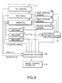
- encoders 11a, 11b and 11c for detecting the running distance (movement amount) are connected to the rotation shafts of the wheels 7a, 7b and 7c of the pedestal 2. These encoders 11a, 11b, 11c, the first optical sensors 8a and 8b and the second optical sensor 9 are connected to a reference setting section 12. On the basis of data sent from the encoders 11a, 11b, 11c, the first optical sensors 8a and 8b and the second optical sensor 9, the reference position on the floor surface on which the pedestal 2 travels as well as the reference angle of the pedestal 2 are obtained by the reference setting section 12 as will be described later, and these data are set to an arithmetic operation section 13 (STEP 1 in FIG. 4). Further, other data such the steering angle of the pedestal 2, the panning and tilting of the pan head 3, the zooming and focusing of the TV camera 4 are also inputted to the arithmetic operation section 13.
- the running distance (movement amount) of the wheels 7a, 7b and 7c are detected by the encoders 11a, 11b and 11c, and then, based on these detected values, the movement amount of the pedestal 2 from the reference position and the rotation angle from the reference angle are calculated by the operation section 13 (STEP 2 in FIG. 4).
- the operation section 13 From the data of the reference position and reference angle sent from the reference setting section 12, the movement amount of the pedestal 2 and the data of the rotation angle obtained from the reference angle, the position and angle of the TV camera 4 with respect to the object are calculated by the operation section 13 (STEP 3 in FIG. 4).
- the data of the position and angle of the TV camera 4 with respect to the object, which are calculated by the operation section 13, are sent to an image forming computer 14 (STEP 4 in FIG. 4).
- the image forming computer 14 is able to operate a real object image (shot point 20) taken with the TV camera 4 and a virtual image projected on a virtual screen 30 in background of the real object, in relation with each other.
- the moving amount of the pedestal 2 is measured with use of the encoders 11a, 11b and 11c mounted on the rotation shafts of the wheels 7a, 7b and 7c, respectively, as described above.
- the measurement of the moving amount with use of encodes is carried out in the following manner. That is, generally, the moving amount is calculated by dividing the diameter of the wheel with the number of pulse per one rotation detected by the encoder.
- the wheels (usually three of them) of the cart of the pedestal 2 are usually made of rubber, and therefore the contact state between the wheels and the floor surface varies from a case of running straight to a case of making a turn, thereby changing the diameter of the tire at the contact portion. Therefore, if the moving amount is measured directly from the rotation of the shaft and the diameter of the wheels, an error results and the measurement is not accurate.
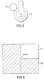
- this embodiment provides a roller 15 whose diameter is known to each wheel (wheel 7a in FIG.6).
- the roller 15 rotates along with the rotation of the wheel, and therefore when the rotation number of the roller 15 is known, the length of a portion of the wheel, which is brought into contact with the floor, can be accurately detected regardless of the state of the wheel. More specifically, when the diameter of the roller 15 is divided by the pulse number per one rotation, the moving amount of the roller 15 is calculated.
- the moving amount of the wheel can be accurately obtained from this calculated value of the roller.
- an X-axis and a Y-axis are formed with an origin corresponding to the reference position on the floor, and the pedestal 2 is moved around. Then, the difference in count between the encoders 11a and 11b of the wheels 7a and 7b at an instantaneous moment when the first optical sensors 8a and 8b pass the X-axis, which is the Y origin, is calculated. Based on thus calculated difference, the angle of the pedestal 2 is corrected, and the Y origin is calculated. Subsequently, on the basis of the position at an instantaneous moment when the second optical sensor 9 passes the X origin, the position of the X origin is calculated out from the current angle correction value. It should be noted that in this figure, the first optical sensors 8a and 8b, and the second optical sensor 9 are indicated in the form of arrows directed towards the line to be detected.
- FIG. 7B illustrates the just-mentioned status.
- the pedestal 2 is moved further only a small distance, so as to obtain new values a and b. From the newly obtained values and b, a new ⁇ for the small distance is obtained. If thus newly obtained ⁇ value is added to the previously obtained ⁇ value, the rotation angle for the small distance moved can be known. Therefore, from the newly obtained values of a, b and ⁇ , the position of the pedestal when it is moved by a small distance, can be known. Then, by repeating the above-described operation, the position and rotation angle of the pedestal 2 can be detected at all times.
- a reference position passing point should be formed by combining two kinds of plate members 21 and 22 of different colors (for example, of hard vinyl chloride plate) together as shown in FIG. 8. In this manner, the horizontality and verticality can be guaranteed by the accuracy of the cut surface of the plate members, and therefore the reference position can be set at a high accuracy.
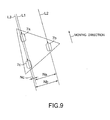
- This embodiment is characterized by how to select which two of the three wheels should be selected for the calculation, and a pair of wheels most distant in terms of the moving direction should be selected. More specifically, as shown in FIG. 9, let us draw lines L1, L2 and L3 which pass the center of the three wheels 7a, 7b and 7c, and are parallel to the moving direction. Then, the distance Na between L1 and L2, the distance Nb between L2 and L3, and the distance Nc between L3 and L1 are measured, and such a pair of wheels that have the longest distance should be selected. In the case shown in FIG. 9, the distance Nb is the longest and therefore the wheels 7b and 7c are selected. With this selection, the rotation angle can be calculated at a high accuracy.
- the moving direction is determined by the steering angle of the ring-shaped handle 5 mounted on the pedestal 2, and therefore subject wheels for the calculation may be automatically selected on the basis of the steering angle of the handle 5 by presetting, or the optical wheels may be selected by the computer mounted on the pedestal 2.
Landscapes
- Engineering & Computer Science (AREA)
- Multimedia (AREA)
- Signal Processing (AREA)
- Length Measuring Devices By Optical Means (AREA)
Applications Claiming Priority (2)
| Application Number | Priority Date | Filing Date | Title |
|---|---|---|---|
| JP2000325785 | 2000-10-25 | ||
| JP2000325785 | 2000-10-25 |
Publications (2)
| Publication Number | Publication Date |
|---|---|
| EP1209902A1 true EP1209902A1 (fr) | 2002-05-29 |
| EP1209902B1 EP1209902B1 (fr) | 2011-11-23 |
Family
ID=18803089
Family Applications (1)
| Application Number | Title | Priority Date | Filing Date |
|---|---|---|---|
| EP01124359A Expired - Lifetime EP1209902B1 (fr) | 2000-10-25 | 2001-10-23 | Méthode et système de prise d'images |
Country Status (3)
| Country | Link |
|---|---|
| US (1) | US7161620B2 (fr) |
| EP (1) | EP1209902B1 (fr) |
| ES (1) | ES2377193T3 (fr) |
Cited By (3)
| Publication number | Priority date | Publication date | Assignee | Title |
|---|---|---|---|---|
| GB2471267A (en) * | 2009-06-16 | 2010-12-29 | Vitec Group Plc | Pedestal navigation system |
| WO2011076221A2 (fr) | 2009-12-23 | 2011-06-30 | 360 Development Aps | Procédé de fourniture d'une série d'images numériques |
| EP3104330A1 (fr) | 2015-06-09 | 2016-12-14 | Fraunhofer-Gesellschaft zur Förderung der angewandten Forschung e.V. | Procede de suivi d'au moins un objet et procede de remplacement d'au moins un objet par un objet virtuel dans un signal d'image animee enregistre par une camera |
Families Citing this family (4)
| Publication number | Priority date | Publication date | Assignee | Title |
|---|---|---|---|---|
| US7408654B1 (en) * | 2004-09-02 | 2008-08-05 | Mark Randall Hardin | Method for measuring position, linear velocity and velocity change of an object in two-dimensional motion |
| DE102005058867B4 (de) * | 2005-12-09 | 2018-09-27 | Cine-Tv Broadcast Systems Gmbh | Verfahren und Vorrichtung zum Bewegen einer auf einem Schwenk- und Neigekopf angeordneten Kamera entlang einer vorgegebenen Bewegungsbahn |
| TWI421971B (zh) * | 2011-05-13 | 2014-01-01 | Univ Nat Taipei Technology | 物件定位方法 |
| PL422770A1 (pl) * | 2017-09-06 | 2019-03-11 | Kobiałka Bartłomiej | Urządzenie i sposób do wykonywania zdjęć obiektów |
Citations (5)
| Publication number | Priority date | Publication date | Assignee | Title |
|---|---|---|---|---|
| US3741473A (en) | 1971-12-08 | 1973-06-26 | C Finley | Odometer |
| US5008804A (en) | 1988-06-23 | 1991-04-16 | Total Spectrum Manufacturing Inc. | Robotic television-camera dolly system |
| EP0458722A1 (fr) | 1990-05-22 | 1991-11-27 | Investronica S.A. | Assemblage pour la manipulation et le transport sous commande programmée de boîtes, récipients ou similaire |
| US5930740A (en) * | 1997-04-04 | 1999-07-27 | Evans & Sutherland Computer Corporation | Camera/lens calibration apparatus and method |
| EP0971319A2 (fr) | 1991-04-26 | 2000-01-12 | Discreet Logic Inc. | Procédé de modélisation d un système de prise de vues et procédé et système de réalisation de combinaisons d images réelles et d images de synthèse |
Family Cites Families (9)
| Publication number | Priority date | Publication date | Assignee | Title |
|---|---|---|---|---|
| US4092673A (en) * | 1976-05-18 | 1978-05-30 | Adams Jay W | Compatible composite image process |
| WO1992002871A1 (fr) * | 1990-08-08 | 1992-02-20 | Digital Arts Film & Television Pty. Ltd. | Systeme de commande de mouvement pour la technique cinematographique |
| GB2259823A (en) | 1991-09-17 | 1993-03-24 | Radamec Epo Limited | Navigation system |
| US5471385A (en) * | 1992-05-21 | 1995-11-28 | Tsubakimoto Chain Co. | Routeless guiding method for moving body |
| GB2278907A (en) * | 1993-06-08 | 1994-12-14 | Vinten Group Plc | Manual control system for camera mountings |
| DE59506365D1 (de) * | 1994-01-28 | 1999-08-12 | Cfb Gmbh | Vorrichtung und verfahren zur herstellung einer bildsequenz |
| GB9607541D0 (en) * | 1996-04-11 | 1996-06-12 | Discreet Logic Inc | Processing image data |
| US6264330B1 (en) * | 1996-12-30 | 2001-07-24 | Sony Corporation | Self-propelled camera dolly |
| GB9702636D0 (en) * | 1997-02-01 | 1997-04-02 | Orad Hi Tech Systems Limited | Virtual studio position sensing system |
-
2001
- 2001-10-23 US US10/007,175 patent/US7161620B2/en not_active Expired - Lifetime
- 2001-10-23 EP EP01124359A patent/EP1209902B1/fr not_active Expired - Lifetime
- 2001-10-23 ES ES01124359T patent/ES2377193T3/es not_active Expired - Lifetime
Patent Citations (6)
| Publication number | Priority date | Publication date | Assignee | Title |
|---|---|---|---|---|
| US3741473A (en) | 1971-12-08 | 1973-06-26 | C Finley | Odometer |
| US5008804A (en) | 1988-06-23 | 1991-04-16 | Total Spectrum Manufacturing Inc. | Robotic television-camera dolly system |
| US5008804B1 (fr) | 1988-06-23 | 1993-05-04 | Total Spectrum Manufacturing I | |
| EP0458722A1 (fr) | 1990-05-22 | 1991-11-27 | Investronica S.A. | Assemblage pour la manipulation et le transport sous commande programmée de boîtes, récipients ou similaire |
| EP0971319A2 (fr) | 1991-04-26 | 2000-01-12 | Discreet Logic Inc. | Procédé de modélisation d un système de prise de vues et procédé et système de réalisation de combinaisons d images réelles et d images de synthèse |
| US5930740A (en) * | 1997-04-04 | 1999-07-27 | Evans & Sutherland Computer Corporation | Camera/lens calibration apparatus and method |
Cited By (5)
| Publication number | Priority date | Publication date | Assignee | Title |
|---|---|---|---|---|
| GB2471267A (en) * | 2009-06-16 | 2010-12-29 | Vitec Group Plc | Pedestal navigation system |
| GB2471267B (en) * | 2009-06-16 | 2016-03-09 | Vitec Group Plc | Pedestal navigation system |
| WO2011076221A2 (fr) | 2009-12-23 | 2011-06-30 | 360 Development Aps | Procédé de fourniture d'une série d'images numériques |
| EP3104330A1 (fr) | 2015-06-09 | 2016-12-14 | Fraunhofer-Gesellschaft zur Förderung der angewandten Forschung e.V. | Procede de suivi d'au moins un objet et procede de remplacement d'au moins un objet par un objet virtuel dans un signal d'image animee enregistre par une camera |
| US10110822B2 (en) | 2015-06-09 | 2018-10-23 | Fraunhofer-Gesellschaft zur Förderung der angewandten Forschung e.V. | Method for tracking at least one object and method for replacing at least one object by a virtual object in a moving image signal recorded by a camera |
Also Published As
| Publication number | Publication date |
|---|---|
| US20020164164A1 (en) | 2002-11-07 |
| EP1209902B1 (fr) | 2011-11-23 |
| ES2377193T3 (es) | 2012-03-23 |
| US7161620B2 (en) | 2007-01-09 |
Similar Documents
| Publication | Publication Date | Title |
|---|---|---|
| US10580153B2 (en) | Optical navigation and positioning system | |
| JP4003623B2 (ja) | 旋回可能な監視カメラを用いた画像処理システム | |
| US8897482B2 (en) | Stereo photogrammetry from a single station using a surveying instrument with an eccentric camera | |
| US6556722B1 (en) | Position determination | |
| US8625086B2 (en) | Determining coordinates of a target in relation to a survey instrument having a camera | |
| EP3170367B1 (fr) | Système de visée d'éclairage de stade et procédé | |
| JP4971344B2 (ja) | 測量方法及び測量装置 | |
| JP5650942B2 (ja) | 点検システムおよび点検方法 | |
| WO2009100774A1 (fr) | Localisation d’un instrument de relevé géodésique par rapport à un repère au sol | |
| CN104204848B (zh) | 具有测距相机的勘测设备 | |
| CN111818270B (zh) | 用于多机位摄像的自动控制方法和系统 | |
| EP1209902A1 (fr) | Méthode et système de prise d'images | |
| EP1469281B1 (fr) | Appareil électronique d'arpentage. | |
| JP3926601B2 (ja) | 撮像方法および撮像システム | |
| JP2000121354A (ja) | 距離計測方法 | |
| JP2003042760A (ja) | 計測装置、計測方法及び計測システム | |
| JPH07139942A (ja) | 測量装置 | |
| EP2240741A1 (fr) | Localisation d un instrument de relevé géodésique par rapport à un repère au sol | |
| US20080252746A1 (en) | Method and apparatus for a hybrid wide area tracking system | |
| EP1455253A2 (fr) | Système de positionnement absolu | |
| CN112105487B (zh) | 用于具有位置定位系统的机器人的展演竞赛场 | |
| JP4812099B2 (ja) | カメラ位置検出方法 | |
| JP6954830B2 (ja) | ターゲット装置、測量方法、測量装置および測量用プログラム | |
| JP2001141457A (ja) | 3次元計測装置 | |
| CN105823470A (zh) | 三维位置计测系统 |
Legal Events
| Date | Code | Title | Description |
|---|---|---|---|
| PUAI | Public reference made under article 153(3) epc to a published international application that has entered the european phase |
Free format text: ORIGINAL CODE: 0009012 |
|
| 17P | Request for examination filed |
Effective date: 20011106 |
|
| AK | Designated contracting states |
Kind code of ref document: A1 Designated state(s): AT BE CH CY DE DK ES FI FR GB GR IE IT LI LU MC NL PT SE TR |
|
| AX | Request for extension of the european patent |
Free format text: AL;LT;LV;MK;RO;SI |
|
| RAP1 | Party data changed (applicant data changed or rights of an application transferred) |
Owner name: SHOTOKU LTD. Owner name: TOKYO BROADCASTING SYSTEM INC. |
|
| RAP1 | Party data changed (applicant data changed or rights of an application transferred) |
Owner name: SHOTOKU LTD. Owner name: TOKYO BROADCASTING SYSTEM INC. |
|
| AKX | Designation fees paid |
Designated state(s): DE ES GB |
|
| 17Q | First examination report despatched |
Effective date: 20081112 |
|
| GRAP | Despatch of communication of intention to grant a patent |
Free format text: ORIGINAL CODE: EPIDOSNIGR1 |
|
| RAP1 | Party data changed (applicant data changed or rights of an application transferred) |
Owner name: SHOTOKU LTD. |
|
| GRAA | (expected) grant |
Free format text: ORIGINAL CODE: 0009210 |
|
| GRAS | Grant fee paid |
Free format text: ORIGINAL CODE: EPIDOSNIGR3 |
|
| AK | Designated contracting states |
Kind code of ref document: B1 Designated state(s): DE ES GB |
|
| REG | Reference to a national code |
Ref country code: GB Ref legal event code: FG4D |
|
| REG | Reference to a national code |
Ref country code: DE Ref legal event code: R096 Ref document number: 60145695 Country of ref document: DE Effective date: 20120126 |
|
| REG | Reference to a national code |
Ref country code: ES Ref legal event code: FG2A Ref document number: 2377193 Country of ref document: ES Kind code of ref document: T3 Effective date: 20120323 |
|
| PLBE | No opposition filed within time limit |
Free format text: ORIGINAL CODE: 0009261 |
|
| STAA | Information on the status of an ep patent application or granted ep patent |
Free format text: STATUS: NO OPPOSITION FILED WITHIN TIME LIMIT |
|
| 26N | No opposition filed |
Effective date: 20120824 |
|
| REG | Reference to a national code |
Ref country code: DE Ref legal event code: R097 Ref document number: 60145695 Country of ref document: DE Effective date: 20120824 |
|
| PGFP | Annual fee paid to national office [announced via postgrant information from national office to epo] |
Ref country code: ES Payment date: 20171124 Year of fee payment: 17 |
|
| REG | Reference to a national code |
Ref country code: ES Ref legal event code: FD2A Effective date: 20191202 |
|
| PG25 | Lapsed in a contracting state [announced via postgrant information from national office to epo] |
Ref country code: ES Free format text: LAPSE BECAUSE OF NON-PAYMENT OF DUE FEES Effective date: 20181024 |
|
| PGFP | Annual fee paid to national office [announced via postgrant information from national office to epo] |
Ref country code: DE Payment date: 20201028 Year of fee payment: 20 Ref country code: GB Payment date: 20201026 Year of fee payment: 20 |
|
| REG | Reference to a national code |
Ref country code: DE Ref legal event code: R071 Ref document number: 60145695 Country of ref document: DE |
|
| REG | Reference to a national code |
Ref country code: GB Ref legal event code: PE20 Expiry date: 20211022 |
|
| PG25 | Lapsed in a contracting state [announced via postgrant information from national office to epo] |
Ref country code: GB Free format text: LAPSE BECAUSE OF EXPIRATION OF PROTECTION Effective date: 20211022 |