EP1209948A2 - Gehäuse für akustischen Empfänger für Hörhilfegeräte - Google Patents
Gehäuse für akustischen Empfänger für Hörhilfegeräte Download PDFInfo
- Publication number
- EP1209948A2 EP1209948A2 EP01204474A EP01204474A EP1209948A2 EP 1209948 A2 EP1209948 A2 EP 1209948A2 EP 01204474 A EP01204474 A EP 01204474A EP 01204474 A EP01204474 A EP 01204474A EP 1209948 A2 EP1209948 A2 EP 1209948A2
- Authority
- EP
- European Patent Office
- Prior art keywords
- jacket
- acoustic receiver
- housing
- acoustic
- receiver
- Prior art date
- Legal status (The legal status is an assumption and is not a legal conclusion. Google has not performed a legal analysis and makes no representation as to the accuracy of the status listed.)
- Granted
Links
Images




Classifications
-
- H—ELECTRICITY
- H04—ELECTRIC COMMUNICATION TECHNIQUE
- H04R—LOUDSPEAKERS, MICROPHONES, GRAMOPHONE PICK-UPS OR LIKE ACOUSTIC ELECTROMECHANICAL TRANSDUCERS; ELECTRIC HEARING AIDS; PUBLIC ADDRESS SYSTEMS
- H04R25/00—Electric hearing aids
- H04R25/65—Housing parts, e.g. shells, tips or moulds, or their manufacture
-
- H—ELECTRICITY
- H04—ELECTRIC COMMUNICATION TECHNIQUE
- H04R—LOUDSPEAKERS, MICROPHONES, GRAMOPHONE PICK-UPS OR LIKE ACOUSTIC ELECTROMECHANICAL TRANSDUCERS; ELECTRIC HEARING AIDS; PUBLIC ADDRESS SYSTEMS
- H04R2209/00—Details of transducers of the moving-coil, moving-strip, or moving-wire type covered by H04R9/00 but not provided for in any of its subgroups
- H04R2209/027—Electrical or mechanical reduction of yoke vibration
-
- H—ELECTRICITY
- H04—ELECTRIC COMMUNICATION TECHNIQUE
- H04R—LOUDSPEAKERS, MICROPHONES, GRAMOPHONE PICK-UPS OR LIKE ACOUSTIC ELECTROMECHANICAL TRANSDUCERS; ELECTRIC HEARING AIDS; PUBLIC ADDRESS SYSTEMS
- H04R2225/00—Details of deaf aids covered by H04R25/00, not provided for in any of its subgroups
- H04R2225/49—Reducing the effects of electromagnetic noise on the functioning of hearing aids, by, e.g. shielding, signal processing adaptation, selective (de)activation of electronic parts in hearing aid
-
- H—ELECTRICITY
- H04—ELECTRIC COMMUNICATION TECHNIQUE
- H04R—LOUDSPEAKERS, MICROPHONES, GRAMOPHONE PICK-UPS OR LIKE ACOUSTIC ELECTROMECHANICAL TRANSDUCERS; ELECTRIC HEARING AIDS; PUBLIC ADDRESS SYSTEMS
- H04R25/00—Electric hearing aids
- H04R25/60—Mounting or interconnection of hearing aid parts, e.g. inside tips, housings or to ossicles
- H04R25/604—Mounting or interconnection of hearing aid parts, e.g. inside tips, housings or to ossicles of acoustic or vibrational transducers
Definitions
- the invention relates to receivers used in telecommunications equipment and hearing aids.
- the present invention relates to a housing having improved sturdiness and electromagnetic shielding while still maintaining small dimensions.
- a conventional hearing aid or listening device can include both a microphone and a telecoil for receiving inputs.
- the microphone picks up acoustic sound waves and converts the acoustic sound waves to an audio signal. That signal is then processed (e.g., amplified) and sent to the receiver (or "speaker") of the hearing aid or listening device.
- the speaker then converts the processed signal to an acoustic signal that is broadcast toward the eardrum.
- the telecoil picks up electromagnetic signals.
- the telecoil produces a voltage over its terminals when placed within an electromagnetic field, which is created by an alternating current of an audio signal moving through a wire.
- an equivalent audio signal is induced in the telecoil.
- the signal in the telecoil is then processed (e.g. amplified) and sent to the receiver (or "speaker") of the hearing aid for conversion to an acoustic signal.
- a typical telecommunication system consists of a combination of a receiver and a microphone in one housing.
- the signal from the microphone to the receiver is amplified before the receiver broadcasts the acoustic signal toward the eardrum.
- the housing is made of a soft magnetic material, such as a nickel-iron alloy.
- the housing serves several functions. First, the housing provides some level of sturdiness. Second, the housing also provides a structure for supporting the electrical connections. Third, the housing provides both magnetic and electrical shielding. Lastly, the housing may provide acoustical and vibrational isolation to the rest of the hearing aid.
- the gain introduced between the microphone and the receiver may result in feedback problems.
- the vibration or acoustical radiation of the receiver creates an undesirable feedback signal that is received by the microphone.
- a magnetic feedback signal may create feedback problems.
- the receiver In both hearing aids and telecommunication devices, it is important for the receiver to be configured to withstand the forces associated with handling without damaging the housing. These forces can arise through the assembly of the receiver within a hearing aid, such as when a receiver is grasped with tweezers while it is being positioned or when force is placed on the housing when electrical connections are being made. Disfiguring the housing can easily occur because the housing material is thin and has a low hardness. One common type of damage is a simple dent that can occur in the housing. Dents can affect not only the electronics within the housing, but they can affect the performance of the acoustical chambers within the receiver.
- the housing of a receiver is typically made of a case and a cover that are made by a drawing technique, dents near the interface of the case and cover can also lead to acoustic leaks at the interface. Because of the minimal thickness of the material in the housing and a minimal size of the receiver, magnetic and acoustical isolation are limited.
- An acoustic receiver comprises means for converting an input audio signal into an acoustic signal.
- the receiver has a housing having a plurality of sides that surround the converting means.
- the converting means includes a balanced armature.
- One of the sides include an output port for broadcasting the acoustic signal.
- a jacket fits around the housing and has sections for engaging the sides. The sections are generally flat. The jacket may also form a gap with a corresponding side surface of the housing.
- a printed circuit board can be located within the gap. The printed circuit board includes electronics for processing the input audio signal.
- a very stiff package can be made. Further, by choosing the right material other factors can also be optimized. For example, a soft magnetic material can assist in electromagnetic shielding. If magnetic shielding is not an issue, it might be better to use stainless steel, which has a higher hardness and can give some stiffness and acoustical isolation in a smaller package.
- a plastic housing can be used. Such a receiver housing may having mating portions allowing for it to be snapped into a plastic housing of the overall assembly.
- the receiver may include a dampening material or epoxy, which gives dampening of acoustical radiation and vibrations. Other materials can also improve vibrational or acoustical dampening.
- the jacket is made of relatively thick flexible print material such as Kapton.
- FIGS. 1A and 1B illustrate one embodiment of the present invention including a jacket attached to the housing of a receiver
- FIGS. 2A and 2B illustrate another embodiment of the present invention including a jacket and a flexible printed circuit board having electronics for processing the audio signal that is sent to the receiver;
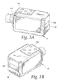
- FIGS. 3A and 3B illustrate a variation of FIGS. 2A and 2B;
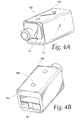
- FIGS. 4A and 4B illustrate yet another embodiment of the present invention where the jacket is a tube casing that surrounds the receiver;
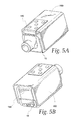
- FIGS. 5A and 5B illustrate yet another variation of FIGS. 3A and 3B;
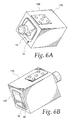
- FIGS. 6A and 6B illustrate another embodiment of the present invention where the jacket is made of epoxy
- FIGS. 7A and 7B illustrate yet a further embodiment of the present invention where an acoustic dampening material is located between the receiver than the jacket.
- FIGS. 8A and 8B illustrate a D-shaped receiver and jacket arrangement according one embodiment of the present invention.
- FIGS. 1A and 1B illustrate a first embodiment of the present invention.
- An acoustic receiver 10 includes various working components that convert an input audio signal into an acoustic signal. These working components typically include several electromagnetic components that move a drive element coupled to a diaphragm for creating the acoustic signal.
- the receiver 10 is a balanced armature receiver.
- An example of a receiver is disclosed in commonly assigned U.S. Patent No. 6,075,870, titled "Electroacoustic Transducer With Improved Shock Resistance,” which is incorporated herein by reference in its entirety.
- a housing 12 surrounds the working components and includes a case 14 and a cover 15 above the case 14.
- the housing 12 has six sides, each of which is generally rectangular. Of course, the housing 12 may take the form of various shapes (e.g., cylindrical, D-shaped, or trapezoid-shaped) with a different number of sides.
- One end surface of the housing 12 includes an output port 16 for transmitting the acoustical signal toward the listener's eardrum.
- Another end surface of the housing 12 includes an electrical connector assembly 18 that typically has two or three contacts on a printed circuit board. The electrical connector assembly 18 receives an input audio signal that is converted by the internal working components to an output acoustic signal that is broadcast from the output port 16.
- a jacket 20 has sections that cover three of the major side surfaces of the housing 12, and the end surface where the electrical connector assembly 18 is located. Each of the sections is generally flat and closely interfits with the corresponding one of the side surfaces of the housing 12.
- the jacket 20 can be made of a variety of materials that serve the purpose of increasing the structural integrity of the housing 12 and may also provide some level of electromagnetic shielding.
- the jacket 20 may be made of a soft magnetic material such as a nickel-iron alloy (usually the preferred material for the housing 12), stainless steel, or a polymeric material such as Kapton.
- the jacket 20 is stainless steel having a thickness of between approximately 0.05 mm and 0.2 mm, and is preconfigured to the disclosed shape. If a polymer is used, the polymer would typically have a thickness of 0.2 mm to 0.3 mm. After the receiver 12 has been fully assembled and tested, the jacket 20 is press-fit onto the housing 12. It may also be attached to the housing 12 via an adhesive.
- the receiver 10 By adding material to the outside of the housing 12, the receiver 10 is much more stiff and less prone to structural damage. Further, the additional mass from the jacket 20 reduces the vibration of the receiver 10, which decreases the vibrational feedback to the microphone to which the receiver 10 is coupled. If enhanced electromagnetic shielding is desired, the jacket 20 can be made of a material that provides this effect, such as a nickel-iron alloy.
- FIGS. 2A and 2B disclose another embodiment of the present invention.
- the receiver 10 includes a jacket 120 that is positioned to define a gap 122 between the housing 12 and the jacket 120.
- the jacket 120 is spot-welded to the housing 12.
- One set of welds 124 is located on the case 14 and another set of welds 126 is located on the cover 15. Accordingly, the jacket 120 may serve the additional purpose of holding the cover 15 on the case 14.
- the base of the output port 16, which straddles the case 14 and the cover 15, serves this purpose and in those situations, the output port 16 can be relieved of this function if the jacket 120 is used for this purpose.
- a flexible printed circuit board 130 (“flex-PCB”) is located within the gap 122.
- the flex-PCB 130 contains various signal processing components, which are located under the jacket 120.
- the flex-PCB 130 may contain an amplifier that receives the audio signal from a microphone that amplifies it before sending the signal into the receiver 10.
- the flex-PCB 130 also includes a plurality of electrical contacts 132 for receiving the audio signal directly from the microphone or indirectly through other signal processing circuitry.
- the gap 122 defined by the jacket 120 can be thought of as convenient location for the electronic circuitry in the system located between the microphone and the receiver 10. Accordingly, the flex-PCB 130 must be connected via leads to the electrical connector assembly 18 of the receiver to transmit the input audio signal. Those leads can be attached to the electrical contacts 132, or other electrical contacts located underneath the jacket 120. This embodiment is advantageous since it allows the receiver 10 to be fully tested and calibrated (if needed) and later assembled into the jacket 120 which, along with the flex-PCB 130, has other signal processing electronics.
- FIGS. 3A and 3B illustrate a variation of the embodiment of FIGS. 2A and 2B in that the gap 122 defined by the jacket 120 receives an extended flex-PCB 140.
- the extended flex-PCB 140 is directly connected to the electrical connector assembly 18, thereby eliminating the need for lead wires connecting the extended flex-PCB 140 to the electrical connector assembly 18.
- One other notable change from FIGS. 2A and 2B is that the jacket 120 is preconfigured to tightly fit over the extended flex-PCB 140 and the receiver 10 and may be held there with adhesive.
- FIG. 4A and 4B illustrate a jacket 150 in the form of a tubular casing.
- the jacket 150 includes four sides for closely interfitting with the housing 12 of the receiver 10. The four sides are contacting the housing 12 and are held on the housing 12 via a plurality of spot welds 152.
- the rear side 154 of the jacket 150 is partially opened to provide access to the electrical connector assembly 18 of the receiver 10.
- the jacket 150 lacks a gap to provide a region into which a flex-PCB can be placed. However, the jacket 150 could be configured in such a manner.
- FIGS. 5A and 5B illustrate a variation of the embodiment of FIGS. 3A and 3B.
- a jacket 160 includes three sides giving it a U-shaped cross-section. Accordingly, the jacket 160 lacks a rear section that fits over the flex-PCB 140 adjacent to the electrical connector assembly 18 of the receiver 10. Thus, the jacket 160 provides more access to this region of the receiver 10.
- FIGS. 6A and 6B depart from the previous embodiments where the jackets were preformed structures attached to the housing 12 of the receiver 10.
- an epoxy jacket 170 is placed over the receiver 10 and the extended flex-PCB 140, which is coupled to the electrical connector assembly 18 of the receiver 10.
- the epoxy jacket 170 could be used on a configuration similar to that of FIGS. 1A and 1B where there is no flex-PCB 140.
- the epoxy jacket 170 is shown having a uniform thickness.
- the epoxy layer comprising the jacket could be strategically placed in regions where the side walls of the housing 12 of the receiver 10 are known to vibrate more in operation. For example, the middle point of a side surface of the housing 12 will typically vibrate more and, thus, a thicker layer of epoxy could be applied there. In such a case, the final assembly may resemble more of an ellipsoid.
- the epoxy layer can be of varying thicknesses, but is usually between 0.25 mm and 1.0 mm. It can also be molded to a certain shape, such as a conical shape, to fit within the hearing aid or telecommunications system.
- the epoxy can be one of many types. For example, it can be 3AB of the 3M Corporation of Minneapolis, MN. It could also be configured to include metallic particles to provide electromagnetic shielding. Further, a first layer of epoxy could be placed on the housing 12. Then, a foil of soft magnetic material could be placed around the first layer. Finally, a second layer could be placed over the top of the foil. The foil would provide electromagnetic shielding; the epoxy would provide enhanced structural integrity.
- FIGS. 7A and 7B illustrate a further embodiment where a cylindrical jacket 180 has an acoustical dampening component 182 located thereunder.
- FIGS. 8A and 8B illustrate another embodiment where a D-shaped jacket 190 has an acoustical dampening component 192 located thereunder.
- the D-shaped jacket 190 has a D-shaped cross section.
- the cylindrical jacket 180 or D-shaped jacket 190 can be a soft magnetic material, stainless steel, or a polymer.
- the dampening components 182, 192 can be silicone or a resilient material such as C-Flex or Seal-Guard.
- the resilient material may be molded into a variety of shapes (even a custom-shaped mold) so that the receiver 10 fits nicely within a confined region of the hearing aid or telecommunication system.
- the cylindrical jacket 180 and the D-shaped jacket 190 respectively, provides structural integrity and also possible electromagnetic shielding.
- the dampening components 182, 192 provide acoustical and vibrational shielding. While these are the only embodiments where an additional dampening component is used, it can also be provided in a thin layer below the previous jackets. Usually, at least about 0.5 mm of the dampening component is needed to provide the desired results.
- the aforementioned jackets may also include a male or female mating structure that mates with a corresponding structure in the final assembly.
- the receiver can be slid into a mating fit within the assembly and rely on pressure for making electrical contact at the electrical connector assembly.
- the jacket may enhance the structural integrity, provide electromagnetic shielding, provide acoustical and vibrational shielding, and be used for mating with the final assembly.
- the D-shaped assembly shown in FIGS. 8A and 8B is easily transformed into a trapezoidal-shaped assembly by planing the top portion of the D-shaped jacket 190.
- the resulting assembly has a substantially trapezoidal-shaped cross section. It will be understood that the receiver 10 can be shaped into any geometry to fit within the D-shaped assembly.
- a microphone may be used in place of the receiver 10.
- the output port 16 is a sound inlet port for receiving an acoustical signal
- the internal working components include commonly-known components for converting the acoustical signal to an audio signal. Examples of these components are disclosed in commonly assigned U.S. Patent No. 6,169,810, titled “Electroacoustic Transducer,” which is incorporated herein by reference in its entirety.
- the jacket covering the microphone may provide any combination of structural integrity, electromagnetic shielding, or vibration reduction, for example.
- the jacket covering the microphone may include any combination of a polymeric material such as Kapton, stainless steel, a soft magnetic material such as a nickel-iron alloy, or an epoxy layer which may include metallic particles, for example.
- While the invention has been shown with respect to a six-sided receiver, it can also be used on receivers or microphones of varying shapes. For example, it could be used on a D-shaped receiver or microphone, a cylindrical receiver or microphone, a trapezoid-shaped receiver or microphone, or a generally oval-shaped receiver or microphone.
- any of the aforementioned jackets may be dimensioned to cover more than one receiver or microphone or combination of receivers and microphones.
- two or more receivers are stacked on top of one another, and a jacket is disposed over the receivers according to any of the foregoing embodiments.
- the receivers may be welded or adhered together.
- two or more receivers are placed side-by-side, and a jacket is disposed over the receivers according to any of the foregoing embodiments.
- one or more receivers and one or more microphones are either stacked on top one another or placed side-by-side, and a jacket is disposed thereover.
- the jacket operates to increase vibrational dampening and offers additional structural integrity to the multiple transducer arrangement.
Landscapes
- Engineering & Computer Science (AREA)
- Manufacturing & Machinery (AREA)
- Health & Medical Sciences (AREA)
- General Health & Medical Sciences (AREA)
- Neurosurgery (AREA)
- Otolaryngology (AREA)
- Physics & Mathematics (AREA)
- Acoustics & Sound (AREA)
- Signal Processing (AREA)
- Electrostatic, Electromagnetic, Magneto- Strictive, And Variable-Resistance Transducers (AREA)
- Structure Of Receivers (AREA)
- Shielding Devices Or Components To Electric Or Magnetic Fields (AREA)
Applications Claiming Priority (4)
| Application Number | Priority Date | Filing Date | Title |
|---|---|---|---|
| US25275600P | 2000-11-22 | 2000-11-22 | |
| US252756 | 2000-11-22 | ||
| US992253P | 2001-11-16 | ||
| US09/992,253 US7181035B2 (en) | 2000-11-22 | 2001-11-16 | Acoustical receiver housing for hearing aids |
Publications (3)
| Publication Number | Publication Date |
|---|---|
| EP1209948A2 true EP1209948A2 (de) | 2002-05-29 |
| EP1209948A3 EP1209948A3 (de) | 2006-07-12 |
| EP1209948B1 EP1209948B1 (de) | 2011-03-30 |
Family
ID=26942631
Family Applications (1)
| Application Number | Title | Priority Date | Filing Date |
|---|---|---|---|
| EP01204474A Expired - Lifetime EP1209948B1 (de) | 2000-11-22 | 2001-11-22 | Gehäuse für akustischen Empfänger für Hörhilfegeräte |
Country Status (5)
| Country | Link |
|---|---|
| US (2) | US7181035B2 (de) |
| EP (1) | EP1209948B1 (de) |
| AT (1) | ATE504168T1 (de) |
| DE (1) | DE60144320D1 (de) |
| DK (1) | DK1209948T3 (de) |
Cited By (11)
| Publication number | Priority date | Publication date | Assignee | Title |
|---|---|---|---|---|
| WO2007027152A1 (en) * | 2005-08-31 | 2007-03-08 | Siemens Audiologische Technik Gmbh | Receiver |
| EP1874090A1 (de) * | 2006-06-28 | 2008-01-02 | Siemens Audiologische Technik GmbH | Hörhilfsgerät |
| EP2003932A1 (de) * | 2007-06-15 | 2008-12-17 | Siemens Medical Instruments Pte. Ltd. | Zylinderförmiges Hörgerät |
| EP1978783A3 (de) * | 2007-04-04 | 2011-01-12 | Siemens Hearing Instruments, Inc. | Herstellung eines Im-Ohr-Hörgeräts mit Empfängerabteilung |
| WO2012104142A1 (en) | 2011-02-01 | 2012-08-09 | Phonak Ag | Hearing device with a transducer module and method for manufacturing a transducer module |
| US8798299B1 (en) | 2008-12-31 | 2014-08-05 | Starkey Laboratories, Inc. | Magnetic shielding for communication device applications |
| US8861761B2 (en) | 2007-09-19 | 2014-10-14 | Starkey Laboratories, Inc. | System for hearing assistance device including receiver in the canal |
| WO2015010716A1 (en) | 2013-07-22 | 2015-01-29 | Phonak Ag | Hearing device with improved low frequency response and method for manufacturing such a hearing device |
| US9002047B2 (en) | 2009-07-23 | 2015-04-07 | Starkey Laboratories, Inc. | Method and apparatus for an insulated electromagnetic shield for use in hearing assistance devices |
| US9693154B2 (en) | 2008-08-27 | 2017-06-27 | Starkey Laboratories, Inc. | Modular connection assembly for a hearing assistance device |
| US10051390B2 (en) | 2008-08-11 | 2018-08-14 | Starkey Laboratories, Inc. | Hearing aid adapted for embedded electronics |
Families Citing this family (91)
| Publication number | Priority date | Publication date | Assignee | Title |
|---|---|---|---|---|
| US7181035B2 (en) * | 2000-11-22 | 2007-02-20 | Sonion Nederland B.V. | Acoustical receiver housing for hearing aids |
| US7088839B2 (en) * | 2001-04-04 | 2006-08-08 | Sonion Nederland B.V. | Acoustic receiver having improved mechanical suspension |
| DE10223544C1 (de) * | 2002-05-27 | 2003-07-24 | Siemens Audiologische Technik | Vorrichtung und Verfahren zur Feedbackreduktion bei Hörsystemen |
| US7072482B2 (en) | 2002-09-06 | 2006-07-04 | Sonion Nederland B.V. | Microphone with improved sound inlet port |
| US7460681B2 (en) * | 2004-07-20 | 2008-12-02 | Sonion Nederland B.V. | Radio frequency shielding for receivers within hearing aids and listening devices |
| US20060058573A1 (en) * | 2004-09-16 | 2006-03-16 | Neisz Johann J | Method and apparatus for vibrational damping of implantable hearing aid components |
| US8170249B2 (en) † | 2006-06-19 | 2012-05-01 | Sonion Nederland B.V. | Hearing aid having two receivers each amplifying a different frequency range |
| US8693720B2 (en) * | 2006-08-31 | 2014-04-08 | Red Tail Hawk Corporation | Wireless earplug with improved sensitivity and form factor |
| US8688036B2 (en) * | 2006-08-31 | 2014-04-01 | Red Tail Hawk Corporation | Wireless communications headset system employing a loop transmitter that fits around the pinna |
| US9525930B2 (en) | 2006-08-31 | 2016-12-20 | Red Tail Hawk Corporation | Magnetic field antenna |
| USD588584S1 (en) * | 2007-01-17 | 2009-03-17 | Samsung Electronics Co., Ltd. | Microphone with clip |
| DE102007031872B4 (de) * | 2007-07-09 | 2009-11-19 | Siemens Audiologische Technik Gmbh | Hörgerät |
| US8135163B2 (en) * | 2007-08-30 | 2012-03-13 | Klipsch Group, Inc. | Balanced armature with acoustic low pass filter |
| US8218801B2 (en) * | 2008-05-30 | 2012-07-10 | Symbol Technologies, Inc. | Method and system for a headset H-field/E-field canceller |
| US20100135513A1 (en) * | 2008-12-01 | 2010-06-03 | Sonion Nederland B.V. | Radio frequency shielding for receivers within hearing aids and listening devices |
| CN101958597B (zh) * | 2009-07-15 | 2013-11-06 | 鸿富锦精密工业(深圳)有限公司 | 电磁屏蔽材料、电磁屏蔽壳和音圈马达 |
| JP5671929B2 (ja) * | 2010-10-12 | 2015-02-18 | ソニー株式会社 | イヤホン、音響変換装置 |
| US8712084B2 (en) | 2010-12-07 | 2014-04-29 | Sonion Nederland Bv | Motor assembly |
| EP2469705B1 (de) | 2010-12-21 | 2015-12-02 | Sonion Nederland B.V. | Erzeugung einer Versorgungsspannung aus dem Ausgangssignal eines Class-D Audio-Verstärkers |
| DK2730097T3 (en) | 2011-07-07 | 2019-12-09 | Sonion Nederland Bv | A multiple receiver assembly and a method for assembly thereof |
| DE112012003755T5 (de) * | 2011-09-09 | 2014-09-18 | Knowles Electronics, Llc | HF-Abschirmung für akustische Einrichtungen |
| USD698025S1 (en) * | 2011-12-15 | 2014-01-21 | Widex A/S | Hearing aid |
| US8983101B2 (en) | 2012-05-22 | 2015-03-17 | Shure Acquisition Holdings, Inc. | Earphone assembly |
| US9083388B2 (en) | 2012-08-29 | 2015-07-14 | Red Tail Hawk Corporation | Transmitter with improved sensitivity and shielding |
| EP2723102B1 (de) | 2012-10-18 | 2018-09-05 | Sonion Nederland B.V. | Wandler, Hörgerät mit dem Wandler und Verfahren zum Betrieb des Wandlers |
| US9066187B2 (en) | 2012-10-18 | 2015-06-23 | Sonion Nederland Bv | Dual transducer with shared diaphragm |
| DK2747459T3 (en) | 2012-12-21 | 2018-12-17 | Sonion Nederland Bv | RIC unit with Thuras tube |
| DK2750413T3 (en) | 2012-12-28 | 2017-05-22 | Sonion Nederland Bv | Hearing aid |
| US9401575B2 (en) | 2013-05-29 | 2016-07-26 | Sonion Nederland Bv | Method of assembling a transducer assembly |
| DK2849463T3 (en) | 2013-09-16 | 2018-06-25 | Sonion Nederland Bv | Transducer with moisture transporting element |
| US9326074B2 (en) * | 2013-09-24 | 2016-04-26 | Knowles Electronics, Llc | Increased compliance flat reed transducer |
| DK3550852T3 (en) | 2014-02-14 | 2021-02-01 | Sonion Nederland Bv | A joiner for a receiver assembly |
| EP2908559B1 (de) | 2014-02-18 | 2016-10-05 | Sonion A/S | Verfahren zur Herstellung von Anordnungen für Hörgeräte |
| EP2914018B1 (de) | 2014-02-26 | 2016-11-09 | Sonion Nederland B.V. | Lautsprecher, verankerung und verfahren |
| US9432774B2 (en) | 2014-04-02 | 2016-08-30 | Sonion Nederland B.V. | Transducer with a bent armature |
| EP2953380A1 (de) | 2014-06-04 | 2015-12-09 | Sonion Nederland B.V. | Akustische Übersprechkompensation |
| US20160119727A1 (en) * | 2014-10-27 | 2016-04-28 | Sidney A. Higgins | Sinter bonded mu-metal receiver can |
| US9888322B2 (en) | 2014-12-05 | 2018-02-06 | Knowles Electronics, Llc | Receiver with coil wound on a stationary ferromagnetic core |
| CN104394493A (zh) * | 2014-12-16 | 2015-03-04 | 苏州赫里翁电子科技有限公司 | 一种受话器壳体 |
| US9729974B2 (en) | 2014-12-30 | 2017-08-08 | Sonion Nederland B.V. | Hybrid receiver module |
| EP3051841B1 (de) * | 2015-01-30 | 2020-10-07 | Sonion Nederland B.V. | Hörer mit aufgehängter motoranordnung |
| DK3057339T3 (da) | 2015-02-10 | 2021-01-04 | Sonion Nederland Bv | Mikrofonmodul med fælles midterste lydindgangsanordning |
| EP3073764B1 (de) | 2015-03-25 | 2021-04-21 | Sonion Nederland B.V. | Hörgerät mit einem einsatzelement |
| EP3073765B1 (de) | 2015-03-25 | 2022-08-17 | Sonion Nederland B.V. | Anordnung eines hörers in einem gehörgang mit einer membran und einer kabelverbindung |
| DK3133829T3 (da) | 2015-08-19 | 2020-06-22 | Sonion Nederland Bv | Lydgiverenhed med forbedret frekvensrespons |
| DK3139627T3 (da) | 2015-09-02 | 2019-05-20 | Sonion Nederland Bv | Høreanordning med flervejslydgivere |
| US9668065B2 (en) | 2015-09-18 | 2017-05-30 | Sonion Nederland B.V. | Acoustical module with acoustical filter |
| US10021494B2 (en) | 2015-10-14 | 2018-07-10 | Sonion Nederland B.V. | Hearing device with vibration sensitive transducer |
| DK3160157T3 (en) | 2015-10-21 | 2018-12-17 | Sonion Nederland Bv | Vibration-compensated vibroacoustic device |
| DK3177037T3 (en) | 2015-12-04 | 2020-10-26 | Sonion Nederland Bv | Balanced armature receiver with bi-stable balanced armature |
| DK3185584T3 (da) | 2015-12-21 | 2020-07-20 | Sonion Nederland Bv | Lydgiveranordning med en udpræget længderetning |
| EP3197046B1 (de) | 2016-01-25 | 2021-04-14 | Sonion Nederland B.V. | Selbstvorspannender ausgangsboosterverstärker und verwendung davon |
| EP3200479A3 (de) | 2016-01-28 | 2017-08-30 | Sonion Nederland B.V. | Elektrostatischer schallgenerator und anordnung mit elektrostatischem schallgenerator und transformator |
| EP3232685B1 (de) | 2016-04-13 | 2021-03-03 | Sonion Nederland B.V. | Kuppel für eine persönliche audio-nachrichtenvorrichtung |
| US10078097B2 (en) | 2016-06-01 | 2018-09-18 | Sonion Nederland B.V. | Vibration or acceleration sensor applying squeeze film damping |
| DK3279621T4 (da) | 2016-08-26 | 2025-04-28 | Sonion Nederland Bv | Vibrationssensor med lavfrekvent roll-off-responskurve |
| EP3293985B1 (de) | 2016-09-12 | 2021-03-24 | Sonion Nederland B.V. | Hörer mit integrierter membranbewegungserkennung |
| DK3313097T3 (da) | 2016-10-19 | 2020-10-19 | Sonion Nederland Bv | An ear bud or dome |
| US10264361B2 (en) | 2016-11-18 | 2019-04-16 | Sonion Nederland B.V. | Transducer with a high sensitivity |
| EP3324645A1 (de) | 2016-11-18 | 2018-05-23 | Sonion Nederland B.V. | Phasenkorrigierendes system und phasenkorrigierbares wandlersystem |
| EP3324538A1 (de) | 2016-11-18 | 2018-05-23 | Sonion Nederland B.V. | Messschaltung mit einer verstärkerschaltung |
| US20180145643A1 (en) | 2016-11-18 | 2018-05-24 | Sonion Nederland B.V. | Circuit for providing a high and a low impedance and a system comprising the circuit |
| EP3337184B1 (de) | 2016-12-14 | 2020-03-25 | Sonion Nederland B.V. | Anker und wandler mit dem anker |
| US10405085B2 (en) | 2016-12-16 | 2019-09-03 | Sonion Nederland B.V. | Receiver assembly |
| EP3337191B1 (de) * | 2016-12-16 | 2021-05-19 | Sonion Nederland B.V. | Schallerzeugeranordnung |
| US10699833B2 (en) | 2016-12-28 | 2020-06-30 | Sonion Nederland B.V. | Magnet assembly |
| US10477308B2 (en) | 2016-12-30 | 2019-11-12 | Sonion Nederland B.V. | Circuit and a receiver comprising the circuit |
| EP3342749A3 (de) | 2016-12-30 | 2018-09-12 | Sonion Nederland B.V. | Mikroelektromechanischer wandler |
| DK3407625T3 (en) | 2017-05-26 | 2021-07-12 | Sonion Nederland Bv | Receiver with venting opening |
| US10721566B2 (en) | 2017-05-26 | 2020-07-21 | Sonion Nederland B.V. | Receiver assembly comprising an armature and a diaphragm |
| EP3429231B1 (de) | 2017-07-13 | 2023-01-25 | Sonion Nederland B.V. | Hörgerät mit einrichtung zur vibrationsvermeidung |
| US10820104B2 (en) | 2017-08-31 | 2020-10-27 | Sonion Nederland B.V. | Diaphragm, a sound generator, a hearing device and a method |
| EP3451688B1 (de) | 2017-09-04 | 2021-05-26 | Sonion Nederland B.V. | Schallerzeuger, abschirmung und öffnung |
| GB201714956D0 (en) | 2017-09-18 | 2017-11-01 | Sonova Ag | Hearing device with adjustable venting |
| DK3471432T3 (da) | 2017-10-16 | 2022-10-24 | Sonion Nederland Bv | Lydkanalelement med en ventil og en transducer med lydkanalelementet |
| EP3471437B1 (de) | 2017-10-16 | 2020-12-23 | Sonion Nederland B.V. | Ventil, wandler mit einem ventil, hörgerät und verfahren |
| US10945084B2 (en) | 2017-10-16 | 2021-03-09 | Sonion Nederland B.V. | Personal hearing device |
| DK3567873T3 (en) | 2018-02-06 | 2021-11-15 | Sonion Nederland Bv | Method for controlling an acoustic valve of a hearing device |
| EP3531713B1 (de) | 2018-02-26 | 2022-11-02 | Sonion Nederland B.V. | Miniaturlautsprecher mit akustischer masse |
| DK3531720T3 (da) | 2018-02-26 | 2021-11-15 | Sonion Nederland Bv | Anordning af en lydgiver og en mikrofon |
| EP3467457B1 (de) | 2018-04-30 | 2022-07-20 | Sonion Nederland B.V. | Vibrationssensor |
| DK3579578T3 (da) | 2018-06-07 | 2022-05-02 | Sonion Nederland Bv | Miniaturelydgiver |
| US10951169B2 (en) | 2018-07-20 | 2021-03-16 | Sonion Nederland B.V. | Amplifier comprising two parallel coupled amplifier units |
| DE102018214322A1 (de) * | 2018-08-24 | 2020-02-27 | Sivantos Pte. Ltd. | Dämpfungseinrichtung für einen Hörer eines Hörinstruments sowie Hörinstrument mit einer solchen Dämpfungseinrichtung |
| DK3627856T3 (da) | 2018-09-19 | 2023-11-13 | Sonion Nederland Bv | Hus, der omfatter en sensor |
| EP4300995A3 (de) | 2018-12-19 | 2024-04-03 | Sonion Nederland B.V. | Miniaturlautsprecher mit mehreren schallhohlräumen |
| EP3675522A1 (de) | 2018-12-28 | 2020-07-01 | Sonion Nederland B.V. | Miniaturlautsprecher ohne wesentliche akustische leckage |
| US11190880B2 (en) | 2018-12-28 | 2021-11-30 | Sonion Nederland B.V. | Diaphragm assembly, a transducer, a microphone, and a method of manufacture |
| EP3726855B1 (de) | 2019-04-15 | 2021-09-01 | Sonion Nederland B.V. | Persönliches hörgerät mit entlüftungskanal und akustischer trennung |
| USD920287S1 (en) * | 2019-05-07 | 2021-05-25 | MBRIO Technologies LLC | Set of prenatal earbud adapters |
| EP3806494B1 (de) | 2019-10-07 | 2023-12-27 | Sonion Nederland B.V. | Hörgerät mit einem optischen sensor |
Family Cites Families (47)
| Publication number | Priority date | Publication date | Assignee | Title |
|---|---|---|---|---|
| US3048668A (en) * | 1961-04-17 | 1962-08-07 | Beltone Hearing Aid Company | Transducer suspension system |
| US3257516A (en) * | 1962-06-25 | 1966-06-21 | Knowles Electronies Inc | Combined instrument and transducer motor cavities for acoustic instrument |
| US3588383A (en) * | 1970-02-09 | 1971-06-28 | Industrial Research Prod Inc | Miniature acoustic transducer of improved construction |
| US3671684A (en) * | 1970-11-06 | 1972-06-20 | Tibbetts Industries | Magnetic transducer |
| DE2346531A1 (de) | 1973-09-15 | 1975-04-03 | Micro Technic Hueber & Co | Hoerhilfsgeraet fuer schwerhoerige oder hoerbehinderte |
| US4081782A (en) | 1976-08-04 | 1978-03-28 | Bourns, Inc. | Combined rotary potentiometer and switch |
| US4272654A (en) * | 1979-01-08 | 1981-06-09 | Industrial Research Products, Inc. | Acoustic transducer of improved construction |
| NL8101286A (nl) * | 1981-03-17 | 1982-10-18 | Philips Nv | Verbeterde ophanging voor een telefoon in een hoorapparaat. |
| JPH0312000Y2 (de) * | 1981-04-20 | 1991-03-22 | ||
| US4430520A (en) * | 1982-04-07 | 1984-02-07 | Tibbetts Industries, Inc. | Transducer shielding enclosure |
| US4520236A (en) * | 1983-11-30 | 1985-05-28 | Nu-Bar Electronics | Sound transfer from a hearing aid to the human ear drum |
| CA1235791A (en) * | 1984-01-04 | 1988-04-26 | Gordon B. Gore | Suspension for electro-acoustical transducers |
| CH662026A5 (de) | 1984-02-21 | 1987-08-31 | Gfeller Ag | In-dem-ohr-hoergeraet. |
| US4729451A (en) * | 1984-05-30 | 1988-03-08 | Beltone Electronics, Corporation | Receiver suspension and acoustic porting system |
| DE8613349U1 (de) * | 1986-05-16 | 1987-10-29 | Siemens AG, 1000 Berlin und 8000 München | Halterung für einen Hörer |
| USRE33718E (en) * | 1986-09-15 | 1991-10-15 | Knowles Electronics, Inc. | Acoustic transducer with improved electrode spacing |
| DE8704315U1 (de) * | 1987-03-23 | 1987-05-27 | Siemens AG, 1000 Berlin und 8000 München | Hörgerät, dessen Bauelemente in einem Hörgerätgehäuse gehaltert sind |
| DE8804743U1 (de) | 1988-04-11 | 1989-08-10 | Siemens AG, 1000 Berlin und 8000 München | Hörhilfegerät, insbesondere Hörgerät mit einem hinter dem Ohr zu tragenden Gehäuse |
| DE58906141D1 (de) | 1988-07-04 | 1993-12-16 | Siemens Audiologische Technik | Hörgerät. |
| US4969534A (en) | 1988-08-08 | 1990-11-13 | Minnesota Mining And Manufacturing Company | Hearing aid employing a viscoelastic material to adhere components to the casing |
| EP0416155A1 (de) | 1989-09-07 | 1991-03-13 | Siemens Aktiengesellschaft | Hinter dem Ohr zu tragendes Hörgerät |
| GB8928899D0 (en) * | 1989-12-21 | 1990-02-28 | Knowles Electronics Co | Coil assemblies |
| CA2014960C (en) * | 1990-04-19 | 1995-07-25 | Horst Arndt | Modular hearing aid |
| DE4121449A1 (de) * | 1991-06-28 | 1993-01-07 | Siemens Ag | Hoergeraet, insbesondere am kopf tragbares mini-hoergeraet, und verfahren zur herstellung |
| US5193116A (en) * | 1991-09-13 | 1993-03-09 | Knowles Electronics, Inc. | Hearing and output transducer with self contained amplifier |
| US5220612A (en) * | 1991-12-20 | 1993-06-15 | Tibbetts Industries, Inc. | Non-occludable transducers for in-the-ear applications |
| US5335286A (en) * | 1992-02-18 | 1994-08-02 | Knowles Electronics, Inc. | Electret assembly |
| US5887070A (en) * | 1992-05-08 | 1999-03-23 | Etymotic Research, Inc. | High fidelity insert earphones and methods of making same |
| AU4391393A (en) | 1992-05-26 | 1993-12-30 | Bausch & Lomb Incorporated | Soft earshell for hearing aids |
| EP0589308B1 (de) | 1992-09-23 | 1997-12-03 | Siemens Audiologische Technik GmbH | Hörgerät |
| EP0716800A1 (de) | 1993-09-01 | 1996-06-19 | Knowles Electronics, Inc. | Empfänger für ein hörhilfegerät |
| US5692060A (en) * | 1995-05-01 | 1997-11-25 | Knowles Electronics, Inc. | Unidirectional microphone |
| GB2305067A (en) | 1995-09-02 | 1997-03-26 | A & M Hearing Ltd | Hearing aid having hinged housing |
| US5881159A (en) | 1996-03-14 | 1999-03-09 | Sarnoff Corporation | Disposable hearing aid |
| NL1002880C2 (nl) | 1996-04-16 | 1997-10-17 | Microtronic Nederland Bv | Elektroakoestische transducent. |
| DE29608215U1 (de) * | 1996-05-06 | 1996-08-01 | Siemens Audiologische Technik Gmbh, 91058 Erlangen | Elektrisches Hörhilfegerät |
| US5740261A (en) * | 1996-11-21 | 1998-04-14 | Knowles Electronics, Inc. | Miniature silicon condenser microphone |
| NL1004877C2 (nl) * | 1996-12-23 | 1998-08-03 | Microtronic Nederland Bv | Elektroakoestische transducent. |
| WO2000042815A1 (en) | 1999-01-15 | 2000-07-20 | Sonic Innovations | Conformal tip for a hearing aid |
| ATE499806T1 (de) | 1999-06-16 | 2011-03-15 | Phonak Ag | Hinterohr-hörgerät |
| CA2377444C (en) | 1999-06-16 | 2009-04-14 | Erich Dittli | Behind-the-ear hearing aid |
| DE19954880C1 (de) | 1999-11-15 | 2001-01-25 | Siemens Audiologische Technik | Elektromagnetischer Wandler zur Schallerzeugung in Hörhilfen, insbesondere miniaturisierten elektronischen Hörgeräten |
| WO2001043498A1 (en) | 1999-12-10 | 2001-06-14 | Sonic Innovations, Inc. | Receiver suspension device for an in-the-canal hearing aid |
| US6456720B1 (en) * | 1999-12-10 | 2002-09-24 | Sonic Innovations | Flexible circuit board assembly for a hearing aid |
| AU2001245773A1 (en) * | 2000-03-15 | 2001-09-24 | Knowles Electronics, Llc. | Vibration-dampening receiver assembly |
| US7181035B2 (en) | 2000-11-22 | 2007-02-20 | Sonion Nederland B.V. | Acoustical receiver housing for hearing aids |
| US7088839B2 (en) | 2001-04-04 | 2006-08-08 | Sonion Nederland B.V. | Acoustic receiver having improved mechanical suspension |
-
2001
- 2001-11-16 US US09/992,253 patent/US7181035B2/en not_active Expired - Lifetime
- 2001-11-22 DE DE60144320T patent/DE60144320D1/de not_active Expired - Lifetime
- 2001-11-22 DK DK01204474.9T patent/DK1209948T3/da active
- 2001-11-22 EP EP01204474A patent/EP1209948B1/de not_active Expired - Lifetime
- 2001-11-22 AT AT01204474T patent/ATE504168T1/de not_active IP Right Cessation
-
2006
- 2006-12-06 US US11/634,586 patent/US7657048B2/en not_active Expired - Lifetime
Non-Patent Citations (1)
| Title |
|---|
| None |
Cited By (23)
| Publication number | Priority date | Publication date | Assignee | Title |
|---|---|---|---|---|
| WO2007027152A1 (en) * | 2005-08-31 | 2007-03-08 | Siemens Audiologische Technik Gmbh | Receiver |
| EP1874090A1 (de) * | 2006-06-28 | 2008-01-02 | Siemens Audiologische Technik GmbH | Hörhilfsgerät |
| EP1978783A3 (de) * | 2007-04-04 | 2011-01-12 | Siemens Hearing Instruments, Inc. | Herstellung eines Im-Ohr-Hörgeräts mit Empfängerabteilung |
| US8068631B2 (en) | 2007-04-04 | 2011-11-29 | Siemens Hearing Instruments Inc. | Construction of a completely-in-canal hearing instrument with receiver compartment |
| EP2003932A1 (de) * | 2007-06-15 | 2008-12-17 | Siemens Medical Instruments Pte. Ltd. | Zylinderförmiges Hörgerät |
| US8861761B2 (en) | 2007-09-19 | 2014-10-14 | Starkey Laboratories, Inc. | System for hearing assistance device including receiver in the canal |
| US11064304B2 (en) | 2008-08-11 | 2021-07-13 | Starkey Laboratories, Inc. | Hearing aid adapted for embedded electronics |
| US11765531B2 (en) | 2008-08-11 | 2023-09-19 | Starkey Laboratories, Inc. | Hearing aid adapted for embedded electronics |
| US12302071B2 (en) | 2008-08-11 | 2025-05-13 | Starkey Laboratories, Inc. | Hearing aid adapted for embedded electronics |
| US10051390B2 (en) | 2008-08-11 | 2018-08-14 | Starkey Laboratories, Inc. | Hearing aid adapted for embedded electronics |
| US10448176B2 (en) | 2008-08-11 | 2019-10-15 | Starkey Laboratories, Inc. | Hearing aid adapted for embedded electronics |
| US12120487B2 (en) | 2008-08-27 | 2024-10-15 | Starkey Laboratories, Inc. | Modular connection assembly for a hearing assistance device |
| US11711660B2 (en) | 2008-08-27 | 2023-07-25 | Starkey Laboratories, Inc. | Modular connection assembly for a hearing assistance device |
| US9693154B2 (en) | 2008-08-27 | 2017-06-27 | Starkey Laboratories, Inc. | Modular connection assembly for a hearing assistance device |
| US11252521B2 (en) | 2008-08-27 | 2022-02-15 | Starkey Laboratories, Inc. | Modular connection assembly for a hearing assistance device |
| US10257622B2 (en) | 2008-08-27 | 2019-04-09 | Starkey Laboratories, Inc. | Modular connection assembly for a hearing assistance device |
| US8798299B1 (en) | 2008-12-31 | 2014-08-05 | Starkey Laboratories, Inc. | Magnetic shielding for communication device applications |
| US9002047B2 (en) | 2009-07-23 | 2015-04-07 | Starkey Laboratories, Inc. | Method and apparatus for an insulated electromagnetic shield for use in hearing assistance devices |
| EP2278828B1 (de) * | 2009-07-23 | 2017-09-06 | Starkey Laboratories, Inc. | Verfahren und Vorrichtung für eine isolierte elektromagnetische Abschirmung zur Verwendung in Hörhilfevorrichtungen |
| US9571943B2 (en) | 2011-02-01 | 2017-02-14 | Sonova Ag | Hearing device with a transducer module and method for manufacturing a transducer module |
| WO2012103935A1 (en) | 2011-02-01 | 2012-08-09 | Phonak Ag | Hearing device with a receiver module and method for manufacturing a receiver module |
| WO2012104142A1 (en) | 2011-02-01 | 2012-08-09 | Phonak Ag | Hearing device with a transducer module and method for manufacturing a transducer module |
| WO2015010716A1 (en) | 2013-07-22 | 2015-01-29 | Phonak Ag | Hearing device with improved low frequency response and method for manufacturing such a hearing device |
Also Published As
| Publication number | Publication date |
|---|---|
| EP1209948A3 (de) | 2006-07-12 |
| US7657048B2 (en) | 2010-02-02 |
| DE60144320D1 (de) | 2011-05-12 |
| ATE504168T1 (de) | 2011-04-15 |
| US20070127744A1 (en) | 2007-06-07 |
| DK1209948T3 (da) | 2011-05-16 |
| EP1209948B1 (de) | 2011-03-30 |
| US20020061113A1 (en) | 2002-05-23 |
| US7181035B2 (en) | 2007-02-20 |
Similar Documents
| Publication | Publication Date | Title |
|---|---|---|
| US7181035B2 (en) | Acoustical receiver housing for hearing aids | |
| US7292700B1 (en) | Microphone for a hearing aid | |
| US6324907B1 (en) | Flexible substrate transducer assembly | |
| US7336797B2 (en) | Apparatus and method for generating acoustic energy in a receiver assembly | |
| US8041064B2 (en) | Card type MEMS microphone | |
| EP1425934B1 (de) | Miniaturlautsprecher mit integrierter signalverarbeitungselektronik | |
| JP3971763B2 (ja) | エレクトレットコンデンサーマイクロホン | |
| EP1397023A2 (de) | Mikrofon mit verbessertem Klangeinlasskanal | |
| US20210092509A1 (en) | Sound transducer unit for generating and/or detecting sound waves in the audible wavelength spectrum and/or in the ultrasonic range | |
| EP3101914B1 (de) | Mikrofonaufbau mit eingebetteter akustiköffnung | |
| US5889873A (en) | Piezoelectric acoustic transducer | |
| EP0077228B1 (de) | Elektroakustischer Wandler | |
| US8831259B2 (en) | Hearing aid faceplate arrangement | |
| EP2786592B1 (de) | Elektroakustischer wandler zur montage auf einem substrat | |
| US20060120541A1 (en) | Combined microphone-loudspeaker | |
| KR100629688B1 (ko) | 전면음 단일지향성 마이크로폰 | |
| EP4440143A1 (de) | Hörgerät | |
| US12212919B2 (en) | Ear-worn hearing device with multiple transducers | |
| US20240179481A1 (en) | Small meander line antenna for in-the-ear hearing device | |
| CN115348499B (zh) | 接收器和话筒的组件 | |
| JPS626400B2 (de) | ||
| WO1986006918A1 (en) | Improvements in or relating to microphones | |
| JP2008131624A (ja) | 通話装置 | |
| KR20060099309A (ko) | 단일 지향성 초소형 콘덴서 마이크로폰 및 그 조립방법 |
Legal Events
| Date | Code | Title | Description |
|---|---|---|---|
| PUAI | Public reference made under article 153(3) epc to a published international application that has entered the european phase |
Free format text: ORIGINAL CODE: 0009012 |
|
| AK | Designated contracting states |
Kind code of ref document: A2 Designated state(s): AT BE CH CY DE DK ES FI FR GB GR IE IT LI LU MC NL PT SE TR |
|
| AX | Request for extension of the european patent |
Free format text: AL;LT;LV;MK;RO;SI |
|
| RIN1 | Information on inventor provided before grant (corrected) |
Inventor name: VAN HAL, PAUL CHRISTIAAN Inventor name: VAN HALTEREN, AART ZEGER |
|
| RAP1 | Party data changed (applicant data changed or rights of an application transferred) |
Owner name: SONIONMICROTRONIC NETHERLAND B.V. |
|
| RAP1 | Party data changed (applicant data changed or rights of an application transferred) |
Owner name: SONIONMICROTRONIC NEDERLAND B.V. |
|
| PUAL | Search report despatched |
Free format text: ORIGINAL CODE: 0009013 |
|
| AK | Designated contracting states |
Kind code of ref document: A3 Designated state(s): AT BE CH CY DE DK ES FI FR GB GR IE IT LI LU MC NL PT SE TR |
|
| AX | Request for extension of the european patent |
Extension state: AL LT LV MK RO SI |
|
| 17P | Request for examination filed |
Effective date: 20070112 |
|
| AKX | Designation fees paid |
Designated state(s): AT BE CH CY DE DK ES FI FR GB GR IE IT LI LU MC NL PT SE TR |
|
| 17Q | First examination report despatched |
Effective date: 20081229 |
|
| RAP1 | Party data changed (applicant data changed or rights of an application transferred) |
Owner name: SONION NEDERLAND B.V. |
|
| GRAP | Despatch of communication of intention to grant a patent |
Free format text: ORIGINAL CODE: EPIDOSNIGR1 |
|
| GRAS | Grant fee paid |
Free format text: ORIGINAL CODE: EPIDOSNIGR3 |
|
| GRAA | (expected) grant |
Free format text: ORIGINAL CODE: 0009210 |
|
| AK | Designated contracting states |
Kind code of ref document: B1 Designated state(s): AT BE CH CY DE DK ES FI FR GB GR IE IT LI LU MC NL PT SE TR |
|
| REG | Reference to a national code |
Ref country code: GB Ref legal event code: FG4D |
|
| REG | Reference to a national code |
Ref country code: CH Ref legal event code: EP |
|
| REG | Reference to a national code |
Ref country code: IE Ref legal event code: FG4D |
|
| REG | Reference to a national code |
Ref country code: CH Ref legal event code: NV Representative=s name: MICHELI & CIE SA |
|
| REF | Corresponds to: |
Ref document number: 60144320 Country of ref document: DE Date of ref document: 20110512 Kind code of ref document: P |
|
| REG | Reference to a national code |
Ref country code: DE Ref legal event code: R096 Ref document number: 60144320 Country of ref document: DE Effective date: 20110512 |
|
| REG | Reference to a national code |
Ref country code: DK Ref legal event code: T3 |
|
| REG | Reference to a national code |
Ref country code: GB Ref legal event code: 732E Free format text: REGISTERED BETWEEN 20110505 AND 20110511 |
|
| REG | Reference to a national code |
Ref country code: NL Ref legal event code: VDEP Effective date: 20110330 |
|
| PG25 | Lapsed in a contracting state [announced via postgrant information from national office to epo] |
Ref country code: SE Free format text: LAPSE BECAUSE OF FAILURE TO SUBMIT A TRANSLATION OF THE DESCRIPTION OR TO PAY THE FEE WITHIN THE PRESCRIBED TIME-LIMIT Effective date: 20110330 Ref country code: GR Free format text: LAPSE BECAUSE OF FAILURE TO SUBMIT A TRANSLATION OF THE DESCRIPTION OR TO PAY THE FEE WITHIN THE PRESCRIBED TIME-LIMIT Effective date: 20110701 |
|
| PG25 | Lapsed in a contracting state [announced via postgrant information from national office to epo] |
Ref country code: CY Free format text: LAPSE BECAUSE OF FAILURE TO SUBMIT A TRANSLATION OF THE DESCRIPTION OR TO PAY THE FEE WITHIN THE PRESCRIBED TIME-LIMIT Effective date: 20110330 Ref country code: AT Free format text: LAPSE BECAUSE OF FAILURE TO SUBMIT A TRANSLATION OF THE DESCRIPTION OR TO PAY THE FEE WITHIN THE PRESCRIBED TIME-LIMIT Effective date: 20110330 Ref country code: FI Free format text: LAPSE BECAUSE OF FAILURE TO SUBMIT A TRANSLATION OF THE DESCRIPTION OR TO PAY THE FEE WITHIN THE PRESCRIBED TIME-LIMIT Effective date: 20110330 |
|
| PG25 | Lapsed in a contracting state [announced via postgrant information from national office to epo] |
Ref country code: BE Free format text: LAPSE BECAUSE OF FAILURE TO SUBMIT A TRANSLATION OF THE DESCRIPTION OR TO PAY THE FEE WITHIN THE PRESCRIBED TIME-LIMIT Effective date: 20110330 |
|
| PG25 | Lapsed in a contracting state [announced via postgrant information from national office to epo] |
Ref country code: PT Free format text: LAPSE BECAUSE OF FAILURE TO SUBMIT A TRANSLATION OF THE DESCRIPTION OR TO PAY THE FEE WITHIN THE PRESCRIBED TIME-LIMIT Effective date: 20110801 |
|
| PG25 | Lapsed in a contracting state [announced via postgrant information from national office to epo] |
Ref country code: ES Free format text: LAPSE BECAUSE OF FAILURE TO SUBMIT A TRANSLATION OF THE DESCRIPTION OR TO PAY THE FEE WITHIN THE PRESCRIBED TIME-LIMIT Effective date: 20110711 |
|
| PG25 | Lapsed in a contracting state [announced via postgrant information from national office to epo] |
Ref country code: NL Free format text: LAPSE BECAUSE OF FAILURE TO SUBMIT A TRANSLATION OF THE DESCRIPTION OR TO PAY THE FEE WITHIN THE PRESCRIBED TIME-LIMIT Effective date: 20110330 |
|
| PGFP | Annual fee paid to national office [announced via postgrant information from national office to epo] |
Ref country code: FR Payment date: 20120106 Year of fee payment: 11 |
|
| PLBE | No opposition filed within time limit |
Free format text: ORIGINAL CODE: 0009261 |
|
| STAA | Information on the status of an ep patent application or granted ep patent |
Free format text: STATUS: NO OPPOSITION FILED WITHIN TIME LIMIT |
|
| 26N | No opposition filed |
Effective date: 20120102 |
|
| REG | Reference to a national code |
Ref country code: DE Ref legal event code: R097 Ref document number: 60144320 Country of ref document: DE Effective date: 20120102 |
|
| PG25 | Lapsed in a contracting state [announced via postgrant information from national office to epo] |
Ref country code: IT Free format text: LAPSE BECAUSE OF FAILURE TO SUBMIT A TRANSLATION OF THE DESCRIPTION OR TO PAY THE FEE WITHIN THE PRESCRIBED TIME-LIMIT Effective date: 20110330 |
|
| PG25 | Lapsed in a contracting state [announced via postgrant information from national office to epo] |
Ref country code: MC Free format text: LAPSE BECAUSE OF NON-PAYMENT OF DUE FEES Effective date: 20111130 |
|
| REG | Reference to a national code |
Ref country code: IE Ref legal event code: MM4A |
|
| PG25 | Lapsed in a contracting state [announced via postgrant information from national office to epo] |
Ref country code: IE Free format text: LAPSE BECAUSE OF NON-PAYMENT OF DUE FEES Effective date: 20111122 |
|
| PG25 | Lapsed in a contracting state [announced via postgrant information from national office to epo] |
Ref country code: LU Free format text: LAPSE BECAUSE OF NON-PAYMENT OF DUE FEES Effective date: 20111122 |
|
| REG | Reference to a national code |
Ref country code: FR Ref legal event code: ST Effective date: 20130731 |
|
| PG25 | Lapsed in a contracting state [announced via postgrant information from national office to epo] |
Ref country code: TR Free format text: LAPSE BECAUSE OF FAILURE TO SUBMIT A TRANSLATION OF THE DESCRIPTION OR TO PAY THE FEE WITHIN THE PRESCRIBED TIME-LIMIT Effective date: 20110330 |
|
| PG25 | Lapsed in a contracting state [announced via postgrant information from national office to epo] |
Ref country code: FR Free format text: LAPSE BECAUSE OF NON-PAYMENT OF DUE FEES Effective date: 20121130 |
|
| PGFP | Annual fee paid to national office [announced via postgrant information from national office to epo] |
Ref country code: DK Payment date: 20201110 Year of fee payment: 20 Ref country code: GB Payment date: 20201111 Year of fee payment: 20 Ref country code: CH Payment date: 20201117 Year of fee payment: 20 Ref country code: DE Payment date: 20201110 Year of fee payment: 20 |
|
| REG | Reference to a national code |
Ref country code: DE Ref legal event code: R071 Ref document number: 60144320 Country of ref document: DE |
|
| REG | Reference to a national code |
Ref country code: DK Ref legal event code: EUP Expiry date: 20211122 |
|
| REG | Reference to a national code |
Ref country code: GB Ref legal event code: PE20 Expiry date: 20211121 |
|
| PG25 | Lapsed in a contracting state [announced via postgrant information from national office to epo] |
Ref country code: GB Free format text: LAPSE BECAUSE OF EXPIRATION OF PROTECTION Effective date: 20211121 |