EP1210535B1 - Gleitringdichtungsanordnung mit verbessertem flüssigkeitsumlauf - Google Patents
Gleitringdichtungsanordnung mit verbessertem flüssigkeitsumlauf Download PDFInfo
- Publication number
- EP1210535B1 EP1210535B1 EP99951969A EP99951969A EP1210535B1 EP 1210535 B1 EP1210535 B1 EP 1210535B1 EP 99951969 A EP99951969 A EP 99951969A EP 99951969 A EP99951969 A EP 99951969A EP 1210535 B1 EP1210535 B1 EP 1210535B1
- Authority
- EP
- European Patent Office
- Prior art keywords
- seal
- shaft
- fluid
- sleeve
- closed loop
- Prior art date
- Legal status (The legal status is an assumption and is not a legal conclusion. Google has not performed a legal analysis and makes no representation as to the accuracy of the status listed.)
- Expired - Lifetime
Links
Images


Classifications
-
- F—MECHANICAL ENGINEERING; LIGHTING; HEATING; WEAPONS; BLASTING
- F16—ENGINEERING ELEMENTS AND UNITS; GENERAL MEASURES FOR PRODUCING AND MAINTAINING EFFECTIVE FUNCTIONING OF MACHINES OR INSTALLATIONS; THERMAL INSULATION IN GENERAL
- F16J—PISTONS; CYLINDERS; SEALINGS
- F16J15/00—Sealings
- F16J15/16—Sealings between relatively-moving surfaces
- F16J15/34—Sealings between relatively-moving surfaces with slip-ring pressed against a more or less radial face on one member
- F16J15/3404—Sealings between relatively-moving surfaces with slip-ring pressed against a more or less radial face on one member and characterised by parts or details relating to lubrication, cooling or venting of the seal
Definitions
- This invention relates to mechanical seals, and more particularly, to a fluid-cooled mechanical seal on a shaft.
- a variety of mechanical seals have been developed for use along a shaft, often in the context of pumps.
- One typical configuration is a mechanical seal with one stationary face and one rotating face.
- the rotating face of the seal rotates with the shaft of the pump, while the stationary face of the seal is generally coupled to the housing of the pump.
- the two faces are typically in contact with each other. The frictional contact between the faces generates heat.
- a fluid may be added to help transfer the heat away from the seal faces.
- a small fluid chamber is disposed about the shaft, so that the fluid is in communication with the seal face.
- the chamber may be disposed along the shaft, between and including the two mechanical seals.
- a cooling fluid reservoir is added, with an auxiliary pump to circulate the fluid between the reservoir and the chamber.
- an auxiliary pump added cost requires additional space, and adds another component that is subject to failure, thereby reducing liability.
- Figure 2 of DE-U-29713603 shows another type of mechanical seal assembly which is in accordance with the opening part of claim 1 and along screw-type threads on the shaft to move the fluid between an inlet and an outlet.
- the fluid may only be moved in one direction in the chamber, between the inlet and the outlet, and away from the mechanical seal.
- a mechanical seal assembly according to the invention is characterised in that the fluid path is a closed loop path around the shaft for circulating fluid to and from the seal faces.
- the closed loop fluid path around the outer surface of the shaft provides both axial and radial pumping action upon rotation of the shaft, and effectively circulates cooling fluid in the chamber to cool the faces of the seal.
- the design of the cooling assembly circulates fluid in "dead end" spaces at the seal faces, beyond the location of the inlet or outlet, and more thoroughly circulates the fluid within the chamber. This results in reduced face temperature, elimination of coking and increased seal life.
- An important feature of the present invention is the ability to circulate the fluid within the "dead end" space at the opposed faces of the seal. Although fluid cannot be pumped beyond this point, the present invention provides both radial and axial circulation, lifting the heated fluid away from the opposed seal faces and replacing it with cooler fluid.
- Another important feature of the present invention is that it operates effectively upon rotation of the shaft in either direction. Thus the mechanical seal remains cool regardless of the direction of shaft rotation.
- the increased circulation of the present invention provided also reduces the operating temperature at the seal faces, extending the life of the seal and reducing the chance of failure.
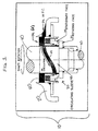
- FIG. 1 illustrates a vertical pump gear box seal 10 with oil (or cooling fluid) A at the ID.
- a housing 20 encloses a mechanical seal 30 disposed about a vertically oriented shaft 40. The seal has two faces - a stationary face 32, coupled to the housing 20, and a rotating face 34, coupled to the shaft 40.
- the housing 20 also encloses a fluid chamber 50, which contains the cooling fluid A supplied through inlet 52 from a reservoir (not shown).
- the fluid chamber 50 surrounds the shaft, and provides fluid to the faces of the seal.
- a sleeve 42 is coupled concentrically about the shaft, and the outer surface of the sleeve 42 defines a closed loop fluid path 44.
- the closed loop path is a groove having a base 43 and two spaced apart walls 45 (See FIG. 2).
- the closed loop fluid path 44 is preferably a continuous groove about the sleeve, most preferably sinusoidal in circumferential profile and spanning substantially the axial dimension of the chamber 50.
- the high point of the closed loop 44 is near the high point of the chamber 50, while the low point of the closed loop 44 is near the low point of the chamber 50.
- the circumferential profile of the closed loop can be a variety of shapes, that preferably substantially spans the axial dimension of the chamber 50.
- the sinusoidal design offers excellent cooling performance due to the minimization of turbulence in the oil. Turbulence is reduced because the entrance point (upper right of sleeve in FIG. 1) and the return point (lower left of sleeve in FIG. 1) are tangential to the direction of motion which results in a smooth transition for change in flow direction. Reducing turbulence increases cooling.
- the outer surface of the shaft 40 can define the closed loop fluid path 44.
- the closed loop fluid path 44 rotates also. Because the closed loop fluid path substantially spans the axial dimension of the chamber, it appears to move up and down. Viewing the sleeve from a fixed viewpoint, as the shaft rotates the closed loop fluid path appears to oscillate up and down in a sinusoidal fashion. This axial movement takes the cooling liquid from the top of the chamber and "pumps" it down to the face of the seal at the bottom of the chamber, then lifts the heated fluid away from the seal at the bottom of the chamber and brings it to the top. In other words, when oil engages the entrance point in the sleeve groove, it is pumped to the left, because of shaft rotation, as shown by the oil circulation arrow.
- FIG. 3 illustrates another embodiment of the invention, where the shaft 40 is horizontally oriented in a tandem seal or double seal arrangement.
- a housing 20 encloses two mechanical seals - a primary seal 30 and a secondary seal 31 - disposed about a horizontally oriented shaft 40. Each seal has two faces - a stationary face 32,33 coupled to the housing 20, and a rotating face 34,35 coupled to the shaft 40.
- the housing 20 also encloses a fluid chamber 50, which contains the cooling fluid.
- the fluid chamber 50 surrounds the shaft, and provides fluid to the faces of the seals.
- the chamber encloses an area about the shaft from the inner diameter of the primary seal 30, extending along the shaft to the outer diameter of the secondary seal 31.
- the orientation of the seals may be varied without departing from the present invention.
- the chamber extends from the outer diameter of the primary seal to the inner diameter of the secondary seal.
- the chamber extends along the shaft from the inner diameter of the primary seal to the inner diameter of the secondary seal.
- a sleeve 42 is coupled concentrically about the shaft, and the outer surface of the sleeve 42 defines a closed loop fluid path 44.
- the closed loop fluid path 44 is a continuous groove about the sleeve, preferably sinusoidal in circumferential profile.
- the closed loop fluid path 44 is located partially within the chamber portion containing the primary seal. Distal from this position, and located axially along the shaft at substantially the location of the secondary seal, are the inlet 52 and outlet 54 which communicate with the cooling fluid reservoir (not shown).
- the pumping action of the closed loop fluid path 44 draws cooling fluid from the inlet, circulates the fluid through the chamber, and expels the fluid to the fluid reservoir through the outlet 54.
- the inlet and outlet are offset radially about the shaft from one another, but are located at substantially the same axial position. However, it will be appreciated by those skilled in the art that the inlet 52 and outlet 54 may be located at other locations.
- the cooling assembly may be used with a single mechanical seal, as well as in a tandem or double-seal configuration, or configurations utilizing more than two mechanical seals.
- FIG. 4 illustrates a linear groove design 80 having an angular shape.
- the sinusoidal groove offers significant cooling over both.
Landscapes
- Engineering & Computer Science (AREA)
- General Engineering & Computer Science (AREA)
- Mechanical Engineering (AREA)
- Mechanical Sealing (AREA)
Claims (6)
- Mechanische Dichtungsanordnung, umfassend:dadurch gekennzeichnet, dass der Fluidweg (44) ein geschlossener Kreisweg um die Welle (40) ist zur Zirkulation von Fluid zu und von den Dichtungsoberflächen.eine drehbare Welle (40);eine mechanische Dichtung (30), die um die Welle (40) herum angeordnet ist, wobei die Dichtung eine mit der Welle (40) verbundene drehbare Oberfläche (34) und eine unbewegliche Oberfläche (32) hat, wobei die jeweiligen Oberflächen in entgegengesetzter Beziehung zueinander sind, um eine Dichtung zu bilden;eine Kammer (50) zum Enthalten eines Kühlungsfluids, wobei die Kammer um die Welle (40) herum angeordnet ist und mit den Oberflächen der Dichtung (30) in Verbindung steht; undeinen Fluidweg (44), der um die Außenfläche der Welle herum angeordnet ist und sowohl axial als auch in Umfangsrichtung in Fluidverbindung mit der Kammer stehend verläuft,
- Dichtungsanordnung nach Anspruch 1, ferner umfassend eine Hülse (42), die mit einem Teil der Welle verbunden und konzentrisch um ihn herum angeordnet ist, wobei der geschlossene Fluidkreisweg (44) an der Außenfläche der Hülse angeordnet ist.
- Dichtungsanordnung nach Anspruch 2, bei der der geschlossene Fluidkreisweg (44) von zwei voneinander beabstandeten Wandflächen (45) definiert wird, die radial senkrecht von der Hülse vorspringen.
- Dichtungsanordnung nach Anspruch 2, bei der der geschlossene Fluidkreisweg von einer Rille in der Hülse gebildet wird.
- Dichtungsanordnung nach einem der vorhergehenden Ansprüche, bei der der geschlossene Kreisweg im Umfangsprofil sinusförmig ist.
- Dichtungsanordnung nach einem der vorhergehenden Ansprüche, bei der der geschlossene Fluidkreisweg zum Innendurchmesser der Dichtungsflächen verläuft.
Applications Claiming Priority (3)
| Application Number | Priority Date | Filing Date | Title |
|---|---|---|---|
| US384312 | 1999-08-26 | ||
| US09/384,312 US6296254B1 (en) | 1999-08-26 | 1999-08-26 | Mechanical seal assembly with improved fluid circulation |
| PCT/US1999/023836 WO2001014769A1 (en) | 1999-08-26 | 1999-10-14 | Mechanical seal assembly with improved fluid circulation |
Publications (2)
| Publication Number | Publication Date |
|---|---|
| EP1210535A1 EP1210535A1 (de) | 2002-06-05 |
| EP1210535B1 true EP1210535B1 (de) | 2005-02-02 |
Family
ID=23516829
Family Applications (1)
| Application Number | Title | Priority Date | Filing Date |
|---|---|---|---|
| EP99951969A Expired - Lifetime EP1210535B1 (de) | 1999-08-26 | 1999-10-14 | Gleitringdichtungsanordnung mit verbessertem flüssigkeitsumlauf |
Country Status (6)
| Country | Link |
|---|---|
| US (1) | US6296254B1 (de) |
| EP (1) | EP1210535B1 (de) |
| AU (1) | AU762551B2 (de) |
| CA (1) | CA2383216C (de) |
| DE (1) | DE69923609T2 (de) |
| WO (1) | WO2001014769A1 (de) |
Families Citing this family (9)
| Publication number | Priority date | Publication date | Assignee | Title |
|---|---|---|---|---|
| US20020181325A1 (en) * | 2001-06-05 | 2002-12-05 | Engel David J | Mixer seal and bearing apparatus and method |
| US6854955B2 (en) | 2003-01-07 | 2005-02-15 | Sundyne Corporation | Internal lubrication screw pump for hollow shaft |
| SE531613C2 (sv) * | 2005-06-27 | 2009-06-09 | Huhnseal Ab | Tätningsanordning |
| US20080111314A1 (en) * | 2006-11-09 | 2008-05-15 | Cheng-Shiou Huang | Shaft sealing assembly with liquid stirring unit |
| US10077403B2 (en) * | 2009-05-04 | 2018-09-18 | Flowserve Management Company | Nozzles for a fluid jet decoking tool |
| US8584695B2 (en) | 2010-10-15 | 2013-11-19 | Ideal Time Consultants Limited | Air valve for inflatable device |
| JP6386814B2 (ja) * | 2013-07-03 | 2018-09-05 | Ntn株式会社 | シールリング |
| JP2016540898A (ja) * | 2013-10-17 | 2016-12-28 | ジーケーエヌ シンター メタルズ、エル・エル・シー | 径方向に延びる間隔を空けた開口を有する焼結金属部品とその製造方法 |
| DE102014009790A1 (de) * | 2014-06-27 | 2015-12-31 | Kaco Gmbh + Co. Kg | Dichtungsanordnung |
Family Cites Families (20)
| Publication number | Priority date | Publication date | Assignee | Title |
|---|---|---|---|---|
| US2802679A (en) * | 1953-06-30 | 1957-08-13 | Nat Lead Co | Mechanical seal for pumps |
| US2992842A (en) | 1958-04-21 | 1961-07-18 | United Aircraft Corp | Oil scrubbed face seal |
| US3068012A (en) | 1959-10-08 | 1962-12-11 | Chesterton A W Co | Mechanical seal |
| US3889960A (en) | 1972-10-04 | 1975-06-17 | Borg Warner | Cooling seal |
| US3806135A (en) | 1972-10-04 | 1974-04-23 | Borg Warner | Cooling seal |
| US3937477A (en) | 1973-12-26 | 1976-02-10 | Borg-Warner Corporation | Mechanical seal system |
| US4243230A (en) | 1979-10-01 | 1981-01-06 | Crane Packing Co. | Low energy tandem seal |
| US4466619A (en) | 1981-07-13 | 1984-08-21 | Durametallic Corporation | Mechanical seal assembly with integral pumping device |
| US4445695A (en) | 1982-03-10 | 1984-05-01 | Crane Packing Limited | Rotary mechanical seals |
| US4560173A (en) | 1984-06-01 | 1985-12-24 | Durametallic Corporation | Mechanical seal assembly with coolant circulation structure |
| US4759553A (en) | 1986-01-27 | 1988-07-26 | The Fluorocarbon Company | Dynamic rotary face seal |
| US4699575A (en) * | 1986-02-12 | 1987-10-13 | Robotics, Inc. | Adhesive pump and it's control system |
| DD289875A7 (de) * | 1988-10-28 | 1991-05-16 | Petrolchemie U. Kraftstoff Ag Schwedt,De | Permanente schneckenlager-oelschmierung an dekantierzentrifugen |
| US5217234A (en) * | 1991-03-22 | 1993-06-08 | John Hornsby | Mechanical seal with barrier fluid circulation system |
| WO1995035457A1 (en) * | 1994-06-20 | 1995-12-28 | Ramsay Thomas W | Seal/bearing assembly |
| JP3405994B2 (ja) * | 1995-10-02 | 2003-05-12 | エイ・ダブリユ・チエスタートン・カンパニー | ロータリシールおよび/またはベアリング |
| DE29602685U1 (de) | 1996-02-15 | 1996-04-11 | Feodor Burgmann Dichtungswerke GmbH & Co, 82515 Wolfratshausen | Gleitringdichtungsanordnung |
| US5847479A (en) * | 1997-04-15 | 1998-12-08 | Sae Magnetics (H.K.) Ltd. | Self-pressure-balanced hydrodynamic bearing spindle motor |
| DE29713603U1 (de) | 1997-07-31 | 1997-10-02 | Depac Dichtungstechnik Gmbh, Bludenz | Doppelgleitringdichtung |
| US5938205A (en) * | 1997-08-18 | 1999-08-17 | A.W. Chesterton Company | Method and apparatus for optimizing barrier fluid flow for promoting cool running of a cartridge dual seal |
-
1999
- 1999-08-26 US US09/384,312 patent/US6296254B1/en not_active Expired - Lifetime
- 1999-10-14 CA CA002383216A patent/CA2383216C/en not_active Expired - Lifetime
- 1999-10-14 DE DE69923609T patent/DE69923609T2/de not_active Expired - Lifetime
- 1999-10-14 AU AU64290/99A patent/AU762551B2/en not_active Expired
- 1999-10-14 EP EP99951969A patent/EP1210535B1/de not_active Expired - Lifetime
- 1999-10-14 WO PCT/US1999/023836 patent/WO2001014769A1/en not_active Ceased
Also Published As
| Publication number | Publication date |
|---|---|
| DE69923609D1 (de) | 2005-03-10 |
| WO2001014769A1 (en) | 2001-03-01 |
| CA2383216C (en) | 2008-12-30 |
| AU762551B2 (en) | 2003-06-26 |
| US6296254B1 (en) | 2001-10-02 |
| EP1210535A1 (de) | 2002-06-05 |
| AU6429099A (en) | 2001-03-19 |
| CA2383216A1 (en) | 2001-03-01 |
| DE69923609T2 (de) | 2006-03-30 |
Similar Documents
| Publication | Publication Date | Title |
|---|---|---|
| US3947153A (en) | Lubricated thrust bearings for pump and motor units | |
| EP1210535B1 (de) | Gleitringdichtungsanordnung mit verbessertem flüssigkeitsumlauf | |
| EP0235505A2 (de) | Kühlvorrichtung für die Lager einer Heizrolle | |
| CA3062990A1 (en) | A bearing housing for a flow machine and a flow machine with a bearing housing | |
| JP2009287413A (ja) | スクリュ流体機械 | |
| EP2662572A1 (de) | Abdichtungsanordnung für den Schmierstoff eines Kugellagers in einer Strömungsmaschine | |
| US4936742A (en) | Water pump apparatus having lubricating oil circulation and axial thrust support | |
| EP0283292B1 (de) | Pumpe mit Wärmeaustauscher | |
| KR102377227B1 (ko) | 백투백 베어링 밀봉 시스템 | |
| EP1111287A1 (de) | Drehverbindung für den Hochtemperatureinsatz | |
| KR100681477B1 (ko) | 배출장치 | |
| US20250003417A1 (en) | Centrifugal Pump Having a Cooling Insert | |
| JP5524778B2 (ja) | 立型軸受装置 | |
| AU2013387156A1 (en) | Vane-type rotary vacuum pump | |
| KR102427489B1 (ko) | 누유 방지 구조를 구비한 수직형 베어링 | |
| EP0280778A2 (de) | Kühlung für eine Dichtungsvorrichtung | |
| JPH07259752A (ja) | 歯車ポンプロータの軸を冷却する方法・歯車ポンプロータ及び歯車ポンプ | |
| CN116624400B (zh) | 一种温控机用热媒泵 | |
| US5863133A (en) | Vertical bearing assembly lubrication | |
| US20040070152A1 (en) | Ventilated pump shaft seal | |
| CN223908463U (zh) | 机械密封机构、冷却密封装置及设备 | |
| US12313158B1 (en) | Lubricating mechanism for planetary gear train | |
| JPH0126930Y2 (de) | ||
| EP4242484A1 (de) | Lagerring für eine rotierende elektrische maschine und entsprechende rotierende elektrische maschine | |
| JP2542995Y2 (ja) | キャンドモータホンプの軸受支持装置 |
Legal Events
| Date | Code | Title | Description |
|---|---|---|---|
| PUAI | Public reference made under article 153(3) epc to a published international application that has entered the european phase |
Free format text: ORIGINAL CODE: 0009012 |
|
| AK | Designated contracting states |
Kind code of ref document: A1 Designated state(s): AT BE CH CY DE DK ES FI FR GB GR IE IT LI LU MC NL PT SE |
|
| 17P | Request for examination filed |
Effective date: 20020318 |
|
| 17Q | First examination report despatched |
Effective date: 20031219 |
|
| RBV | Designated contracting states (corrected) |
Designated state(s): DE FR GB NL |
|
| GRAP | Despatch of communication of intention to grant a patent |
Free format text: ORIGINAL CODE: EPIDOSNIGR1 |
|
| GRAA | (expected) grant |
Free format text: ORIGINAL CODE: 0009210 |
|
| GRAS | Grant fee paid |
Free format text: ORIGINAL CODE: EPIDOSNIGR3 |
|
| AK | Designated contracting states |
Kind code of ref document: B1 Designated state(s): DE FR GB NL |
|
| REG | Reference to a national code |
Ref country code: GB Ref legal event code: FG4D |
|
| REG | Reference to a national code |
Ref country code: IE Ref legal event code: FG4D |
|
| REF | Corresponds to: |
Ref document number: 69923609 Country of ref document: DE Date of ref document: 20050310 Kind code of ref document: P |
|
| PGFP | Annual fee paid to national office [announced via postgrant information from national office to epo] |
Ref country code: NL Payment date: 20051003 Year of fee payment: 7 |
|
| PGFP | Annual fee paid to national office [announced via postgrant information from national office to epo] |
Ref country code: FR Payment date: 20051010 Year of fee payment: 7 |
|
| PLBE | No opposition filed within time limit |
Free format text: ORIGINAL CODE: 0009261 |
|
| STAA | Information on the status of an ep patent application or granted ep patent |
Free format text: STATUS: NO OPPOSITION FILED WITHIN TIME LIMIT |
|
| 26N | No opposition filed |
Effective date: 20051103 |
|
| ET | Fr: translation filed | ||
| PG25 | Lapsed in a contracting state [announced via postgrant information from national office to epo] |
Ref country code: NL Free format text: LAPSE BECAUSE OF NON-PAYMENT OF DUE FEES Effective date: 20070501 |
|
| NLV4 | Nl: lapsed or anulled due to non-payment of the annual fee |
Effective date: 20070501 |
|
| REG | Reference to a national code |
Ref country code: FR Ref legal event code: ST Effective date: 20070629 |
|
| PG25 | Lapsed in a contracting state [announced via postgrant information from national office to epo] |
Ref country code: FR Free format text: LAPSE BECAUSE OF NON-PAYMENT OF DUE FEES Effective date: 20061031 |
|
| PGFP | Annual fee paid to national office [announced via postgrant information from national office to epo] |
Ref country code: DE Payment date: 20181029 Year of fee payment: 20 |
|
| PGFP | Annual fee paid to national office [announced via postgrant information from national office to epo] |
Ref country code: GB Payment date: 20181029 Year of fee payment: 20 |
|
| REG | Reference to a national code |
Ref country code: DE Ref legal event code: R071 Ref document number: 69923609 Country of ref document: DE |
|
| REG | Reference to a national code |
Ref country code: GB Ref legal event code: PE20 Expiry date: 20191013 |
|
| PG25 | Lapsed in a contracting state [announced via postgrant information from national office to epo] |
Ref country code: GB Free format text: LAPSE BECAUSE OF EXPIRATION OF PROTECTION Effective date: 20191013 |