EP1210568B1 - Verformungskörper - Google Patents
Verformungskörper Download PDFInfo
- Publication number
- EP1210568B1 EP1210568B1 EP99944614A EP99944614A EP1210568B1 EP 1210568 B1 EP1210568 B1 EP 1210568B1 EP 99944614 A EP99944614 A EP 99944614A EP 99944614 A EP99944614 A EP 99944614A EP 1210568 B1 EP1210568 B1 EP 1210568B1
- Authority
- EP
- European Patent Office
- Prior art keywords
- diameter
- recess
- distance
- section
- body section
- Prior art date
- Legal status (The legal status is an assumption and is not a legal conclusion. Google has not performed a legal analysis and makes no representation as to the accuracy of the status listed.)
- Expired - Lifetime
Links
- 230000035945 sensitivity Effects 0.000 description 5
- 238000005259 measurement Methods 0.000 description 4
- 230000000694 effects Effects 0.000 description 3
- 239000000463 material Substances 0.000 description 3
- 238000000034 method Methods 0.000 description 3
- 229910001006 Constantan Inorganic materials 0.000 description 2
- 229910000831 Steel Inorganic materials 0.000 description 2
- BASFCYQUMIYNBI-UHFFFAOYSA-N platinum Chemical compound [Pt] BASFCYQUMIYNBI-UHFFFAOYSA-N 0.000 description 2
- 239000004065 semiconductor Substances 0.000 description 2
- 239000010959 steel Substances 0.000 description 2
- 238000005452 bending Methods 0.000 description 1
- 230000000977 initiatory effect Effects 0.000 description 1
- 238000009434 installation Methods 0.000 description 1
- 238000004519 manufacturing process Methods 0.000 description 1
- 239000007769 metal material Substances 0.000 description 1
- 229910052697 platinum Inorganic materials 0.000 description 1
- 238000005303 weighing Methods 0.000 description 1
Images
Classifications
-
- G—PHYSICS
- G01—MEASURING; TESTING
- G01G—WEIGHING
- G01G3/00—Weighing apparatus characterised by the use of elastically-deformable members, e.g. spring balances
- G01G3/12—Weighing apparatus characterised by the use of elastically-deformable members, e.g. spring balances wherein the weighing element is in the form of a solid body stressed by pressure or tension during weighing
- G01G3/14—Weighing apparatus characterised by the use of elastically-deformable members, e.g. spring balances wherein the weighing element is in the form of a solid body stressed by pressure or tension during weighing measuring variations of electrical resistance
- G01G3/1402—Special supports with preselected places to mount the resistance strain gauges; Mounting of supports
- G01G3/1408—Special supports with preselected places to mount the resistance strain gauges; Mounting of supports the supports being of the column type, e.g. cylindric
-
- G—PHYSICS
- G01—MEASURING; TESTING
- G01L—MEASURING FORCE, STRESS, TORQUE, WORK, MECHANICAL POWER, MECHANICAL EFFICIENCY, OR FLUID PRESSURE
- G01L1/00—Measuring force or stress, in general
- G01L1/20—Measuring force or stress, in general by measuring variations in ohmic resistance of solid materials or of electrically-conductive fluids; by making use of electrokinetic cells, i.e. liquid-containing cells wherein an electrical potential is produced or varied upon the application of stress
- G01L1/22—Measuring force or stress, in general by measuring variations in ohmic resistance of solid materials or of electrically-conductive fluids; by making use of electrokinetic cells, i.e. liquid-containing cells wherein an electrical potential is produced or varied upon the application of stress using resistance strain gauges
- G01L1/2206—Special supports with preselected places to mount the resistance strain gauges; Mounting of supports
- G01L1/2218—Special supports with preselected places to mount the resistance strain gauges; Mounting of supports the supports being of the column type, e.g. cylindric, adapted for measuring a force along a single direction
Definitions
- the invention relates to a deformation body for Use in a load cell with one head and one torso and a foot with the top end face of the head in is essentially designed as a spherical surface, the head from the fuselage by at least one upper puncture the fuselage is essentially cylindrical is formed in the fuselage on an axis perpendicular to Longitudinal axis of the deformation body two one depth less than the radius of the fuselage Cross holes are provided through the foot from the fuselage at least one lower puncture is made and the lower end surface of the foot essentially as Spherical surface is formed.
- Deformation bodies with such a geometry are for different load levels since about the mid-eighties Years known and are mainly in Pressure load cells but also in train load cells used.
- the decisive factor is with the deformation bodies the choice of dimensions for a given Geometry, so that a load measurement is guaranteed in terms of their linearity and hysteresis without additional measures, such as installation of semiconductor strain gauges, accuracy classes of 0.010% and better met.
- the use of Strain gauge is special problematic in that this is significant Have quality problems.
- Deformation bodies for use in load cells consist of a high-strength metallic material, usually made of Steel. On the surface of this deformation body are strain gauges at a suitable point, in usually constantan or platinum strain gauges, arranged. These strain gauges are common electrically connected as a Wheatstone full bridge.
- the Sensitivity of the load cell in the one above Deformation body described is used in mV / V specified. This is the one on the full bridge applied signal voltage per volt supply voltage at Understand the nominal load. This information depends on the Type of strain gauge used or the k factor of the strain gauge. In the further Description is always from the use of Constantan strain gauges based on a k factor of about 2.
- Deformation body e.g. Cylinders
- more or less large linearity errors when in their longitudinal axis be loaded by pressure or tension That is why you are not suitable, used in legal-for-trade weighing systems to be if their measurement errors do not have additional measures be reduced.
- a compensation by means of Semiconductor strain gauges for linearization known among other methods, a compensation by means of Semiconductor strain gauges.
- the present invention has for its object a Deformation body for use in a load cell for To provide, which at a nominal load of about 50 t highest demands on linearity and Deformation hysteresis met.
- the diameter of the upper groove is 38 mm ⁇ 10 mm
- the Diameter of the fuselage is 72 mm ⁇ 10 mm
- the Distance of the transverse hole axis from the upper recess ⁇ 10 mm dem Distance of the cross hole axis from the lower recess corresponds to, the diameter of the transverse holes 24 mm -5 mm / + 10 mm
- the distance between the end faces of the Cross holes from each other is 28 mm ⁇ 10 mm
- the distance of the upper groove from the lower groove 61 mm ⁇ 20 mm is and the diameter of the lower recess 40 mm ⁇ Is 10 mm.
- a deformation body with the specified preferred dimensions delivers an output signal of for a nominal load of 50 t 2 mV / V with a verifiable characteristic, i.e. with very good linearity and low hysteresis.
- Deformation body, the geometrical dimensions of which Preferred dimensions differ within the specified limits also meet high linearity requirements or the hysteresis. Even minor ones Deviations in a geometric dimension opposing, minor deviations in one compensate for another geometric dimension without this on Linearity and hysteresis have significant effects. It is quite conceivable from a price-performance point of view high tolerances within the specified limits, for the geometric dimensions permit.
- the radius of the upper end surface is 35 mm -10 mm / + 500 mm, it is guaranteed that light Angular errors in the load introduction points compensated and the actual deformation geometry do not place unnecessary stresses on a bending moment.
- the radius of the lower End area is 220 mm -100 mm / + 500 mm. It's from Advantage of increasing the radius of the lower end face choose to ensure that the stability behavior and shear force and torque influences work well together are coordinated.
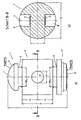
- Embodiment of an inventive Deformation body for use in a load cell has a head 1, a torso 2 and a foot 3.
- the upper end surface 4 of the head 3 is essentially as Spherical surface formed.
- the head 1 is through from the fuselage 2 an upper puncture 5 removed.
- In the main cylindrical hull 2 are on one axis 6 perpendicular to the longitudinal axis 7 of the deformation body two a depth less than the radius of the fuselage 2 having transverse holes 8 provided.
- the foot 3 is from Hull 2 as well as head 1 by a lower one Puncture 9 discontinued.
- the bottom one End surface 10 of the foot 3 essentially as a spherical surface educated.
- the diameter of the upper recess (5) (D o ) is 38 mm
- the diameter of the fuselage (2) (D) 72 mm the diameter of the transverse holes (8) (d) 24 mm, the distance between the end faces (s) 28 mm from each other, the distance of the upper recess (5) from the lower recess (9) (A) 61 mm and the diameter of the lower recess (9) (D U ) 40 mm.
- the distance of the transverse hole axis 6 from the upper recess 5 (h o ) preferably corresponds exactly to the distance of the lower recess 9 (h U ) from the transverse hole axis 6.
- the radius R K of the upper end face 4 is 35 mm, while the radius R F of the lower end face 10 of the foot 3 is 220 mm.
- the length L of the deformation body is 118.5 mm in the illustrated embodiment.
- Strain gauges 11 provided for recording measured values are in the described deformation bodies on both Bottoms of the transverse holes 8 arranged, whereby the Linearity and hysteresis requirements met can be.
- the punctures 5, 9 are necessary in some form. Their diameter is about half Outer diameter of the fuselage 2. Your minimum diameter but is due to the required strength for the the intended maximum load is limited. Both punctures 5, 9 serve for the targeted introduction of load into the fuselage 2. Above the upper recess 5 and below the lower groove 9 should still have some material remain so that the voltage peaks of the Load initiation, which is close to the interfaces result from the load, if possible still within the Protrusions over the punctures 5, 9 to an uncritical Can reduce dimension. The mainly for the Measurement properties and thus also for sensitivity the decisive geometry is given by the recesses 5, 9 limits and forms the so-called deformation geometry.
- the on the punctures 5, 9 is the so-called outer geometry not insignificant, but plays a subordinate one Roll, so that a deviation of 1 mm within the Deformation geometry has a greater impact on the Quality of the measurement signal has a deviation of 1 mm in the outer geometry.
- the Total length L with the outer geometry therefore has one less influence and can therefore be adapt to external circumstances.
- the embodiment described in connection with the drawing has a sensitivity of 1 mV / V at a nominal load of 25,000 kg and 2 mV / V at a nominal load of using a strain gauge full bridge whose strain gauge has a k-factor of about 2 50,000 kg.
- the elastic modulus of the material in the illustrated embodiment steel, is 200,000 N / mm 2 ⁇ 15,000 N / mm 2 .
- the calibration of sensitivity is also on everyone other intermediate value possible, so also - if desired - due to slight geometry adjustment to that for Force transducer decisive SI unit Newton. at Using one material with another The modulus of elasticity is also directly proportional another sensitivity.
Landscapes
- Physics & Mathematics (AREA)
- General Physics & Mathematics (AREA)
- Measurement Of Force In General (AREA)
Description
Claims (3)
- Verformungskörper zum Einsatz in einer Wägezelle mit einem Kopf (1), einem Rumpf (2) und einem Fuß (3), wobei die obere Endfläche (4) des Kopfes (1) im wesentlichen als Kugelfläche ausgebildet ist, der Kopf (1) vom Rumpf (2) durch mindestens einen oberen Einstich (5) abgesetzt ist, der Rumpf (2) im wesentlichen zylinderförmig ausgebildet ist, im Rumpf (2) auf einer Achse (6) senkrecht zur Längsachse (7) des Verformungskörpers zwei eine Tiefe geringer als der Radius des Rumpfes (2) aufweisende Querlöcher (8) vorgesehen sind, der Fuß (3) vom Rumpf (2) durch mindestens einen unteren Einstich (9) abgesetzt ist und die untere Endfläche (10) des Fußes (3) im wesentlichen als Kugelfläche ausgebildet ist,
dadurch gekennzeichnet, daß der Durchmesser (Do) des oberen Einstichs (5) 38 mm ± 10 mm beträgt, der Durchmesser (D) des Rumpfes (2) 72 mm ± 10 mm beträgt, der Abstand (ho) der Querlochachse (6) vom oberen Einstich (5) ± 10 mm dem Abstand (hu) der Querlochachse vom unteren Einstich (9) entspricht, der Durchmesser (d) der Querlöcher (8) 24 mm -5 mm/+10 mm beträgt, der Abstand (s) der Endflächen der Querlöcher (8) voneinander 28 mm ± 10 mm beträgt, der Abstand (A) des oberen Einstichs (5) vom unteren Einstich (9) 61 mm ± 20 mm beträgt und der Durchmesser (Du) des unteren Einstichs (9) 40 mm ± 10 mm beträgt. - Verformungskörper nach Anspruch 1,
dadurch gekennzeichnet, daß der Radius der oberen Endfläche (4) 35 mm -10 mm/+500 mm beträgt. - Verformungskörper nach Anspruch 1 oder 2,
dadurch gekennzeichnet, daß der Radius der unteren Endfläche (10) 220 mm -100 mm/+500 mm beträgt.
Applications Claiming Priority (1)
| Application Number | Priority Date | Filing Date | Title |
|---|---|---|---|
| PCT/EP1999/006558 WO2001018504A1 (de) | 1999-09-07 | 1999-09-07 | Verformungskörper |
Publications (2)
| Publication Number | Publication Date |
|---|---|
| EP1210568A1 EP1210568A1 (de) | 2002-06-05 |
| EP1210568B1 true EP1210568B1 (de) | 2004-01-14 |
Family
ID=8167427
Family Applications (1)
| Application Number | Title | Priority Date | Filing Date |
|---|---|---|---|
| EP99944614A Expired - Lifetime EP1210568B1 (de) | 1999-09-07 | 1999-09-07 | Verformungskörper |
Country Status (4)
| Country | Link |
|---|---|
| EP (1) | EP1210568B1 (de) |
| AU (1) | AU5745999A (de) |
| DE (1) | DE59908327D1 (de) |
| WO (1) | WO2001018504A1 (de) |
Families Citing this family (3)
| Publication number | Priority date | Publication date | Assignee | Title |
|---|---|---|---|---|
| DE10341482B4 (de) * | 2003-09-05 | 2005-07-21 | Sartorius Hamburg Gmbh | Gehäuselose Wägezelle |
| DE102013012506A1 (de) | 2013-07-26 | 2015-01-29 | Hottinger Baldwin Messtechnik Gmbh | Stabförmiger Kraftaufnehmer mit verbessertem Verformungsverhalten |
| DE102013012507B4 (de) | 2013-07-26 | 2016-06-16 | Hottinger Baldwin Messtechnik Gmbh | Stabförmiger Kraftaufnehmer mit vereinfachtem Abgleich |
Family Cites Families (3)
| Publication number | Priority date | Publication date | Assignee | Title |
|---|---|---|---|---|
| DE3405127A1 (de) * | 1984-02-14 | 1985-09-05 | Philips Patentverwaltung Gmbh, 2000 Hamburg | Kraftaufnehmer |
| US4733571A (en) * | 1986-10-24 | 1988-03-29 | Ormond Alfred N | Linearization of column-type load cell |
| IT1287416B1 (it) * | 1996-04-01 | 1998-08-06 | Cooperativa Bilanciai Campogal | Trasduttore di forza a colonna |
-
1999
- 1999-09-07 AU AU57459/99A patent/AU5745999A/en not_active Abandoned
- 1999-09-07 WO PCT/EP1999/006558 patent/WO2001018504A1/de not_active Ceased
- 1999-09-07 DE DE59908327T patent/DE59908327D1/de not_active Expired - Lifetime
- 1999-09-07 EP EP99944614A patent/EP1210568B1/de not_active Expired - Lifetime
Also Published As
| Publication number | Publication date |
|---|---|
| WO2001018504A1 (de) | 2001-03-15 |
| AU5745999A (en) | 2001-04-10 |
| DE59908327D1 (de) | 2004-02-19 |
| EP1210568A1 (de) | 2002-06-05 |
Similar Documents
| Publication | Publication Date | Title |
|---|---|---|
| EP3239676A1 (de) | Kraftmesssensor | |
| EP1719992B1 (de) | Linearwälzlager mit am Führungswagen angebrachtem Dehnungsmessstreifen | |
| DE69005370T2 (de) | Membranmessfühler mit Konzentration von Deformationen. | |
| DE3218577A1 (de) | Kraftwandler | |
| EP1210568B1 (de) | Verformungskörper | |
| DE2631698C2 (de) | Kraftmeßwandler | |
| DE2124112A1 (de) | Hohlzylindrischer Meßgrößenumformer mit Beanspru chungsmeßeinrichtungen | |
| EP0310758A2 (de) | Elektromechanische Waage | |
| DE2207852A1 (de) | Piezoelektrisches Kristallelement | |
| DE2758997C2 (de) | Meßglied zum Messen des Raddruckes des Rades eines Schienenfahrzeuges | |
| DE3148403A1 (de) | "differenzdruckmesser" | |
| EP1194753A1 (de) | Kraftmesselement für eine waage | |
| DE3873901T3 (de) | Vorrichtung zur Messung des Gewichts. | |
| DE10260577B4 (de) | Dehnungsmessstreifen mit veränderbarem Nennwiderstand | |
| DE2215620B2 (de) | Einrichtung zur Ermittlung der Belastung eines Trägers, einer Stütze oder dgl. mittels Kraftmeßdosen | |
| DE2904844B2 (de) | Druckmeßeinrichtung zur Messung und Überwachung von Betonspannungen | |
| DE3512969C2 (de) | ||
| DE4142141A1 (de) | Kraftmesseinrichtung | |
| DE2414569C2 (de) | KraftmeBgerät zum Messen von kleinen Kräften, insbesondere von Kontaktfederkräften sowie Verfahren zur Herstellung eines derartigen Gerätes | |
| EP1931935A1 (de) | Kalibrierlehre zur kalibrierung eines messschiebers | |
| DE1932224B2 (de) | Elektromechanischer Kraft-Meßwandler | |
| DE1924106A1 (de) | Dreikomponenten-Kraftmessdose | |
| EP2402730A1 (de) | Kraftaufnehmer mit Biegebalken mit kontinuierlicher Verjüngung | |
| DE1427796A1 (de) | Anordnung zum Messen des Walzdruckes in Walzenstuehlen | |
| DE4243807C2 (de) | Vorrichtung zur Prüfung der Ebenheit und der Lage eines Deckelstabes für eine Karde |
Legal Events
| Date | Code | Title | Description |
|---|---|---|---|
| PUAI | Public reference made under article 153(3) epc to a published international application that has entered the european phase |
Free format text: ORIGINAL CODE: 0009012 |
|
| 17P | Request for examination filed |
Effective date: 20020228 |
|
| AK | Designated contracting states |
Kind code of ref document: A1 Designated state(s): AT BE CH CY DE DK ES FI FR GB GR IE IT LI LU MC NL PT SE |
|
| GRAP | Despatch of communication of intention to grant a patent |
Free format text: ORIGINAL CODE: EPIDOSNIGR1 |
|
| GRAS | Grant fee paid |
Free format text: ORIGINAL CODE: EPIDOSNIGR3 |
|
| GRAA | (expected) grant |
Free format text: ORIGINAL CODE: 0009210 |
|
| AK | Designated contracting states |
Kind code of ref document: B1 Designated state(s): DE FR GB IT NL |
|
| REG | Reference to a national code |
Ref country code: GB Ref legal event code: FG4D Free format text: NOT ENGLISH |
|
| REG | Reference to a national code |
Ref country code: IE Ref legal event code: FG4D Free format text: GERMAN |
|
| REF | Corresponds to: |
Ref document number: 59908327 Country of ref document: DE Date of ref document: 20040219 Kind code of ref document: P |
|
| GBT | Gb: translation of ep patent filed (gb section 77(6)(a)/1977) |
Effective date: 20040401 |
|
| REG | Reference to a national code |
Ref country code: IE Ref legal event code: FD4D |
|
| ET | Fr: translation filed | ||
| PLBE | No opposition filed within time limit |
Free format text: ORIGINAL CODE: 0009261 |
|
| STAA | Information on the status of an ep patent application or granted ep patent |
Free format text: STATUS: NO OPPOSITION FILED WITHIN TIME LIMIT |
|
| 26N | No opposition filed |
Effective date: 20041015 |
|
| REG | Reference to a national code |
Ref country code: NL Ref legal event code: TD Effective date: 20110304 |
|
| REG | Reference to a national code |
Ref country code: DE Ref legal event code: R081 Ref document number: 59908327 Country of ref document: DE Owner name: MINEBEA INTEC GMBH, DE Free format text: FORMER OWNER: SARTORIUS HAMBURG GMBH, 22145 HAMBURG, DE Effective date: 20110228 Ref country code: DE Ref legal event code: R081 Ref document number: 59908327 Country of ref document: DE Owner name: SARTORIUS MECHATRONICS T&H GMBH, DE Free format text: FORMER OWNER: SARTORIUS HAMBURG GMBH, 22145 HAMBURG, DE Effective date: 20110228 |
|
| REG | Reference to a national code |
Ref country code: FR Ref legal event code: CD |
|
| REG | Reference to a national code |
Ref country code: DE Ref legal event code: R082 Ref document number: 59908327 Country of ref document: DE Representative=s name: PRINZ & PARTNER MBB PATENTANWAELTE RECHTSANWAE, DE |
|
| REG | Reference to a national code |
Ref country code: FR Ref legal event code: PLFP Year of fee payment: 18 |
|
| PGFP | Annual fee paid to national office [announced via postgrant information from national office to epo] |
Ref country code: NL Payment date: 20160913 Year of fee payment: 18 Ref country code: GB Payment date: 20160907 Year of fee payment: 18 Ref country code: IT Payment date: 20160921 Year of fee payment: 18 |
|
| PGFP | Annual fee paid to national office [announced via postgrant information from national office to epo] |
Ref country code: FR Payment date: 20160816 Year of fee payment: 18 |
|
| REG | Reference to a national code |
Ref country code: DE Ref legal event code: R082 Ref document number: 59908327 Country of ref document: DE Representative=s name: PRINZ & PARTNER MBB PATENTANWAELTE RECHTSANWAE, DE Ref country code: DE Ref legal event code: R081 Ref document number: 59908327 Country of ref document: DE Owner name: MINEBEA INTEC GMBH, DE Free format text: FORMER OWNER: SARTORIUS MECHATRONICS T&H GMBH, 22145 HAMBURG, DE |
|
| REG | Reference to a national code |
Ref country code: NL Ref legal event code: MM Effective date: 20171001 |
|
| GBPC | Gb: european patent ceased through non-payment of renewal fee |
Effective date: 20170907 |
|
| PG25 | Lapsed in a contracting state [announced via postgrant information from national office to epo] |
Ref country code: NL Free format text: LAPSE BECAUSE OF NON-PAYMENT OF DUE FEES Effective date: 20171001 |
|
| REG | Reference to a national code |
Ref country code: FR Ref legal event code: ST Effective date: 20180531 |
|
| PG25 | Lapsed in a contracting state [announced via postgrant information from national office to epo] |
Ref country code: GB Free format text: LAPSE BECAUSE OF NON-PAYMENT OF DUE FEES Effective date: 20170907 |
|
| PG25 | Lapsed in a contracting state [announced via postgrant information from national office to epo] |
Ref country code: IT Free format text: LAPSE BECAUSE OF NON-PAYMENT OF DUE FEES Effective date: 20170907 Ref country code: FR Free format text: LAPSE BECAUSE OF NON-PAYMENT OF DUE FEES Effective date: 20171002 |
|
| PGFP | Annual fee paid to national office [announced via postgrant information from national office to epo] |
Ref country code: DE Payment date: 20180930 Year of fee payment: 20 |
|
| REG | Reference to a national code |
Ref country code: DE Ref legal event code: R071 Ref document number: 59908327 Country of ref document: DE |