EP1210619B1 - Appareil et procede pour definir l'orientation angulaire d'un objet - Google Patents
Appareil et procede pour definir l'orientation angulaire d'un objet Download PDFInfo
- Publication number
- EP1210619B1 EP1210619B1 EP99925789A EP99925789A EP1210619B1 EP 1210619 B1 EP1210619 B1 EP 1210619B1 EP 99925789 A EP99925789 A EP 99925789A EP 99925789 A EP99925789 A EP 99925789A EP 1210619 B1 EP1210619 B1 EP 1210619B1
- Authority
- EP
- European Patent Office
- Prior art keywords
- reflection
- orientation
- light
- recited
- reflector
- Prior art date
- Legal status (The legal status is an assumption and is not a legal conclusion. Google has not performed a legal analysis and makes no representation as to the accuracy of the status listed.)
- Expired - Lifetime
Links
- 238000000034 method Methods 0.000 title claims description 23
- 230000001419 dependent effect Effects 0.000 claims description 48
- 230000003287 optical effect Effects 0.000 claims description 39
- 230000010287 polarization Effects 0.000 claims description 3
- 238000001228 spectrum Methods 0.000 claims description 2
- 230000008878 coupling Effects 0.000 claims 3
- 238000010168 coupling process Methods 0.000 claims 3
- 238000005859 coupling reaction Methods 0.000 claims 3
- 238000000926 separation method Methods 0.000 claims 2
- 238000005259 measurement Methods 0.000 description 19
- 238000013519 translation Methods 0.000 description 5
- 238000010276 construction Methods 0.000 description 3
- 238000010586 diagram Methods 0.000 description 3
- 238000012545 processing Methods 0.000 description 3
- 238000012549 training Methods 0.000 description 3
- 238000006073 displacement reaction Methods 0.000 description 2
- 238000004519 manufacturing process Methods 0.000 description 2
- 238000013459 approach Methods 0.000 description 1
- 238000013461 design Methods 0.000 description 1
- 230000005672 electromagnetic field Effects 0.000 description 1
Images




Classifications
-
- G—PHYSICS
- G01—MEASURING; TESTING
- G01S—RADIO DIRECTION-FINDING; RADIO NAVIGATION; DETERMINING DISTANCE OR VELOCITY BY USE OF RADIO WAVES; LOCATING OR PRESENCE-DETECTING BY USE OF THE REFLECTION OR RERADIATION OF RADIO WAVES; ANALOGOUS ARRANGEMENTS USING OTHER WAVES
- G01S5/00—Position-fixing by co-ordinating two or more direction or position line determinations; Position-fixing by co-ordinating two or more distance determinations
- G01S5/16—Position-fixing by co-ordinating two or more direction or position line determinations; Position-fixing by co-ordinating two or more distance determinations using electromagnetic waves other than radio waves
- G01S5/163—Determination of attitude
-
- G—PHYSICS
- G01—MEASURING; TESTING
- G01S—RADIO DIRECTION-FINDING; RADIO NAVIGATION; DETERMINING DISTANCE OR VELOCITY BY USE OF RADIO WAVES; LOCATING OR PRESENCE-DETECTING BY USE OF THE REFLECTION OR RERADIATION OF RADIO WAVES; ANALOGOUS ARRANGEMENTS USING OTHER WAVES
- G01S17/00—Systems using the reflection or reradiation of electromagnetic waves other than radio waves, e.g. lidar systems
- G01S17/74—Systems using reradiation of electromagnetic waves other than radio waves, e.g. IFF, i.e. identification of friend or foe
Definitions
- the present invention relates to apparatus and methods for determining orientation, and more particularly, to a system for determining the angular orientation of an object throughout a range of rotation about one or more axes of rotation.
- Some conventional devices and systems have achieved orientation sensing through the utilization of transmitted electromagnetic fields, transmitted RF radio signals, computer image processing, computer vision and by way of transmitted optical signals. While such conventional orientation devices incorporate a variety of methods to perform orientation measurements of objects, many are undesirably limited by requiring two-dimensional image processing, requiring a plurality of elements to be placed on the object to be measured, and/or requiring active components to be placed on the objects to be measured. As a result, such devices are often complex, difficult to operate, difficult to manufacture and expensive.
- GB-A-2082867 discloses such an optical system having an orientation dependent reflection means in the form of an encoder, a light source and a light sensing means.
- the reflection from the encoder is determined by said light sensing means in dependence of the angular orientation of the object, the reflection means including a plane reflecting surface wherein the entire surface reflects incident light, whereby the location of the reflection point is not varied when the reflection means is rotated.
- the present invention is directed to apparatus and methods for determining the orientation of an object about one or more axes of rotation said apparatus and method having the features of the ensuing claims 1 and 8, respectively.
- the invention comprises an orientation dependent reflector in combination with an orientation independent reflector such that when placed on an object and utilized in a system that further includes a light source means and a light sensing means, the centroids of reflection on the orientation dependent reflector and orientation independent reflector can be determined wherein the distance between the centroids of reflection is calculated and the absolute orientation of the object is obtained.
- the orientation dependent reflector is in the form of a specular-dome reflector that includes an exterior curvature such that the reflection of a stationary light source moves on the specular-dome reflector in correspondence to the angular orientation of the object about an axis of interest.
- retro reflectors are coupled to the specular-dome reflector at two opposing positions so as to provide a reference point of reflection.
- the orientation dependent reflector utilized herein may, alternatively, be in the form of an arcuate double reflector that provides a reflection having a centroid that moves in correspondence to the angular orientation of the object in one axis of interest.
- the arcuate double reflector is comprised of an elongated body having an exterior side whereupon first and second angled portions having respective first and second specular reflecting surfaces are coupled thereto such that the first and second specular reflecting surfaces angularly oppose each other and converge to from a right angle therebetween.
- the first and second specular reflecting surfaces cooperate to then optically reflect light from the light source means so to facilitate the determination of angular orientation of an object.
- the arcuate double reflector may be alternatively used in combination with a retro reflector.
- Retro reflectors are coupled to the arcuate double reflector at opposing ends of the elongated body.
- the arcuate double reflector in combination with the retro reflectors operates to obtain absolute angular orientation measurements.
- the present invention discloses a method for optically determining the angular orientation of an object throughout a range of rotation about at least one axis of rotation.
- the method comprises the steps of providing an optically detectable beam of light, providing an orientation dependent reflection means for producing an optical reflection that varies in position in correspondence to specific angular orientations about the axis of rotation, the orientation dependent reflection means capable of being coupled to the object, detecting reflections on the orientation dependent reflection means from a position adjacent to where the projected beam of light is produced, and determining the angular orientation of an object throughout a range of rotation about at least one axis of rotation from the optically detectable beam of light being reflected from the orientation dependent reflection means.
- an orientation dependent reflection means is illustrated having two axes of rotation depicted for which angular orientation measurements can be performed.
- orientation dependent reflection means There are many different forms of orientation dependent reflection means currently present in the industry today, however, only a few provide for angular orientation measurement capabilities in more than one axis of rotation.
- the specific type of orientation dependent reflection means depicted in Figs. 1, 2 and 3 is that of a specular-dome reflector 10.
- the specular-dome reflector 10 can be seen to have an exterior curvature side 12 in the shape of a partial sphere which serves to provide a specular type of reflection.
- the specular-dome reflector 10 can be seen to include retro reflectors 14 coupled adjacent the exterior curvature side 12 with the region over which light is reflected on the specular-dome reflector 10 being shown at 11 and the centroid of that reflection being shown at 13.
- the retro reflectors 14 can be seen to be coupled to the specular-dome reflector 10 at positions so to oppose one another across the specular-dome reflector 10.
- Retro reflectors 14 facilitate reflecting light back towards the light source parallel to the direction of arrival of the light.
- the orientation dependent reflection means is in the form of an arcuate double reflector 16.
- the arcuate double reflector 16 can be seen to include an elongated body 18 having opposing ends 20 and an exterior side 22. Additionally, in referring specifically to Figs. 5 and 6, the arcuate double reflector 16 can be seen to further include a first angled portion 24 and a second angled portion 26 coupled to the exterior side 22 of the elongated body 18.
- the first angled portion 24 has a first specular reflecting surface 28 and the second angled portion 26 has a second specular reflecting surface 30 which angularly oppose each other and converge to form a right angle 32 therebetween.
- Directional arrows are depicted in Fig. 6 illustrating the path of a reflected optically-detectable beam of light.
- the arcuate double reflector 16 can be seen to further include an orientation independent reflection means.
- the orientation independent reflection means is comprised of retro reflectors, generally indicated by reference numeral 14.
- the retro reflectors 14 are coupled to the opposing ends 20 of the elongated body 18 of the arcuate double reflector 16.
- the arcuate double reflector 16, in combination with the retro reflectors 14, facilitates the determination of absolute angular orientation of an object relative to an axis of rotation extending perpendicular to the elongated body 18.
- the retro reflectors 14 used herein are preferably of a suitably small construction to facilitate use in combination with the arcuate double reflector 16.
- the specular-dome reflector and the arcuate double reflector 16 are preferably formed such that the respective exterior curvature side 12 of the specular-dome reflector 10 and the arcuate nature of the arcuate double reflector 16 are designed to correspond to the range through which orientation will be measured.
- a larger radii of curvature facilitates performing more sensitive measurements over a small range of rotation and a smaller radii of curvature facilitates performing less sensitive measurements over a large range of rotation.
- the specular nature of the exterior curvature side 12 and the first and second specular reflecting surfaces 28 and 30 of the arcuate double reflector 16 are formed from material having a sufficiently suitable surface finish so to produce specular reflections.
- the movement of an object is comprised of both rotational and translational aspects.
- This is known as the Screw Theory which was developed in the 19th century and continues to be the standard of training in machine design.
- the Screw Theory describes how the movement of an object can be decomposed into a rotation about an arbitrary chosen center of rotation and a translation of that center of rotation.
- the designer of the system of the present invention must select the coordinate frame in which he chooses to express rotation.
- the present invention is directed toward orientation sensing and, hence, in order to simplify the explanation of the operation, it is assumed that: (1) rotations are being measured about the front center of a specular-dome reflector 10; and (2) that some other means of determining the translation of the specular-dome reflector 10 is provided (which may be due to the sensing of translation not being required, the translation being sensed by any one of a large number of means known in the art such as a laser range finder, or that the translation variables are determined by the optical system with which the present invention is being practiced).
- the system In explaining the orientation of the system for determining the angular orientation of an object throughout a range of rotation about at least one axis of interest, it is necessary for the system to include a light source means for providing an optically detectable beam of light.
- the light source means is also referred to herein as the light source 36.
- the light source 36 is designed to project an optically-detectable beam of light towards an orientation dependent reflection means, for which a specular-dome reflector 10 will be used for simplifying the explanation of the system operation.
- the light source 36 projects an optically detectable beam of light towards the specular-dome reflector 10 such that a reflection appears thereon which is subsequently detected by a light sensing means.
- the light sensing means is also referred to herein as the light sensor 38.
- the light sensor 38 utilized to detect the reflection on the specular-dome reflector 10 is required to be capable of detecting the centroid 13 of reflection on the specular-dome reflector 10.
- the location of the centroid 13 of reflection on the specular-dome reflector 10 may be detected in several ways. The location of the centroid 13 may be detected by equipping the specular-dome reflector 10 with a light filter such that a sensible property of the reflected beam of light covaries with the centroid 13 of reflection and is subsequently detected with the light sensor 38.
- the light filter utilized herein is preferably non-uniform in nature.
- the location of centroid 13 of the reflection may also be determined by detecting the angle of arrival of the reflected beam of light.
- Examples of sensible optical properties which can be made to covary with the centroid 13 of reflection on the orientation dependent reflection means are polarization and color balance or spectrum. These properties can be made to vary in a controlled fashion across the area of the orientation dependent reflection means by equipping the orientation dependent reflecting means with a non-uniform polarization or color balance filter (not shown).
- the determination of the centroid 13 of the reflection will be discussed further using the procedure of detecting the angle of arrival of the reflected beam of light with the light sensor 38.
- light sensing means that are capable of detecting the angle of arrival of a reflected beam of light such as a television-type camera, a linear array of photo detectors with appropriate optics, a quad cell or a position-sensitive detector.
- a light sensor 38 in the form of a television-type camera will be considered herein, for simplicity sake, in the explanation of determination of the angle of arrival of the reflected beam of light.
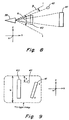
- a light sensor 38 in the form of a television camera can be seen sensing three individual objects 40, 41 and 42. It is seen that the apparent sizes of objects 40 and 41 are not determined by their true sizes, but by the angles they subtend from the perspective of the television camera.
- the full vertical height x of object 42 is proportional to the screen height w, the angle ⁇ , and the angle of arrival ⁇ of a beam of light reflected from object 42.
- the angle of arrival of a reflected beam of light from any point in the field of view can be measured with respect to any desired reference.
- the angular size of the field of view ⁇ is determined by the length of the lens and the size of the image detector utilized in the television camera.
- the total screen height w is a known parameter of the image detector and the coordinates of the image of any point B may be determined by computer image processing.
- Figs. 8 and 9 illustrate angle measurements in only one axis, the Z-axis, with the objects rotated about the X-axis. Conversely, horizontal measurements in the image would correspond to measuring angles produced when rotating the objects 40, 41 and 42 about the Z-axis.
- the determination of the orientation of an object rotated about the Y-axis the determination is readily obtained by determining the relative positions of two points on the image of object 41 from which their relative position would determine the Y-axis orientation.
- object 40 is arranged vertically and that object 41 is rotated slightly about the Y-axis.
- the determination of the locations of corners c and d of object 41 would indicate the Y-axis orientation thereof.
- the X and Z axis rotations which are difficult to measure with the techniques of the prior art while sensing along the Y-axis.
- the measurement of the X and Z axes rotations for which the present invention is suited.
- the application of one specular-dome reflector 10 would facilitate the measurement of angular orientation during rotation about the X and Z axes.
- the application of two properly arranged arcuate double reflectors 16 would facilitate the measurement of angular orientation during rotations about the X and Z axes.
- a method of utilization of the specular-dome reflector 10 can be seen.
- the object 34 shown in phantom
- the object 34 is shown with a specular-dome reflector 10 coupled thereto to provide the reflection of a beam of light projected from the light source 36 and detected by the light sensor 38.
- centroid 13 of reflection detected by the light sensor 38 corresponding to each angular orientation, is indicated by points a, b and c in Figs. 10A-D. It is to be noted that only one centroid 13 of reflection is detected at a time corresponding to a specific angular orientation of the object 34. Thus, the distance between the centroids 13 of the reflections from point a , representing ⁇ - 0°, are indicated as lengths e and f and the total size of the specular-dome reflector 10 is indicated as length d.
- the location of the centroids 13 of the reflections on the specular-dome reflector 10, specifically points a, b and c can generally be represented by the variable X, wherein X is the point at which the surface normal bisects the beam of light from the light source 36 to X and from X to the light sensor 38. Therefore, X would represent the varying centroid 13 of reflection in correspondence to the angular orientation to which the object 34 is rotated.
- the mathematical relationship between the orientation of the object 34 and the location of varying point X is determined by geometry, although quite complex geometries.
- the direct calculation becomes easily tractable.
- the required conditions are: (1) that the light source 36 and light sensor 38 be spatially positioned far from the specular-dome reflector 10 in relation to the size of the specular-dome reflector 10 (that is, L in Fig. 10A is large relative to D in Fig. 11); and (2) that the specular-dome reflector 10 has a nearly constant exterior curvature side 12.
- angles of arrival of reflections from a retro reflector are determined in a similar manner as discussed above. Hence, the angles of arrival determined from a combination of the specular-dome reflector 10 or arcuate double reflector 16 in combination with a retro reflector 14 are similarly obtained wherein the distance between the points of reflection is determined by obtaining the angles of arrival in accordance with the above described procedure.
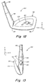
- the golf club 44 can be seen to include a shaft 46, a hosel 48 and a head 50.
- the hosel 48 and head 50 are integral and the shaft 46 is coupled to the hosel 48.
- the head 50 further includes a face 52, a back 54, a toe 56 and a heel 58.
- the head 50 can be seen to further include orientation dependent reflectors, in the form of specular dome reflectors 62 and 64.
- the specular-dome reflectors 62 and 64 are shown further having orientation independent reflectors 63 coupled respectively thereto.
- the specular-dome reflector 62 facilitates angular orientation measurements for "pitch” and "yaw” in the Y and X axes respectively.
- the specular-dome reflector 64 facilitates angular orientation measurements in the X-axis for "lie”.
- FIG. 14 illustrates a package 66 being moved along and about in some stage of a multi-part process wherein angular orientation is important.
- the specular-dome reflectors 70 and 72, as positioned in Fig. 14, would provide angular orientation measurement in the X and Z axes and the Y and Z axes, respectively.
Landscapes
- Physics & Mathematics (AREA)
- Electromagnetism (AREA)
- Engineering & Computer Science (AREA)
- General Physics & Mathematics (AREA)
- Radar, Positioning & Navigation (AREA)
- Remote Sensing (AREA)
- Computer Networks & Wireless Communication (AREA)
- Length Measuring Devices By Optical Means (AREA)
Claims (19)
- Système optique pour déterminer l'orientation angulaire d'un objet dans une plage de rotation autour d'au moins un axe de rotation, le système optique comprenant en combinaison :caractérisé en ce que :un moyen de réflexion dépendant de l'orientation devant être couplé à l'objet, une source lumineuse et un moyen de détection de lumière, le moyen de source lumineuse (36) fournissant un faisceau de lumière détectable optiquement en direction du moyen de réflexion dépendant de l'orientation,le moyen de réflexion dépendant de l'orientation (10, 16) fournit une réflexion optique ayant au moins une propriété détectable correspondant à un point de réflexion sur une surface du moyen de réflexion dépendant de l'orientation qui varie en position en fonction d'une rotation du moyen de réflexion dépendant de l'orientation autour d'au moins un des au moins un axe de rotation ; etle moyen de détection de lumière (38) est prévu pour détecter des réflexions optiques sur ledit moyen de réflexion dépendant de l'orientation afin de faciliter la détermination de l'orientation angulaire, le moyen de détection de lumière étant positionné de façon adjacente au moyen de source lumineuse, de sorte que au moins le point de réflexion y est déterminé par le moyen de détection de lumière et que l'orientation angulaire de l'objet est déterminée.
- Système optique selon la revendication 1, comprenant en outre un moyen de réflexion indépendant de l'orientation (14) pour fournir une réflexion optique qui correspond à un point constant de référence, ledit moyen de réflexion indépendant de l'orientation étant couplé de façon fixe audit moyen de réflexion dépendant de l'orientation de sorte que lesdits moyens de réflexion fournissent simultanément des réflexions optiques qui varient en distance entre elles en correspondance avec des orientations angulaires particulières.
- Système optique selon les revendications 1 ou 2, dans lequel le moyen de réflexion dépendant de l'orientation est constitué d'un réflecteur à dôme spéculaire (10) ayant un côté à courbure extérieure (12) faisant face au moyen de source lumineuse, par lequel le réflecteur à dôme spéculaire peut faciliter la détermination de l'orientation angulaire d'un objet par rapport à deux axes de rotation.
- Système optique selon les revendications 1 ou 2, dans lequel le moyen de réflexion dépendant de l'orientation est constitué d'un double réflecteur courbe (16), le double réflecteur courbe comprenant un corps allongé (18) ayant un côté extérieur (22), et des première et seconde parties faisant un angle (24, 26) ayant sur elles des première et seconde surfaces réfléchissantes spéculaires respectives (28, 30) couplées au côté extérieur de sorte que les première et seconde surfaces réfléchissantes s'opposent entre-elles angulairement et convergent pour former un angle droit entre elles, par lequel les première et seconde surface réfléchissantes spéculaires coopèrent pour réfléchir optiquement le faisceau lumineux pour ainsi faciliter la détermination de l'orientation angulaire par rapport à un axe de rotation s'étendant perpendiculairement au corps allongé.
- Dispositif selon la revendication 4, dans lequel ledit corps allongé (18) et lesdites première et seconde parties faisant un angle du double réflecteur courbe forment un seul bloc.
- Système optique selon l'une quelconque des revendications 2 à 4, dans lequel le moyen de réflexion indépendant de l'orientation est constitué d'un retroréflecteur (14), le rétroréflecteur facilitant la réflexion du faisceau de lumière vers l'arrière en direction du moyen de source lumineuse parallèlement à la direction d'arrivée du faisceau lumineux.
- Système optique selon l'une quelconque des revendications 1 à 6, dans lequel ledit moyen de détection de lumière détermine le point de réflexion sur le moyen de réflexion dépendant de l'orientation en détectant l'angle d'arrivée du faisceau lumineux réfléchi détectable optiquement.
- Système optique selon l'une quelconque des revendications 1 à 7, dans lequel la au moins une propriété comprend un centroïde de la réflexion optique.
- Système optique selon la revendication 8, dans lequel le moyen de détection de lumière détermine le point de réflexion correspondant au centroïde de la réflexion optique.
- Procédé pour déterminer optiquement l'orientation angulaire d'un objet dans une plage de rotation autour d'au moins un axe de rotation, le procédé comprenant les étapes suivantes :caractérisé en ce que la au moins une réflexion optique dépendant de l'orientation possède au moins une propriété correspondant à un point de réflexion qui varie en position sur une surface de l'objet en correspondance avec des orientations angulaires particulières de l'objet autour du au moins un axe de rotation.projection d'un faisceau lumineux détectable optiquement en direction de l'objet ;production d'au moins une réflexion optique dépendant de l'orientation du faisceau lumineux provenant de l'objet ;détection de la au moins une réflexion optique dépendant de l'orientation à partir d'un premier emplacement adjacent vers un second emplacement à partir duquel le faisceau lumineux est projeté ; etdétermination de l'orientation angulaire de l'objet sur la base de la au moins une réflexion optique dépendant de l'orientation,
- Procédé selon la revendication 10, dans lequel l'étape de détermination de l'orientation angulaire comprend en outre les étapes suivantes :déterminer un angle d'arrivée de la au moins une réflexion optique dépendant de l'orientation ;déterminer au moins un point de réflexion sur l'objet sur la base de l'angle d'arrivée ; etdéterminer l'orientation angulaire sur la base du au moins un point de réflexion.
- Procédé selon les revendications 10 ou 11, comprenant en outre les étapes suivantes :production d'au moins une réflexion optique indépendante de l'orientation du faisceau lumineux provenant de l'objet, la au moins une réflexion optique indépendante de l'orientation correspondant à un point de référence constant sur l'objet ;détection de la au moins une réflexion optique indépendante de l'orientation ;détermination d'une distance de séparation entre la au moins une réflexion optique indépendante de l'orientation et la au moins une réflexion optique dépendant de l'orientation ; etdétermination de l'orientation angulaire de l'objet sur la base de la distance de séparation.
- Procédé selon l'une quelconque des revendications 10 à 12, dans lequel l'étape de production d'au moins une réflexion optique dépendant de l'orientation comprend une étape de coupler un réflecteur à dôme spéculaire (10) à l'objet, le réflecteur à dôme spéculaire ayant un côté à courbure extérieure (12) faisant face au faisceau lumineux projeté en direction de l'objet.
- Procédé selon l'une quelconque des revendications 10 à 12, dans lequel l'étape de production d'au moins une réflexion optique dépendant de l'orientation comprend une étape de coupler un double réflecteur courbe (16) à l'objet, le double réflecteur courbe comprenant un corps allongé (18) ayant un côté extérieur (22), et des première et seconde parties faisant un angle (24, 26) ayant sur elles des première et seconde surfaces réfléchissantes spéculaires (28, 30) couplées audit côté extérieur, de sorte que les première et seconde surfaces réfléchissantes spéculaires s'opposent en faisant un angle entre elles et convergent pour former un angle droit entre elles, par lequel les première et seconde surfaces réfléchissantes spéculaires coopèrent pour réfléchir optiquement le faisceau lumineux afin de faciliter une détermination de l'orientation angulaire de l'objet par rapport à un axe de rotation s'étendant perpendiculairement au corps allongé.
- Procédé selon l'une quelconque des revendications 12 à 14, dans lequel l'étape de production d'au moins une réflexion optique indépendante de l'orientation comprend une étape de coupler au moins un rétroréflecteur (14) à l'objet, le au moins un rétroréflecteur étant placé de façon à faire face au faisceau lumineux projeté en direction de l'objet, le retroréflecteur réfléchissant la au moins une réflexion optique indépendante de l'orientation parallèlement à une direction d'arrivée du faisceau lumineux.
- Procédé selon l'une quelconque des revendications 10 à 15, dans lequel l'étape de détermination de l'orientation angulaire de l'objet comprend en outre les étapes de :modifier au moins une propriété détectable du faisceau lumineux de sorte que la au moins une propriété détectable soit communiquée à la au moins une réflexion optique dépendant de l'orientation et covarie avec la position de la au moins une réflexion optique dépendant de l'orientation ; etdétecter la au moins une propriété détectable de la au moins une réflexion optique dépendant de l'orientation.
- Procédé selon la revendication 16, dans lequel au moins une propriété détectable du faisceau lumineux est une polarisation du faisceau lumineux.
- Procédé selon les revendications 16 ou 17, dans lequel au moins une propriété détectable du faisceau lumineux est un spectre colorimétrique du faisceau lumineux.
- Procédé selon l'une quelconque des revendications 10 à 15, dans lequel l'action de déterminer l'orientation angulaire de l'objet comprend une action de déterminer un point de réflexion correspondant à un centroïde de la réflexion optique dépendant de l'orientation.
Applications Claiming Priority (1)
| Application Number | Priority Date | Filing Date | Title |
|---|---|---|---|
| PCT/US1999/011451 WO2000072047A1 (fr) | 1999-05-24 | 1999-05-24 | Appareil et procede pour definir l'orientation angulaire d'un objet |
Publications (3)
| Publication Number | Publication Date |
|---|---|
| EP1210619A1 EP1210619A1 (fr) | 2002-06-05 |
| EP1210619B1 true EP1210619B1 (fr) | 2005-11-09 |
| EP1210619B8 EP1210619B8 (fr) | 2006-01-18 |
Family
ID=22272826
Family Applications (1)
| Application Number | Title | Priority Date | Filing Date |
|---|---|---|---|
| EP99925789A Expired - Lifetime EP1210619B8 (fr) | 1999-05-24 | 1999-05-24 | Appareil et procede pour definir l'orientation angulaire d'un objet |
Country Status (5)
| Country | Link |
|---|---|
| EP (1) | EP1210619B8 (fr) |
| JP (1) | JP2003500659A (fr) |
| AU (1) | AU4200799A (fr) |
| DE (1) | DE69928298T2 (fr) |
| WO (1) | WO2000072047A1 (fr) |
Cited By (1)
| Publication number | Priority date | Publication date | Assignee | Title |
|---|---|---|---|---|
| CN102608074A (zh) * | 2012-03-21 | 2012-07-25 | 中国科学院安徽光学精密机械研究所 | 一种新型双向反射分布函数测量装置 |
Families Citing this family (4)
| Publication number | Priority date | Publication date | Assignee | Title |
|---|---|---|---|---|
| JP4806574B2 (ja) * | 2006-02-17 | 2011-11-02 | 株式会社ジャパーナ | ゴルフアドレスのズレ検出装置 |
| US11284964B2 (en) | 2013-08-13 | 2022-03-29 | Brainlab Ag | Moiré marker device for medical navigation |
| EP3035880A1 (fr) | 2013-08-13 | 2016-06-29 | Brainlab AG | Outil numérique et procédé pour planifier un remplacement de genou |
| GB2551535A (en) * | 2016-06-21 | 2017-12-27 | Alexander Borrie John | A golf swing analyser |
Family Cites Families (2)
| Publication number | Priority date | Publication date | Assignee | Title |
|---|---|---|---|---|
| FR2488396A1 (fr) * | 1980-08-07 | 1982-02-12 | Onera (Off Nat Aerospatiale) | Procede et dispositifs optiques pour la determination d'un parametre d'attitude d'un corps |
| US4652917A (en) * | 1981-10-28 | 1987-03-24 | Honeywell Inc. | Remote attitude sensor using single camera and spiral patterns |
-
1999
- 1999-05-24 JP JP2000620381A patent/JP2003500659A/ja active Pending
- 1999-05-24 WO PCT/US1999/011451 patent/WO2000072047A1/fr not_active Ceased
- 1999-05-24 AU AU42007/99A patent/AU4200799A/en not_active Abandoned
- 1999-05-24 EP EP99925789A patent/EP1210619B8/fr not_active Expired - Lifetime
- 1999-05-24 DE DE69928298T patent/DE69928298T2/de not_active Expired - Fee Related
Cited By (2)
| Publication number | Priority date | Publication date | Assignee | Title |
|---|---|---|---|---|
| CN102608074A (zh) * | 2012-03-21 | 2012-07-25 | 中国科学院安徽光学精密机械研究所 | 一种新型双向反射分布函数测量装置 |
| CN102608074B (zh) * | 2012-03-21 | 2014-09-24 | 中国科学院安徽光学精密机械研究所 | 一种新型双向反射分布函数测量装置 |
Also Published As
| Publication number | Publication date |
|---|---|
| DE69928298D1 (de) | 2005-12-15 |
| DE69928298T2 (de) | 2006-08-10 |
| WO2000072047A1 (fr) | 2000-11-30 |
| JP2003500659A (ja) | 2003-01-07 |
| AU4200799A (en) | 2000-12-12 |
| EP1210619B8 (fr) | 2006-01-18 |
| EP1210619A1 (fr) | 2002-06-05 |
Similar Documents
| Publication | Publication Date | Title |
|---|---|---|
| US5936722A (en) | Apparatus and method for determining the angular orientation of an object | |
| JP3511450B2 (ja) | 光学式測定装置の位置校正方法 | |
| EP3619498B1 (fr) | Scanner de triangulation ayant une géométrie plate et projetant des points non codés | |
| US7312862B2 (en) | Measurement system for determining six degrees of freedom of an object | |
| CN103403575B (zh) | 靶标设备和方法 | |
| US7634128B2 (en) | Stereoscopic three-dimensional metrology system and method | |
| JP2564963B2 (ja) | ターゲット及びこれを用いた三次元位置姿勢計測システム | |
| JP3070953B2 (ja) | 空間座標の逐点式測定方法及びシステム | |
| US7319511B2 (en) | Surveying instrument and electronic storage medium | |
| US20050068523A1 (en) | Calibration block and method for 3D scanner | |
| JPH08500460A (ja) | ロボットで運ばれるセンサーや道具のような可動物体の3次元における位置を特定する方法及び装置 | |
| US20020171847A1 (en) | Three-dimensional shape-measuring system | |
| JP2004170412A (ja) | 測定系の較正のための方法と装置 | |
| WO2010069160A1 (fr) | Appareil de mesure d'orientation d'objet dans six dimensions | |
| JP2000230818A (ja) | 車輪アライメント特性の非接触式測定方法とその測定装置 | |
| US11754386B2 (en) | Method and system for capturing and measuring the position of a component with respect to a reference position and the translation and rotation of a component moving relative to a reference system | |
| EP2138803A1 (fr) | Gabarit pour mesurer la forme d'un objet et procédé pour mesurer une forme tridimensionnelle | |
| JP2018522240A (ja) | アーチファクトを測定するための方法 | |
| EP1210619B1 (fr) | Appareil et procede pour definir l'orientation angulaire d'un objet | |
| US5481361A (en) | Method of and device for measuring position coordinates | |
| US20080123110A1 (en) | Multifaceted digitizer adapter | |
| CN111707446B (zh) | 光斑中心与探测器接收面中心对准的调节方法及系统 | |
| CN114663486A (zh) | 一种基于双目视觉的建筑物测高方法及系统 | |
| JPH04313106A (ja) | ロボットアーム相対姿勢補正方法 | |
| Breuckmann et al. | 3D-metrologies for industrial applications |
Legal Events
| Date | Code | Title | Description |
|---|---|---|---|
| PUAI | Public reference made under article 153(3) epc to a published international application that has entered the european phase |
Free format text: ORIGINAL CODE: 0009012 |
|
| 17P | Request for examination filed |
Effective date: 20011221 |
|
| AK | Designated contracting states |
Kind code of ref document: A1 Designated state(s): DE FR GB |
|
| DAX | Request for extension of the european patent (deleted) | ||
| 17Q | First examination report despatched |
Effective date: 20030605 |
|
| GRAP | Despatch of communication of intention to grant a patent |
Free format text: ORIGINAL CODE: EPIDOSNIGR1 |
|
| DAX | Request for extension of the european patent (deleted) | ||
| GRAS | Grant fee paid |
Free format text: ORIGINAL CODE: EPIDOSNIGR3 |
|
| GRAA | (expected) grant |
Free format text: ORIGINAL CODE: 0009210 |
|
| AK | Designated contracting states |
Kind code of ref document: B1 Designated state(s): DE FR GB |
|
| REG | Reference to a national code |
Ref country code: GB Ref legal event code: FG4D |
|
| RIN2 | Information on inventor provided after grant (corrected) |
Inventor name: ARMSTRONG, BRIAN S. R. Inventor name: SCHMIDT, KARL B. |
|
| REF | Corresponds to: |
Ref document number: 69928298 Country of ref document: DE Date of ref document: 20051215 Kind code of ref document: P |
|
| PG25 | Lapsed in a contracting state [announced via postgrant information from national office to epo] |
Ref country code: GB Free format text: LAPSE BECAUSE OF NON-PAYMENT OF DUE FEES Effective date: 20060524 |
|
| ET | Fr: translation filed | ||
| PLBE | No opposition filed within time limit |
Free format text: ORIGINAL CODE: 0009261 |
|
| STAA | Information on the status of an ep patent application or granted ep patent |
Free format text: STATUS: NO OPPOSITION FILED WITHIN TIME LIMIT |
|
| 26N | No opposition filed |
Effective date: 20060810 |
|
| PG25 | Lapsed in a contracting state [announced via postgrant information from national office to epo] |
Ref country code: DE Free format text: LAPSE BECAUSE OF NON-PAYMENT OF DUE FEES Effective date: 20061201 |
|
| GBPC | Gb: european patent ceased through non-payment of renewal fee |
Effective date: 20060524 |
|
| REG | Reference to a national code |
Ref country code: FR Ref legal event code: ST Effective date: 20070131 |
|
| PG25 | Lapsed in a contracting state [announced via postgrant information from national office to epo] |
Ref country code: FR Free format text: LAPSE BECAUSE OF NON-PAYMENT OF DUE FEES Effective date: 20060531 |