EP1210882A2 - Equipement personnalisé pour casque muni d'une cagoule de protection - Google Patents
Equipement personnalisé pour casque muni d'une cagoule de protection Download PDFInfo
- Publication number
- EP1210882A2 EP1210882A2 EP01310145A EP01310145A EP1210882A2 EP 1210882 A2 EP1210882 A2 EP 1210882A2 EP 01310145 A EP01310145 A EP 01310145A EP 01310145 A EP01310145 A EP 01310145A EP 1210882 A2 EP1210882 A2 EP 1210882A2
- Authority
- EP
- European Patent Office
- Prior art keywords
- helmet
- protective hood
- crown
- pad
- panel
- Prior art date
- Legal status (The legal status is an assumption and is not a legal conclusion. Google has not performed a legal analysis and makes no representation as to the accuracy of the status listed.)
- Granted
Links
Images


Classifications
-
- A—HUMAN NECESSITIES
- A42—HEADWEAR
- A42C—MANUFACTURING OR TRIMMING HEAD COVERINGS, e.g. HATS
- A42C2/00—Manufacturing helmets by processes not otherwise provided for
- A42C2/007—Manufacturing custom-sized helmets
-
- A—HUMAN NECESSITIES
- A42—HEADWEAR
- A42B—HATS; HEAD COVERINGS
- A42B3/00—Helmets; Helmet covers ; Other protective head coverings
- A42B3/04—Parts, details or accessories of helmets
- A42B3/10—Linings
- A42B3/14—Suspension devices
- A42B3/145—Size adjustment devices
-
- A—HUMAN NECESSITIES
- A62—LIFE-SAVING; FIRE-FIGHTING
- A62B—DEVICES, APPARATUS OR METHODS FOR LIFE-SAVING
- A62B18/00—Breathing masks or helmets, e.g. affording protection against chemical agents or for use at high altitudes or incorporating a pump or compressor for reducing the inhalation effort
- A62B18/04—Gas helmets
Definitions
- the invention relates to a custom fitting assembly for a helmet equipped with a protective hood.
- the system is particular suited for use with helmet mounted devices which support military air and ground operations.
- helmets are designed to meet requirements for comfort, stability, and head impact protection during flight, egress and ejection, and to fit an anthropometric range of heads.
- HMDs helmet mounted devices
- HMD Helmet Mounted Display
- an inner helmet assembly in just a few sizes which could be easily custom-fitted to military personnel for use with various outer helmet systems for a variety of modem combat applications.
- Such an inner helmet would figuratively lock onto the wearer's head thereby insuring reproducible alignment of the "eyebox" to the eventual HMD.
- the preferred embodiments of the invention therefore provide a helmet fitting assembly in one or two sizes with custom-fitted inserts that can be adapted to various helmets.
- the preferred embodiments allow easy positioning of the helmet with positive locking devices.
- the preferred embodiments provide an insert which is molded or formed in situ to conform to a portion of the wearer's head.
- the preferred helmet is equipped with a hood that provides protection against chemical agents and biological agent, as may occur during chemical or biological warfare or industrial accidents.
- a semi-rigid suspension system of independent components which contacts the head over large surface areas.
- the system includes a custom-contoured component and positive lock components which cooperatively allow repeated engagement of the desired design eye position.
- the preferred embodiment of the system revolves around an inner helmet comprising a front forehead dome and side sections.
- a semi-rigid rear panel engages the wearer's nape and has adjusting straps which extend generally forwardly to engage positive locking clips located on the inner helmet side sections.
- the inner helmet is positioned in the fore and aft directions by the rear panel adjusting straps.
- a contoured pad then supports the forehead dome on the user's forehead.
- the contoured pad includes an inner comfort layer, a primary layer which is custom fitted in situ, and an outer impact absorbing layer. Because the primary layer is essentially a mold of the wearer's forehead it always seats in the same position.
- a semi-rigid crown pad has adjusting straps which extend generally downward to engage positive locking clips located on the inner helmet side panels.
- the inner helmet assembly is suspended from the crown pad via the straps which are adjusted to bring the inner helmet to the desired vertical position.
- the inner helmet is restricted from upward movement by a chin strap or breathing mask.
- the components of the helmet fitting assembly are adjusted along the horizontal and vertical axes to position the wearer's eyes in the proper orientation and distance from the ultimate display.
- the helmet fitting assembly also resists forward rotation caused by the weight of the display systems located in front of the wearer's forehead within the helmet. Forward rotation is characterized by the forehead dome sliding down while the rear portion of the helmet rides up. These forces are resisted by the brow pad which is molded to a particular part of the forehead, the nape panel, and by the chin strap or breathing mask which opposes any tendency of the rear part of the helmet to pivot away from the wearer's chin.
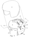
- Outer helmet 10 may, for example, be formed of ballistic material of any suitable type known to the art to afford the wearer protection against injury from flying fragments and the like.
- Outer helmet 10 may consist of a basic protective helmet for infantry, a standard helmet for air crew provided with visors, or an advanced helmet for air crew provided with HMD technologies.
- Inner helmet 20 may be permanently attached within outer helmet 10, for example, by screws or adhesives.
- inner helmet 20 may be clipped, latched or otherwise removable secured within outer helmet 10, for example by an interchangeable latch assembly described in a commonly-owned, copending patent application Serial No. 09/640,442 filed on August 17, 2000.
- Total weight for the inner helmet and on HMD equipped outer helmet is in the order of 4 1/2 lbs.
- Inner helmet 20 is a rigid frame made of a strong yet lightweight material, for example, graphite or fiberglass.
- Inner helmet 20 is characterized by a broad forehead dome 21, side sections 22a and 22b, a rear panel 25 and a crown aperture 26.
- Side section 22a includes a first pair of retention clips 23a and 23b and a second pair of retention clips 23c and 23d.
- a similar set of retention clips are mounted onto side panel 22b.
- a chin strap 19 extends between the lower portions of side panels 22a and 22b.
- a crown pad 50 which will be described in greater detail below, includes adjusting straps that extend through slots 24c and 24d and into respective retention clips. These adjusting straps permit vertical positioning of inner helmet 20 relative to the crown of the wearer's head.
- a breathing mask may be attached to side panels 22a and 22b via adjustable length straps 27a. While not shown for the sake of clarity, the central portion of each side panel may comprise a depression for accommodating ear phones.
- a brow pad 30 Adjacent the interior of forehead dome 21 is a brow pad 30 which will be discussed in greater detail below in connection with FIGS. 3A and 3B.
- a rear pad 25a of impact absorbing material is attached to the interior of rear panel 25.
- Interior of rear pad 25a is a nape panel 40 which will be discussed in greater detail in connection with FIGS. 4A and 4B.
- the adjusting straps of nape panel 40 are employed to set the fore and aft position of inner helmet 20 with respect to the nape of the wearer's neck.
- Brow pad 30 is subsequently fitted to the contours of the wearer's forehead.
- Points within brow pad 30, nape panel 40 and chin strap 19 or breathing mask 27 form the apices of an imaginary triangle 28.
- leg 28a of triangle 28 assumes a fixed length.
- chin strap 19 or breathing mask 27 essentially fixes the distance of legs 28b and 28c.
- the significance of the fixed triangle geometry is as follows.
- the straps of nape panel 40 and crown pad 50 may be adjusted to establish a particular exit pupil distance for an outer helmet mounted display (HMD).
- HMD outer helmet mounted display
- the position is retained by brow pad 30 which fills the entire space between forehead dome 21 and the wearer's forehead.
- An outer helmet mounted display typically adds significant weight to the front portion of the helmet. Such weight is evenly distributed across large surface areas via brow pad 30 and crown pad 50. The moment of this forwardly-mounted weight generally urges forehead dome 21 downwardly over the wearer's eyes. Since leg 28a is of a fixed length, such movement would require nape panel 40 to pivot counter-clockwise. However, since leg 28b is of fixed length the torque applied to nape panel 40 is resisted by chin strap 19.
- FIG. 2B is another cross-sectional view showing a protective hood 70 that is completely integrated with the components of the custom fitting assembly.
- the hood forms a protective bubble around the head.
- FIG. 2B illustrates the positioning of protective hood 70 with respect to the nape panel 40 and crown pad 50, both of which shall be generically referred to as support panels.
- Brow pad 30 is first fitted and then placed inside hood 70.
- Nape panel 40 and crown pad 50 are also placed inside hood 70 with their straps located outside hood 70.
- Hood 70 is sealed around the pivotal connection between the support panels and their straps, as will be described in further detail below.
- the straps are shown in dotted line indicating that in the view of FIG. 2B they are behind hood 70.
- a visor 74 having a visor periphery 74a.
- a visor duct 74b is disposed within periphery 74a and is fed ventilating air through the front or side of visor 74, for example, at a location 74c outside the hood.
- a respiration system 76 having the following conventional components: a stiff outer shell 76a; a rubber inner facepiece 76b; a breathing air supply hose 76c; an exhalation valve 76d; a microphone cable 76e; a drink tube 76f; and adjustable length straps 27a and 27b removably coupling outer shell 76a to helmet side sections 22a and 22b.
- the hood is layered between outer shell 76a and inner facepiece 76b.
- Components 76c, 76d, 76e and 76f pass through holes in the hood and are secured to inner facepiece 76b, effectively clamping the hood between facepiece 76b and outer shell 76a.
- Hose 76c and the tubular portion of valve 76d may be secured to facepiece 76b with threaded nuts 76g and 76h, for example. Any openings between the holes and the components are filled with an appropriate sealant.
- a pair of earphones 78 are placed inside the hood, whereby the hood provides increased attenuation of external ambient noise allowing improved communication.
- the earphones have a communications cable 78a which passes through a hole in the hood. Any opening between the hole and cable 78a is filled with an appropriate sealant.
- hood 70 has a lower edge 70a near which is attached a neck dam 70b.
- a shoulder shroud 70c may be attached onto lower edge 70a.
- Neck dam 70b is an air barrier preventing exchange of air between the head cavity and the atmosphere or the lower portion of a flight suit or other garment.
- a dump valve 70d is located above neck dam 70b for releasing excess pressure from within the head cavity.
- Shroud 70c may be attached to the flight suit or other garment with a slide fastener or simply tucked inside.
- Hood 70 is made from a chemically resistant and biologically resistant material, like rubber or butyl rubber. The hood is molded to the contours of the interior of the helmet.
- brow pad 30 comprising an outer pouch 31 equipped with a closeable flap 31a.
- Pouch 31 is removably affixed to the inner surface of forehead dome 21, for example, by hook and loop fasteners or other suitable means.
- Pouch 31 is made from a material which has characteristics of durability and comfort when contacting the wearer's skin, e.g. leather or other suitable materials.
- an outer liner 32 made of an impact absorbing material, for example, polystyrene, which conforms to the interior of forehead dome 21.
- an inner layer 34 made of compressible, comfort material, for example, foam rubber.
- the interior of pouch 31 is filled with a liquid foaming agent which expands and solidifies to conform to the contours of the wearer's forehead and the outer liner 32.
- a liquid foaming agent which expands and solidifies to conform to the contours of the wearer's forehead and the outer liner 32.
- an expandable foam may be used wherein the foaming agent in liquid form 33 is injected or poured into the interior of pouch 31 and expands to fill the cavity.
- a minimally exothermic polyurethane foam having a relatively fast rise time may be used, for example, foams made from polyether polyol resin combine with pre-reacted diphenylmethane diisocyanate.
- protective hood 70 is shown between forehead dome 21 and brow pad 30.
- Brow pad 30 is first fitted, as described above, in the absence of hood 70.
- Brow pad 30 is then placed inside hood 70 and attached with a hook and loop fastener to the hood 70 instead of forehead dome 21.
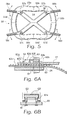
- nape panel 40 is shown comprising a semi-rigid frame 41 made, for example, from a composite resin. Very thin, flexible composite resin layers are laminated together resulting in lightweight, yieldable panels. Interior of frame 41 is a comfort layer 42 made from a compressible material, for example, foam rubber. Further interior is a cover layer 43 made from a comfortable, durable material, for example, leather. Cover layer 43 holds comfort layer 42 in place by extending through apertures 44 or around the outer perimeter where its edges are adhered on the exterior side of frame 41.
- FIG. 4B shows apertures 44 along with straps 46a, 46b, 46c and 46d which are attached respectively to four quadrants of nape panel 40 via pivoting connection points 47a, 47b, 47c and 47d.
- FIG. 4C shows the pivotal connection between the support panels and their straps in detail.
- a portion of comfort layer 42 is removed and a hole is formed in frame 41 to accommodate a threaded female post 80 which terminates at its left side in a retention plate 80a.
- Hood material 70 is fitted around post 80 with any openings being filled by an appropriate sealant.
- Strap 46 is pivotally connected to post 80 via screw 46e.
- the pivotal connections for both support panels are maintained with the hood material completely sealing the support panels therein.
- the benefit of this configuration is that the support panels, as well as the brow pad, serve to lift the hood material off the wearer's head providing greater comfort.
- This configuration also maintains the contact surfaces between the brow pad and the wearer as well as between the support panels and the wearer. Therefore, the wearer's head can be completely sealed against the environment while maintaining the reproducible alignment of the eyebox, which is critical for HMD systems.
- this lifting of the hood results in a gap 50c between webbing strips 50a and 50b of the support panel or a space 50d adjacent the support panel.
- a duct 90 having an exhaust vent 90a directed toward gap 50c or space 50d is provided.
- Duct 90 extends through a hole in the hood. Any spaces around the hole are filled with an appropriate sealant. Ventilating air is provided to duct 90 to cool the wearer's head.
- crown pad 50 has a similar construction to nape panel 40 including a semi-rigid frame 51, a comfort layer similar to 42 and a cover layer similar to 43.
- the cover layer has edges 53a and 53b which extend through apertures 54 before being adhered on the exterior surface of frame 51.
- Each of the quadrants 55a, 55b, 55c and 55d includes a strap 56a, 56b, 56c and 56d pivotally attached to frame 51 via screws 57a, 57b, 57c and 57d.
- the apertures create web-like strips in panel 40 and pad 50 that extend from the adjacent quadrants out to the strap connection points.
- FIG. 6A shows an exemplary bendable, plastic strap extending initially through a side panel slot 24 formed within side panel 22a or 22b and further through clip frame 60 made of rugged plastic.
- Mounting screws 61 secure clip frame 60 to the exterior of side panel 22.
- Extending outwardly from clip frame 60 is a cantilevered retention arm 62 having a fixed end 62b and a free end 62c with downwardly extending wedges 62a therebetween.
- Locking element 63 as can be seen more clearly in FIG. 6B is slideably mounted to clip frame 60. Locking element 63 is slideable in direction 62d from a position adjacent rear stop 62e, over detent 62f, to a position adjacent front stop 62g.
- FIG. 2 shows a positioning fixture 29 with a reference point 29a.
- Positioning fixture 29 is dimensioned and configured to align reference point 29a on the exact line of sight of the ultimate display.
- the crown pad straps and nape panel straps are adjusted in 2mm increments to locate reference point 29a directly in front of the wearer's eyes at a predetermined distance. If a strap is inserted too far through clip 60, free end 62c is raised and the strap is retracted. Once aligned, locking elements 63 are moved to their locking positions over free ends 62c. While maintaining the aligned position on the wearer's head, brow pad 30 is filled with the appropriate amount of foaming agent. The resulting foam 33 expands to fill the gap and press the head firmly against nape panel 40.
- Brow pad 30 and nape panel 40 are generally diametrically opposed. Accordingly, the inner helmet may be easily donned and doffed while simultaneously reestablishing the exact eyebox alignment every time. Upon tightening chin strap 19, the inner helmet assembly becomes locked in position on the head. Centrifuge testing was performed with head movements up to 4G and forwardly-positioned stationery head positioning up to 9G. Overall the approximately 4 1/2 lbs. complete inner/outer helmet was displaced a maximum of 4mm with the average for 10 aircrew between 1.5 and 3mm.
Landscapes
- Health & Medical Sciences (AREA)
- Engineering & Computer Science (AREA)
- Manufacturing & Machinery (AREA)
- Pulmonology (AREA)
- General Health & Medical Sciences (AREA)
- Business, Economics & Management (AREA)
- Emergency Management (AREA)
- Helmets And Other Head Coverings (AREA)
Applications Claiming Priority (2)
| Application Number | Priority Date | Filing Date | Title |
|---|---|---|---|
| US729119 | 1991-07-12 | ||
| US09/729,119 US6401259B1 (en) | 2000-02-02 | 2000-12-04 | Custom fitting assembly for helmet with protective hood |
Publications (3)
| Publication Number | Publication Date |
|---|---|
| EP1210882A2 true EP1210882A2 (fr) | 2002-06-05 |
| EP1210882A3 EP1210882A3 (fr) | 2003-11-12 |
| EP1210882B1 EP1210882B1 (fr) | 2006-04-05 |
Family
ID=24929663
Family Applications (1)
| Application Number | Title | Priority Date | Filing Date |
|---|---|---|---|
| EP01310145A Expired - Lifetime EP1210882B1 (fr) | 2000-12-04 | 2001-12-04 | Equipement personnalisé pour casque muni d'une cagoule de protection |
Country Status (4)
| Country | Link |
|---|---|
| EP (1) | EP1210882B1 (fr) |
| AT (1) | ATE322185T1 (fr) |
| DE (1) | DE60118499T2 (fr) |
| ZA (1) | ZA200109968B (fr) |
Cited By (2)
| Publication number | Priority date | Publication date | Assignee | Title |
|---|---|---|---|---|
| GB2409817A (en) * | 2004-01-12 | 2005-07-13 | Helmet Integrated Syst Ltd | Fitted cap for use in helmet |
| CN113398503A (zh) * | 2021-05-17 | 2021-09-17 | 中国人民解放军火箭军特色医学中心 | 一种火箭推进剂作业用防护罩 |
Families Citing this family (5)
| Publication number | Priority date | Publication date | Assignee | Title |
|---|---|---|---|---|
| US8296868B2 (en) | 2007-08-17 | 2012-10-30 | Easton Sports, Inc. | Adjustable hockey helmet |
| DE102010009666A1 (de) * | 2010-02-27 | 2011-09-01 | Fraunhofer-Gesellschaft zur Förderung der angewandten Forschung e.V. | Vorrichtung zum Befeuchten der Atemluft eines Benutzers und ihre Verwendung |
| US9345282B2 (en) | 2011-07-27 | 2016-05-24 | Bauer Hockey, Inc. | Adjustable helmet for a hockey or lacrosse player |
| US11768538B1 (en) | 2019-04-26 | 2023-09-26 | Apple Inc. | Wearable electronic device with physical interface |
| WO2022016040A1 (fr) * | 2020-07-17 | 2022-01-20 | Milwaukee Electric Tool Corporation | Casque de protection pourvu d'un système de sangle |
Family Cites Families (8)
| Publication number | Priority date | Publication date | Assignee | Title |
|---|---|---|---|---|
| US3843970A (en) * | 1973-03-19 | 1974-10-29 | M Marietta | Protective headgear |
| US4833735A (en) * | 1987-07-01 | 1989-05-30 | Gentex Corporation | Helmet suspension with integrated crown straps and headband |
| GB9016106D0 (en) * | 1990-07-23 | 1990-09-05 | Helmets Ltd | Helmet liner |
| US5245993A (en) * | 1991-10-31 | 1993-09-21 | The Boeing Company | Pilot's ensemble with integrated threat protection |
| FR2686795B1 (fr) * | 1992-01-30 | 1996-07-05 | Intertechnique Sa | Equipement individuel respiratoire et de protection en ambiance contaminee. |
| US5315718A (en) * | 1992-04-30 | 1994-05-31 | The United States Of America As Represented By The Secretary Of The Army | Protective helmet and retention system therefor |
| US5584073A (en) * | 1995-04-12 | 1996-12-17 | Gentex Corporation | Integrated helmet system |
| US6279172B1 (en) * | 2000-02-02 | 2001-08-28 | Gentex Corporation | Custom fitting assembly for helmet |
-
2001
- 2001-12-04 DE DE60118499T patent/DE60118499T2/de not_active Expired - Fee Related
- 2001-12-04 AT AT01310145T patent/ATE322185T1/de not_active IP Right Cessation
- 2001-12-04 ZA ZA200109968A patent/ZA200109968B/xx unknown
- 2001-12-04 EP EP01310145A patent/EP1210882B1/fr not_active Expired - Lifetime
Cited By (4)
| Publication number | Priority date | Publication date | Assignee | Title |
|---|---|---|---|---|
| GB2409817A (en) * | 2004-01-12 | 2005-07-13 | Helmet Integrated Syst Ltd | Fitted cap for use in helmet |
| GB2409817B (en) * | 2004-01-12 | 2009-02-18 | Helmet Integrated Syst Ltd | Headgear |
| CN113398503A (zh) * | 2021-05-17 | 2021-09-17 | 中国人民解放军火箭军特色医学中心 | 一种火箭推进剂作业用防护罩 |
| CN113398503B (zh) * | 2021-05-17 | 2022-04-26 | 中国人民解放军火箭军特色医学中心 | 一种火箭推进剂作业用防护罩 |
Also Published As
| Publication number | Publication date |
|---|---|
| DE60118499T2 (de) | 2006-09-07 |
| ATE322185T1 (de) | 2006-04-15 |
| ZA200109968B (en) | 2002-06-27 |
| EP1210882A3 (fr) | 2003-11-12 |
| EP1210882B1 (fr) | 2006-04-05 |
| DE60118499D1 (de) | 2006-05-18 |
Similar Documents
| Publication | Publication Date | Title |
|---|---|---|
| US6401259B1 (en) | Custom fitting assembly for helmet with protective hood | |
| US5584073A (en) | Integrated helmet system | |
| US11666112B2 (en) | Headborne attachment platform including system, devices and methods | |
| US3362403A (en) | Unified helmet and oxygen breathing assembly | |
| US5603117A (en) | Protective helmet assembly | |
| US5318018A (en) | Advanced aircrew protection system | |
| US3665514A (en) | Low profile size adjustable protective helmet | |
| US4475248A (en) | Explosive ordinance disposal helmet | |
| US10238164B2 (en) | Helmet having magnetically coupled cheek pads | |
| US5315718A (en) | Protective helmet and retention system therefor | |
| US3833935A (en) | Integrated helmet and mask structure | |
| EP0673610B1 (fr) | Casque de protection pour utilisateur d'appareil de visée | |
| CA2159275C (fr) | Masque a oxygene complet rapide a endosser et muni d'un harnais gonflable et d'un oculaire souple pliable | |
| US20170356723A1 (en) | Ballistic and impact protective military helmet assembly | |
| US20050217006A1 (en) | Protective helmet assembly having lightweight suspension system | |
| GB1587121A (en) | Protective clothing | |
| US20040163160A1 (en) | Protective helmet with vertically adjustable headband | |
| US6754911B1 (en) | Modular helmet ear cup tensioner | |
| EP1210882B1 (fr) | Equipement personnalisé pour casque muni d'une cagoule de protection | |
| US20080276933A1 (en) | Headgear | |
| US20250248472A1 (en) | Safety helmet | |
| US4035845A (en) | Protective flight helmet | |
| NZ233914A (en) | Safety helmet with sealed breathing chamber and single piece protective shell | |
| GB2268388A (en) | Helmet | |
| US7934497B1 (en) | Modular helmet-mask assembly |
Legal Events
| Date | Code | Title | Description |
|---|---|---|---|
| PUAI | Public reference made under article 153(3) epc to a published international application that has entered the european phase |
Free format text: ORIGINAL CODE: 0009012 |
|
| AK | Designated contracting states |
Kind code of ref document: A2 Designated state(s): AT BE CH CY DE DK ES FI FR GB GR IE IT LI LU MC NL PT SE TR |
|
| AX | Request for extension of the european patent |
Free format text: AL;LT;LV;MK;RO;SI |
|
| PUAL | Search report despatched |
Free format text: ORIGINAL CODE: 0009013 |
|
| AK | Designated contracting states |
Kind code of ref document: A3 Designated state(s): AT BE CH CY DE DK ES FI FR GB GR IE IT LI LU MC NL PT SE TR |
|
| AX | Request for extension of the european patent |
Extension state: AL LT LV MK RO SI |
|
| 17P | Request for examination filed |
Effective date: 20040130 |
|
| AKX | Designation fees paid |
Designated state(s): AT BE CH CY DE DK ES FI FR GB GR IE IT LI LU MC NL PT SE TR |
|
| 17Q | First examination report despatched |
Effective date: 20040820 |
|
| GRAP | Despatch of communication of intention to grant a patent |
Free format text: ORIGINAL CODE: EPIDOSNIGR1 |
|
| GRAS | Grant fee paid |
Free format text: ORIGINAL CODE: EPIDOSNIGR3 |
|
| GRAA | (expected) grant |
Free format text: ORIGINAL CODE: 0009210 |
|
| AK | Designated contracting states |
Kind code of ref document: B1 Designated state(s): AT BE CH CY DE DK ES FI FR GB GR IE IT LI LU MC NL PT SE TR |
|
| PG25 | Lapsed in a contracting state [announced via postgrant information from national office to epo] |
Ref country code: IT Free format text: LAPSE BECAUSE OF FAILURE TO SUBMIT A TRANSLATION OF THE DESCRIPTION OR TO PAY THE FEE WITHIN THE PRESCRIBED TIME-LIMIT;WARNING: LAPSES OF ITALIAN PATENTS WITH EFFECTIVE DATE BEFORE 2007 MAY HAVE OCCURRED AT ANY TIME BEFORE 2007. THE CORRECT EFFECTIVE DATE MAY BE DIFFERENT FROM THE ONE RECORDED. Effective date: 20060405 Ref country code: FI Free format text: LAPSE BECAUSE OF FAILURE TO SUBMIT A TRANSLATION OF THE DESCRIPTION OR TO PAY THE FEE WITHIN THE PRESCRIBED TIME-LIMIT Effective date: 20060405 Ref country code: LI Free format text: LAPSE BECAUSE OF FAILURE TO SUBMIT A TRANSLATION OF THE DESCRIPTION OR TO PAY THE FEE WITHIN THE PRESCRIBED TIME-LIMIT Effective date: 20060405 Ref country code: CH Free format text: LAPSE BECAUSE OF FAILURE TO SUBMIT A TRANSLATION OF THE DESCRIPTION OR TO PAY THE FEE WITHIN THE PRESCRIBED TIME-LIMIT Effective date: 20060405 Ref country code: NL Free format text: LAPSE BECAUSE OF FAILURE TO SUBMIT A TRANSLATION OF THE DESCRIPTION OR TO PAY THE FEE WITHIN THE PRESCRIBED TIME-LIMIT Effective date: 20060405 Ref country code: BE Free format text: LAPSE BECAUSE OF FAILURE TO SUBMIT A TRANSLATION OF THE DESCRIPTION OR TO PAY THE FEE WITHIN THE PRESCRIBED TIME-LIMIT Effective date: 20060405 Ref country code: AT Free format text: LAPSE BECAUSE OF FAILURE TO SUBMIT A TRANSLATION OF THE DESCRIPTION OR TO PAY THE FEE WITHIN THE PRESCRIBED TIME-LIMIT Effective date: 20060405 |
|
| REG | Reference to a national code |
Ref country code: GB Ref legal event code: FG4D |
|
| REG | Reference to a national code |
Ref country code: CH Ref legal event code: EP |
|
| REG | Reference to a national code |
Ref country code: IE Ref legal event code: FG4D |
|
| REF | Corresponds to: |
Ref document number: 60118499 Country of ref document: DE Date of ref document: 20060518 Kind code of ref document: P |
|
| PG25 | Lapsed in a contracting state [announced via postgrant information from national office to epo] |
Ref country code: SE Free format text: LAPSE BECAUSE OF FAILURE TO SUBMIT A TRANSLATION OF THE DESCRIPTION OR TO PAY THE FEE WITHIN THE PRESCRIBED TIME-LIMIT Effective date: 20060705 Ref country code: DK Free format text: LAPSE BECAUSE OF FAILURE TO SUBMIT A TRANSLATION OF THE DESCRIPTION OR TO PAY THE FEE WITHIN THE PRESCRIBED TIME-LIMIT Effective date: 20060705 |
|
| PG25 | Lapsed in a contracting state [announced via postgrant information from national office to epo] |
Ref country code: ES Free format text: LAPSE BECAUSE OF FAILURE TO SUBMIT A TRANSLATION OF THE DESCRIPTION OR TO PAY THE FEE WITHIN THE PRESCRIBED TIME-LIMIT Effective date: 20060716 |
|
| PG25 | Lapsed in a contracting state [announced via postgrant information from national office to epo] |
Ref country code: PT Free format text: LAPSE BECAUSE OF FAILURE TO SUBMIT A TRANSLATION OF THE DESCRIPTION OR TO PAY THE FEE WITHIN THE PRESCRIBED TIME-LIMIT Effective date: 20060905 |
|
| NLV1 | Nl: lapsed or annulled due to failure to fulfill the requirements of art. 29p and 29m of the patents act | ||
| ET | Fr: translation filed | ||
| REG | Reference to a national code |
Ref country code: CH Ref legal event code: PL |
|
| PG25 | Lapsed in a contracting state [announced via postgrant information from national office to epo] |
Ref country code: IE Free format text: LAPSE BECAUSE OF NON-PAYMENT OF DUE FEES Effective date: 20061204 |
|
| PG25 | Lapsed in a contracting state [announced via postgrant information from national office to epo] |
Ref country code: MC Free format text: LAPSE BECAUSE OF NON-PAYMENT OF DUE FEES Effective date: 20061231 |
|
| PLBE | No opposition filed within time limit |
Free format text: ORIGINAL CODE: 0009261 |
|
| STAA | Information on the status of an ep patent application or granted ep patent |
Free format text: STATUS: NO OPPOSITION FILED WITHIN TIME LIMIT |
|
| 26N | No opposition filed |
Effective date: 20070108 |
|
| PG25 | Lapsed in a contracting state [announced via postgrant information from national office to epo] |
Ref country code: GR Free format text: LAPSE BECAUSE OF FAILURE TO SUBMIT A TRANSLATION OF THE DESCRIPTION OR TO PAY THE FEE WITHIN THE PRESCRIBED TIME-LIMIT Effective date: 20060706 |
|
| PG25 | Lapsed in a contracting state [announced via postgrant information from national office to epo] |
Ref country code: TR Free format text: LAPSE BECAUSE OF FAILURE TO SUBMIT A TRANSLATION OF THE DESCRIPTION OR TO PAY THE FEE WITHIN THE PRESCRIBED TIME-LIMIT Effective date: 20060405 Ref country code: LU Free format text: LAPSE BECAUSE OF NON-PAYMENT OF DUE FEES Effective date: 20061204 |
|
| PG25 | Lapsed in a contracting state [announced via postgrant information from national office to epo] |
Ref country code: CY Free format text: LAPSE BECAUSE OF FAILURE TO SUBMIT A TRANSLATION OF THE DESCRIPTION OR TO PAY THE FEE WITHIN THE PRESCRIBED TIME-LIMIT Effective date: 20060405 |
|
| PGFP | Annual fee paid to national office [announced via postgrant information from national office to epo] |
Ref country code: FR Payment date: 20081212 Year of fee payment: 8 |
|
| PGFP | Annual fee paid to national office [announced via postgrant information from national office to epo] |
Ref country code: DE Payment date: 20081127 Year of fee payment: 8 |
|
| PGFP | Annual fee paid to national office [announced via postgrant information from national office to epo] |
Ref country code: GB Payment date: 20081203 Year of fee payment: 8 |
|
| GBPC | Gb: european patent ceased through non-payment of renewal fee |
Effective date: 20091204 |
|
| REG | Reference to a national code |
Ref country code: FR Ref legal event code: ST Effective date: 20100831 |
|
| PG25 | Lapsed in a contracting state [announced via postgrant information from national office to epo] |
Ref country code: FR Free format text: LAPSE BECAUSE OF NON-PAYMENT OF DUE FEES Effective date: 20091231 |
|
| PG25 | Lapsed in a contracting state [announced via postgrant information from national office to epo] |
Ref country code: DE Free format text: LAPSE BECAUSE OF NON-PAYMENT OF DUE FEES Effective date: 20100701 |
|
| PG25 | Lapsed in a contracting state [announced via postgrant information from national office to epo] |
Ref country code: GB Free format text: LAPSE BECAUSE OF NON-PAYMENT OF DUE FEES Effective date: 20091204 |