EP1210977A1 - Garnissage pour de colonne d'échange de chaleur - Google Patents
Garnissage pour de colonne d'échange de chaleur Download PDFInfo
- Publication number
- EP1210977A1 EP1210977A1 EP01128639A EP01128639A EP1210977A1 EP 1210977 A1 EP1210977 A1 EP 1210977A1 EP 01128639 A EP01128639 A EP 01128639A EP 01128639 A EP01128639 A EP 01128639A EP 1210977 A1 EP1210977 A1 EP 1210977A1
- Authority
- EP
- European Patent Office
- Prior art keywords
- region
- packing
- section
- base region
- bulk
- Prior art date
- Legal status (The legal status is an assumption and is not a legal conclusion. Google has not performed a legal analysis and makes no representation as to the accuracy of the status listed.)
- Withdrawn
Links
- 238000012856 packing Methods 0.000 title claims abstract description 75
- 239000011800 void material Substances 0.000 claims description 4
- 239000007788 liquid Substances 0.000 description 7
- 230000007704 transition Effects 0.000 description 4
- 239000011449 brick Substances 0.000 description 3
- 230000006872 improvement Effects 0.000 description 3
- 238000000926 separation method Methods 0.000 description 3
- 238000004821 distillation Methods 0.000 description 2
- 230000007480 spreading Effects 0.000 description 2
- 239000004215 Carbon black (E152) Substances 0.000 description 1
- LFQSCWFLJHTTHZ-UHFFFAOYSA-N Ethanol Chemical compound CCO LFQSCWFLJHTTHZ-UHFFFAOYSA-N 0.000 description 1
- 238000010521 absorption reaction Methods 0.000 description 1
- 230000009471 action Effects 0.000 description 1
- 230000001419 dependent effect Effects 0.000 description 1
- 238000005194 fractionation Methods 0.000 description 1
- 229930195733 hydrocarbon Natural products 0.000 description 1
- 150000002430 hydrocarbons Chemical class 0.000 description 1
- 238000000034 method Methods 0.000 description 1
- 230000008569 process Effects 0.000 description 1
- 230000009467 reduction Effects 0.000 description 1
- 238000007788 roughening Methods 0.000 description 1
- 235000012773 waffles Nutrition 0.000 description 1
Images

Classifications
-
- B—PERFORMING OPERATIONS; TRANSPORTING
- B01—PHYSICAL OR CHEMICAL PROCESSES OR APPARATUS IN GENERAL
- B01J—CHEMICAL OR PHYSICAL PROCESSES, e.g. CATALYSIS OR COLLOID CHEMISTRY; THEIR RELEVANT APPARATUS
- B01J8/00—Chemical or physical processes in general, conducted in the presence of fluids and solid particles; Apparatus for such processes
-
- B—PERFORMING OPERATIONS; TRANSPORTING
- B01—PHYSICAL OR CHEMICAL PROCESSES OR APPARATUS IN GENERAL
- B01J—CHEMICAL OR PHYSICAL PROCESSES, e.g. CATALYSIS OR COLLOID CHEMISTRY; THEIR RELEVANT APPARATUS
- B01J19/00—Chemical, physical or physico-chemical processes in general; Their relevant apparatus
- B01J19/32—Packing elements in the form of grids or built-up elements for forming a unit or module inside the apparatus for mass or heat transfer
-
- B—PERFORMING OPERATIONS; TRANSPORTING
- B01—PHYSICAL OR CHEMICAL PROCESSES OR APPARATUS IN GENERAL
- B01F—MIXING, e.g. DISSOLVING, EMULSIFYING OR DISPERSING
- B01F25/00—Flow mixers; Mixers for falling materials, e.g. solid particles
- B01F25/40—Static mixers
- B01F25/42—Static mixers in which the mixing is affected by moving the components jointly in changing directions, e.g. in tubes provided with baffles or obstructions
- B01F25/43—Mixing tubes, e.g. wherein the material is moved in a radial or partly reversed direction
- B01F25/432—Mixing tubes, e.g. wherein the material is moved in a radial or partly reversed direction with means for dividing the material flow into separate sub-flows and for repositioning and recombining these sub-flows; Cross-mixing, e.g. conducting the outer layer of the material nearer to the axis of the tube or vice-versa
- B01F25/4322—Mixing tubes, e.g. wherein the material is moved in a radial or partly reversed direction with means for dividing the material flow into separate sub-flows and for repositioning and recombining these sub-flows; Cross-mixing, e.g. conducting the outer layer of the material nearer to the axis of the tube or vice-versa essentially composed of stacks of sheets, e.g. corrugated sheets
-
- B—PERFORMING OPERATIONS; TRANSPORTING
- B01—PHYSICAL OR CHEMICAL PROCESSES OR APPARATUS IN GENERAL
- B01J—CHEMICAL OR PHYSICAL PROCESSES, e.g. CATALYSIS OR COLLOID CHEMISTRY; THEIR RELEVANT APPARATUS
- B01J2219/00—Chemical, physical or physico-chemical processes in general; Their relevant apparatus
- B01J2219/32—Details relating to packing elements in the form of grids or built-up elements for forming a unit of module inside the apparatus for mass or heat transfer
- B01J2219/322—Basic shape of the elements
- B01J2219/32203—Sheets
- B01J2219/3221—Corrugated sheets
-
- B—PERFORMING OPERATIONS; TRANSPORTING
- B01—PHYSICAL OR CHEMICAL PROCESSES OR APPARATUS IN GENERAL
- B01J—CHEMICAL OR PHYSICAL PROCESSES, e.g. CATALYSIS OR COLLOID CHEMISTRY; THEIR RELEVANT APPARATUS
- B01J2219/00—Chemical, physical or physico-chemical processes in general; Their relevant apparatus
- B01J2219/32—Details relating to packing elements in the form of grids or built-up elements for forming a unit of module inside the apparatus for mass or heat transfer
- B01J2219/322—Basic shape of the elements
- B01J2219/32203—Sheets
- B01J2219/32213—Plurality of essentially parallel sheets
- B01J2219/32217—Plurality of essentially parallel sheets with sheets having corrugations which intersect at an angle of 90 degrees
-
- B—PERFORMING OPERATIONS; TRANSPORTING
- B01—PHYSICAL OR CHEMICAL PROCESSES OR APPARATUS IN GENERAL
- B01J—CHEMICAL OR PHYSICAL PROCESSES, e.g. CATALYSIS OR COLLOID CHEMISTRY; THEIR RELEVANT APPARATUS
- B01J2219/00—Chemical, physical or physico-chemical processes in general; Their relevant apparatus
- B01J2219/32—Details relating to packing elements in the form of grids or built-up elements for forming a unit of module inside the apparatus for mass or heat transfer
- B01J2219/322—Basic shape of the elements
- B01J2219/32203—Sheets
- B01J2219/32224—Sheets characterised by the orientation of the sheet
- B01J2219/32227—Vertical orientation
-
- B—PERFORMING OPERATIONS; TRANSPORTING
- B01—PHYSICAL OR CHEMICAL PROCESSES OR APPARATUS IN GENERAL
- B01J—CHEMICAL OR PHYSICAL PROCESSES, e.g. CATALYSIS OR COLLOID CHEMISTRY; THEIR RELEVANT APPARATUS
- B01J2219/00—Chemical, physical or physico-chemical processes in general; Their relevant apparatus
- B01J2219/32—Details relating to packing elements in the form of grids or built-up elements for forming a unit of module inside the apparatus for mass or heat transfer
- B01J2219/322—Basic shape of the elements
- B01J2219/32203—Sheets
- B01J2219/32237—Sheets comprising apertures or perforations
- B01J2219/32244—Essentially circular apertures
-
- B—PERFORMING OPERATIONS; TRANSPORTING
- B01—PHYSICAL OR CHEMICAL PROCESSES OR APPARATUS IN GENERAL
- B01J—CHEMICAL OR PHYSICAL PROCESSES, e.g. CATALYSIS OR COLLOID CHEMISTRY; THEIR RELEVANT APPARATUS
- B01J2219/00—Chemical, physical or physico-chemical processes in general; Their relevant apparatus
- B01J2219/32—Details relating to packing elements in the form of grids or built-up elements for forming a unit of module inside the apparatus for mass or heat transfer
- B01J2219/322—Basic shape of the elements
- B01J2219/32203—Sheets
- B01J2219/32255—Other details of the sheets
- B01J2219/32258—Details relating to the extremities of the sheets, such as a change in corrugation geometry or sawtooth edges
-
- B—PERFORMING OPERATIONS; TRANSPORTING
- B01—PHYSICAL OR CHEMICAL PROCESSES OR APPARATUS IN GENERAL
- B01J—CHEMICAL OR PHYSICAL PROCESSES, e.g. CATALYSIS OR COLLOID CHEMISTRY; THEIR RELEVANT APPARATUS
- B01J2219/00—Chemical, physical or physico-chemical processes in general; Their relevant apparatus
- B01J2219/32—Details relating to packing elements in the form of grids or built-up elements for forming a unit of module inside the apparatus for mass or heat transfer
- B01J2219/322—Basic shape of the elements
- B01J2219/32203—Sheets
- B01J2219/32255—Other details of the sheets
- B01J2219/32262—Dimensions or size aspects
-
- B—PERFORMING OPERATIONS; TRANSPORTING
- B01—PHYSICAL OR CHEMICAL PROCESSES OR APPARATUS IN GENERAL
- B01J—CHEMICAL OR PHYSICAL PROCESSES, e.g. CATALYSIS OR COLLOID CHEMISTRY; THEIR RELEVANT APPARATUS
- B01J2219/00—Chemical, physical or physico-chemical processes in general; Their relevant apparatus
- B01J2219/32—Details relating to packing elements in the form of grids or built-up elements for forming a unit of module inside the apparatus for mass or heat transfer
- B01J2219/322—Basic shape of the elements
- B01J2219/32203—Sheets
- B01J2219/32265—Sheets characterised by the orientation of blocks of sheets
- B01J2219/32272—Sheets characterised by the orientation of blocks of sheets relating to blocks in superimposed layers
-
- Y—GENERAL TAGGING OF NEW TECHNOLOGICAL DEVELOPMENTS; GENERAL TAGGING OF CROSS-SECTIONAL TECHNOLOGIES SPANNING OVER SEVERAL SECTIONS OF THE IPC; TECHNICAL SUBJECTS COVERED BY FORMER USPC CROSS-REFERENCE ART COLLECTIONS [XRACs] AND DIGESTS
- Y10—TECHNICAL SUBJECTS COVERED BY FORMER USPC
- Y10S—TECHNICAL SUBJECTS COVERED BY FORMER USPC CROSS-REFERENCE ART COLLECTIONS [XRACs] AND DIGESTS
- Y10S261/00—Gas and liquid contact apparatus
- Y10S261/72—Packing elements
Definitions
- This invention relates to structured packing for an exchange column, and, particularly, for a mass transfer column such as a cryogenic rectification column.
- a packing structure is needed which has further increased performance characteristics.
- a further object of the present invention is to provide a packing section wherein surface texturing is selectively used throughout the packing section to provide the desired performance of the column.
- the present invention provides for a packing section, including a plurality of vertically oriented, diagonally-cross-corrugated packing sheets defining a section height.
- the section height has a base region, a bulk region, and a top region.
- the base region has a first particular geometry different from the geometry of the bulk region.
- the top region has a second particular geometry different from the geometry of the bulk region, and different from the first geometry of the base region.
- the invention further includes a packing section having a plurality of vertically oriented, diagonally cross-corrugated packing sheets defining a section height.
- the section includes a base region, a bulk region, and a top region.
- the bulk region includes surface texturing. Further, at least a portion of at least one of the base region and the top region does not have surface texturing.
- the invention further provides for a packing section having a plurality of vertically oriented, diagonally cross-corrugated packing sheets defining a section height.
- the section has a base region, a bulk region, and a top region.
- the bulk region includes generally horizontal fluting. Further, at least a portion of at least one of the base region and the top region includes generally vertical fluting.
- U.S. Patent No. 5,632,934 is directed to varying the configuration in the base region of a packing section, and discloses various different configurations in the base region to decrease the gas pressure drop in the base region.
- the patent discloses reducing gas resistance in the base region by having: (1) staggered sheets in the base region, (2) flat portions in the base region, (3) reduced cross section corrugations in the base regions, (4) steeper corrugations in the base region, (5) orifices in the base region, (6) sawtooth configurations in the base region, and (7) louvers in the base region.
- the present invention improves the performance of this known packing, as will be more fully described below.
- structured packing includes vertically oriented sheets with corrugations at an angle to the vertical axis of a column. Sheets, are arranged such that the corrugation direction of adjacent sheets is reversed to one another.
- the packing is installed in the column as layers or sections "S". Adjacent sections S are rotated around a vertical axis to enhance mixing, as is shown in FIG. 1.
- each layer may be comprised of a single section or brick of packing formed by affixing individual sheets together, as is shown in FIG. 2a.
- each packing section S may be made from several bricks "B" that fit together to fill a cross section of the containing vessel, as is shown in FIG. 2b.
- the complete packing column comprises multiple sections S of packing, the number of sections S being set by the height of packing required to perform the separation.
- Packing section S has a height "H”, a top region “T”, a bulk region “U” and a base region "L".
- the height of the base region L and the height of top region T each would be about 5% to 10% of the section height H, but, depending upon a number of considerations and particular performance characteristics of the column, could each be smaller or each be as large as one-third of the section height H.
- Region L and region T need not be the same height, and could significantly vary depending upon the desired performance characteristics of the column.
- the height of region L and region T be dependent upon the specific surface area of the packing. More specifically, the specific surface area of a packing is a function of the crimp size of the sheets. The smaller the crimp size, generally the larger the specific surface area. Specific surface area is usually defined as the surface area of the sheets in a packing section (in m 2 ) divided by the volume of the packing section (in m 3 ). It has been found that the larger the specific surface area for a given section height H, the smaller the height of regions L and T need to be. Table 1 below demonstrates this correlation for a section height H about 8 in. to 11 in.
- top region T of each sheet 20 includes generally vertical corrugations 22. More specifically, these corrugations can be of the same height and cross section as the corrugations found in bulk region U; however, they are angled more vertically than the corrugations in bulk region U.
- the steeper corrugations 22 are shown in FIG. 4 as being vertical; however, they need not necessarily be vertical. They may have, instead, a closer to vertical angle than the corrugations found in bulk region U. Further, the transition from the corrugations in bulk region U to vertical corrugations 22 is shown as abrupt.
- sheets 20 are shown as having flat sections 24 in base region L. More specifically, there are generally no corrugations at all in base region L.
- the present invention of having different geometries in top region T and base region L allows further increased performance of a packing section. More specifically, the steeper corrugations in top region T allow easier transitioning of vapor into the above packing element, while flat section 24 in base region L helps decrease vapor pressure drop in base region L and in the transition region.
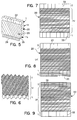
- FIG. 5 A further embodiment is shown in FIG. 5, wherein sheets 20 have the same vertical corrugations 22 in top region T; but, however, have reduced cross section corrugations 26 in base region L. More specifically, corrugations 26 are smaller in height than the corrugations found in bulk region U. Again, this difference in geometry recognizes the needs of the different regions of the packing section to accomplish transition and pressure reduction.
- surface texturing is to be understood as denoting any roughening, slitting, stamping and/or impressing of the sheet surface.
- Examples of surface texturing include, but are not limited to, grooving ("fluting"), impression of a pattern, for example, a herringbone or waffle pattern, or small deformed slits.
- fluting can be found in U.S. Patent No. 4,296,050, the disclosure of which is incorporated herein by reference. This patent discloses fine fluting in the form of grooves. The fine fluting results in spreading of liquid over the sheet surfaces as a result of capillary action.
- a further embodiment of the present invention is shown. More specifically, in this embodiment, a base region L of a sheet 20 is shown, wherein the base region L does not have the surface texturing shown in the bulk region U and the top region T.
- the embodiment shown in FIG. 6 discloses the surface texturing in region U and region T as the fine fluting of a packing sheet. The fine fluting extends generally horizontally and results in the spreading of liquid across the face of the sheet. Although the "surface texturing" shown is fine fluting, any other surface texturing could also be used.
- the base region L there may not be a need to have the liquid move across the packing, but instead to have the liquid move quickly off the packing sheet to the packing section below.
- top region T can also be void of surface texturing to accomplish the desired performance characteristics of the column. Therefore, a sheet is contemplated where both top region T and base region L, or only base region L or only top region T is devoid of surface texturing.
- a sheet 20 is shown having a bulk region U with fine flutings extending generally horizontal to the axis of the column.
- Top region T and bottom region L each have vertical corrugations 22.
- top region T and base region L do not have any surface texturing.
- top region T while having vertical corrugations 22, does not have fine fluting.
- base region L does have fine fluting in addition to vertical corrugations 22.
- FIG. 9 is a further variation of FIGS. 7 and 8, wherein top region T has fine fluting and vertical corrugations 22 while bottom region L does not have fine fluting, but does have vertical corrugations 22.
- fine fluting has been shown extending generally horizontal to the axis of the column. As is apparent, any other surface texturing could be used.
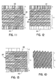
- top region T and base region L of a sheet 20 each have vertical corrugations 22. Additionally, each of top region T and base region L have generally vertical fine fluting, as opposed to the generally horizontal fine fluting found in base region U.
- a sheet 20 includes top region T and base region L with vertical corrugations 22. Additionally, top region T has generally vertical fine fluting, bulk region U has generally horizontal fine fluting, and base region L has no fine fluting at all.
- top region T and base region L have vertical corrugations 22 but wherein top region T has no fine fluting, bulk region U has generally horizontal fine fluting, and bottom region L has generally vertical fine fluting.
- any fluting that extends at a steeper angle than the generally horizontal fluting could be used to possibly enhance the performance characteristics of the column.
- the generally horizontal fine fluting in bulk region U could be any other suitable surface texturing.
- top region T and bottom region L can be utilized in top region T and bottom region L, with the different geometries disclosed in U.S. Patent No. 5,632,934.
- any of the generally horizontal fine fluting and vertical fluting combinations disclosed above could be utilized in conjunction with the flat sheet 24 geometries, or reduced corrugation height geometry 26 discussed above.
- a sheet 20 in addition to surface texturing, could have a plurality of discrete apertures disposed throughout. Such apertures could be as disclosed in U.S. Patent No. 4,296,050. If such apertures are disposed in a sheet 20, it may be desirable to have top region T or bottom region L, or both, be devoid of such apertures in addition to being devoid of surface texturing.
- the present invention may be used in any distillation, absorption, or stripping process, which may employ structured packing.
- structured packing include, oil fractionations, hydrocarbon separations, alcohol distillations, and cryogenic rectification such as cryogenic air separation systems.
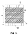
- sheet 20 is shown as having a bulk region U with fine fluting extending generally horizontal to the axis of the column.
- Bulk region U also has apertures 28 disposed throughout.
- Top region T and bottom region L each have vertical corrugations 22.
- top region T and base region L do not have any surface texturing, nor do they have any apertures 28.
- the surfaces of top region T and base region L are smooth.
Landscapes
- Chemical & Material Sciences (AREA)
- Chemical Kinetics & Catalysis (AREA)
- Organic Chemistry (AREA)
- Physics & Mathematics (AREA)
- Thermal Sciences (AREA)
- Dispersion Chemistry (AREA)
- Physical Or Chemical Processes And Apparatus (AREA)
- Vaporization, Distillation, Condensation, Sublimation, And Cold Traps (AREA)
- Separation By Low-Temperature Treatments (AREA)
- Revetment (AREA)
Applications Claiming Priority (2)
| Application Number | Priority Date | Filing Date | Title |
|---|---|---|---|
| US726586 | 1991-07-08 | ||
| US09/726,586 US6478290B2 (en) | 1999-12-09 | 2000-12-01 | Packing for mass transfer column |
Publications (1)
| Publication Number | Publication Date |
|---|---|
| EP1210977A1 true EP1210977A1 (fr) | 2002-06-05 |
Family
ID=24919210
Family Applications (1)
| Application Number | Title | Priority Date | Filing Date |
|---|---|---|---|
| EP01128639A Withdrawn EP1210977A1 (fr) | 2000-12-01 | 2001-11-30 | Garnissage pour de colonne d'échange de chaleur |
Country Status (8)
| Country | Link |
|---|---|
| US (3) | US6478290B2 (fr) |
| EP (1) | EP1210977A1 (fr) |
| JP (1) | JP4408190B2 (fr) |
| KR (1) | KR20020043176A (fr) |
| CN (1) | CN1244399C (fr) |
| BR (1) | BR0105764A (fr) |
| CA (1) | CA2364225C (fr) |
| MX (1) | MXPA01012370A (fr) |
Cited By (2)
| Publication number | Priority date | Publication date | Assignee | Title |
|---|---|---|---|---|
| EP1195563A3 (fr) * | 2000-10-06 | 2003-04-02 | Praxair Technology, Inc. | Système de garnissage structuré permettant une hauteur réduite de colonne de distillation |
| US10376860B2 (en) | 2013-06-07 | 2019-08-13 | Sulzer Chemtech Ag | Packing layer for structured packing |
Families Citing this family (31)
| Publication number | Priority date | Publication date | Assignee | Title |
|---|---|---|---|---|
| US6478290B2 (en) * | 1999-12-09 | 2002-11-12 | Praxair Technology, Inc. | Packing for mass transfer column |
| FR2806325B1 (fr) * | 2000-03-17 | 2002-10-18 | Air Liquide | Module de garnissage, son procede de fabrication, et appareil de traitement de fluide(s) comportant un garnissage correspondant |
| DE10124386A1 (de) * | 2001-05-18 | 2002-11-28 | Basf Ag | Verfahren zur Destillation oder Reaktivdestillation eines Gemisches, das mindestens eine toxische Komponente enthält |
| US20030116871A1 (en) * | 2001-12-21 | 2003-06-26 | Steven Ringo | Structured packing |
| RU2232632C1 (ru) * | 2003-01-30 | 2004-07-20 | Саратовское акционерное производственно-коммерческое открытое общество "Нефтемаш" - САПКОН | Регулярная насадка |
| DE10337073A1 (de) * | 2003-08-12 | 2005-03-10 | Linde Ag | Verfahren und Vorrichtung zur Herstellung einer geordneten Packung |
| DE10343650A1 (de) * | 2003-09-20 | 2005-04-14 | Julius Montz Gmbh | Geordnete Packung für Wärme- und Stoffaustausch |
| FR2871073B1 (fr) * | 2004-06-04 | 2007-04-13 | Air Liquide | Bande pour module de garnissage ondule-croise, procede de fabrication et module de garnissage ondule-croise correspondants |
| FR2871074B1 (fr) * | 2004-06-04 | 2007-03-16 | Air Liquide | Bande pour module de garnissage, module de garnissage et installation de distillation correspondants |
| US7267329B2 (en) * | 2005-07-27 | 2007-09-11 | Air Products And Chemicals, Inc. | Alternating conventional and high capacity packing within the same section of an exchange column |
| DE102006003317B4 (de) | 2006-01-23 | 2008-10-02 | Alstom Technology Ltd. | Rohrbündel-Wärmetauscher |
| DE102006005112A1 (de) * | 2006-02-04 | 2007-08-09 | Hewitech Gmbh & Co. Kg | Kunststofflage für ein Einbauelement zum Einbau in einem Riesenkühler, insbesondere Kühlturm zu Kühlzwecken oder zum Einbau ins Erdreich zu Drainagezwecken |
| FR2911391A1 (fr) * | 2007-01-16 | 2008-07-18 | Air Liquide | Procede de separation utilisant une colonne a garnissage structure ondule-croise pour la separation d'un melange de gaz et colonne adaptee a etre utilisee pour le procede |
| CN101952005B (zh) * | 2007-07-09 | 2015-02-25 | 查特工业公司 | 板翼片流体处理装置 |
| FR2929134B1 (fr) * | 2008-03-28 | 2010-12-31 | Air Liquide | Procede de fabrication d'un garnissage ondule-croise |
| US9557119B2 (en) | 2009-05-08 | 2017-01-31 | Arvos Inc. | Heat transfer sheet for rotary regenerative heat exchanger |
| FR2947188A1 (fr) * | 2009-06-24 | 2010-12-31 | Air Liquide | Bande pour module de garnissage, module de garnissage et installation de distillation correspondants |
| US20110310697A1 (en) * | 2010-06-22 | 2011-12-22 | Sebastian Hirschberg | Dust mixing device |
| US20120049392A1 (en) * | 2010-08-25 | 2012-03-01 | Carlos Jose Trompiz | Structured Packing with Extended Contact Area |
| US8985559B2 (en) * | 2012-01-03 | 2015-03-24 | Evapco, Inc. | Heat exchanger plate and a fill pack of heat exchanger plates |
| US9200853B2 (en) | 2012-08-23 | 2015-12-01 | Arvos Technology Limited | Heat transfer assembly for rotary regenerative preheater |
| FR2996148B1 (fr) * | 2012-10-03 | 2015-11-06 | Euroslot Kdss France | Element de garnissage structure pour colonne de mise en contact de fluides |
| US9295925B2 (en) | 2012-12-11 | 2016-03-29 | Praxair Technology, Inc. | Structured packing and method |
| US10175006B2 (en) | 2013-11-25 | 2019-01-08 | Arvos Ljungstrom Llc | Heat transfer elements for a closed channel rotary regenerative air preheater |
| US9956540B1 (en) * | 2015-03-31 | 2018-05-01 | Gtc Technology Us Llc | Structured packing with enhanced fluid-flow interface |
| ITUB20152873A1 (it) * | 2015-08-05 | 2017-02-05 | Baretti Mefe S R L | Impaccamento strutturato ad alta efficienza e capacita? per colonne di distillazione. |
| US10094626B2 (en) | 2015-10-07 | 2018-10-09 | Arvos Ljungstrom Llc | Alternating notch configuration for spacing heat transfer sheets |
| WO2019135139A1 (fr) * | 2018-01-08 | 2019-07-11 | Koch-Glitsch, Lp | Module de garnissage structuré destiné à être utilisé dans une colonne de transfert de masse et procédé d'assemblage |
| DE202018102787U1 (de) | 2018-05-18 | 2019-08-22 | Cts Cooling Tower Solutions Gmbh | Packung für eine Wärme- und/oder Stoffübertragung |
| JP2021142459A (ja) * | 2020-03-10 | 2021-09-24 | 大陽日酸株式会社 | 充填物、及び空気分離装置 |
| US20230271103A1 (en) | 2020-07-17 | 2023-08-31 | Koch-Glitsch, Lp | Process control systems with simulator for use with a mass transfer column |
Citations (7)
| Publication number | Priority date | Publication date | Assignee | Title |
|---|---|---|---|---|
| DE1302032B (de) * | 1964-07-10 | 1969-10-16 | Munters Carl Georg | Fluessigkeitsverteiler fuer einen aus lotrechten Rieselplatten bestehenden Kontaktkoerper |
| US4186159A (en) * | 1977-05-12 | 1980-01-29 | Sulzer Brothers Limited | Packing element of foil-like material for an exchange column |
| US5124087A (en) * | 1990-10-04 | 1992-06-23 | Evapco International, Inc. | Gas and liquid contact body |
| DE4122369C1 (en) * | 1991-07-05 | 1992-10-22 | Rainer Richter Gmbh, 5439 Hof, De | Packaging used for heat and mass transfer between liq. and gas - consists of corrugated or folded foil, plate or mat-like packaging elements in zones, in which profiles are inclined to longitudinal axis, etc. |
| EP0745825A2 (fr) * | 1995-05-31 | 1996-12-04 | BDAG Balcke-Dürr Aktiengesellschaft | Elément de ruisselement |
| EP0858830A1 (fr) * | 1997-02-13 | 1998-08-19 | Praxair Technology, Inc. | Garnissage ondulé à capacité augmenté et avec échange de matière à haut rendement |
| EP0992282A1 (fr) * | 1998-10-02 | 2000-04-12 | Praxair Technology, Inc. | Système de rectification cryogénique avec garnissage de haute résistance et capacité |
Family Cites Families (13)
| Publication number | Priority date | Publication date | Assignee | Title |
|---|---|---|---|---|
| NL281630A (fr) * | 1963-03-04 | |||
| CH617357A5 (fr) | 1977-05-12 | 1980-05-30 | Sulzer Ag | |
| DE8904345U1 (de) * | 1989-04-07 | 1989-05-18 | Streng, Andreas, Dipl.-Ing., 5210 Troisdorf | Wärme- und Stoffübertrager |
| US5147583A (en) * | 1990-12-20 | 1992-09-15 | The Marley Cooling Tower Company | Non-clogging film fill assembly for counterflow water cooling tower |
| ATA166091A (de) * | 1991-08-23 | 1996-02-15 | Faigle Heinz Kg | Füllkörper |
| US5217788A (en) * | 1992-05-11 | 1993-06-08 | Brentwood Industries | Corrugated sheet assembly |
| US5320651A (en) * | 1993-06-28 | 1994-06-14 | Munters Corporation | Cross-flow film fill media with intergral drift eliminator |
| CN1091646C (zh) | 1994-10-04 | 2002-10-02 | 普莱克斯技术有限公司 | 用于精炼系统的高容量结构填料 |
| GB9522086D0 (en) * | 1995-10-31 | 1996-01-03 | Ici Plc | Fluid-fluid contacting apparatus |
| DE19844075A1 (de) * | 1998-09-25 | 2000-03-30 | Man Nutzfahrzeuge Ag | Kompakter Kreuzkanalmischer |
| US5921109A (en) | 1998-10-21 | 1999-07-13 | Praxair Technology, Inc. | Method for operating a cryogenic rectification column |
| US6478290B2 (en) * | 1999-12-09 | 2002-11-12 | Praxair Technology, Inc. | Packing for mass transfer column |
| US6212907B1 (en) * | 2000-02-23 | 2001-04-10 | Praxair Technology, Inc. | Method for operating a cryogenic rectification column |
-
2000
- 2000-12-01 US US09/726,586 patent/US6478290B2/en not_active Expired - Lifetime
-
2001
- 2001-11-30 EP EP01128639A patent/EP1210977A1/fr not_active Withdrawn
- 2001-11-30 JP JP2001366001A patent/JP4408190B2/ja not_active Expired - Fee Related
- 2001-11-30 MX MXPA01012370A patent/MXPA01012370A/es active IP Right Grant
- 2001-11-30 KR KR1020010075258A patent/KR20020043176A/ko not_active Ceased
- 2001-11-30 BR BR0105764-2A patent/BR0105764A/pt not_active Application Discontinuation
- 2001-11-30 CN CNB01142494XA patent/CN1244399C/zh not_active Expired - Fee Related
- 2001-11-30 CA CA002364225A patent/CA2364225C/fr not_active Expired - Lifetime
-
2002
- 2002-07-18 US US10/197,471 patent/US6578829B2/en not_active Expired - Lifetime
- 2002-07-25 US US10/201,999 patent/US20030006511A1/en not_active Abandoned
Patent Citations (7)
| Publication number | Priority date | Publication date | Assignee | Title |
|---|---|---|---|---|
| DE1302032B (de) * | 1964-07-10 | 1969-10-16 | Munters Carl Georg | Fluessigkeitsverteiler fuer einen aus lotrechten Rieselplatten bestehenden Kontaktkoerper |
| US4186159A (en) * | 1977-05-12 | 1980-01-29 | Sulzer Brothers Limited | Packing element of foil-like material for an exchange column |
| US5124087A (en) * | 1990-10-04 | 1992-06-23 | Evapco International, Inc. | Gas and liquid contact body |
| DE4122369C1 (en) * | 1991-07-05 | 1992-10-22 | Rainer Richter Gmbh, 5439 Hof, De | Packaging used for heat and mass transfer between liq. and gas - consists of corrugated or folded foil, plate or mat-like packaging elements in zones, in which profiles are inclined to longitudinal axis, etc. |
| EP0745825A2 (fr) * | 1995-05-31 | 1996-12-04 | BDAG Balcke-Dürr Aktiengesellschaft | Elément de ruisselement |
| EP0858830A1 (fr) * | 1997-02-13 | 1998-08-19 | Praxair Technology, Inc. | Garnissage ondulé à capacité augmenté et avec échange de matière à haut rendement |
| EP0992282A1 (fr) * | 1998-10-02 | 2000-04-12 | Praxair Technology, Inc. | Système de rectification cryogénique avec garnissage de haute résistance et capacité |
Cited By (2)
| Publication number | Priority date | Publication date | Assignee | Title |
|---|---|---|---|---|
| EP1195563A3 (fr) * | 2000-10-06 | 2003-04-02 | Praxair Technology, Inc. | Système de garnissage structuré permettant une hauteur réduite de colonne de distillation |
| US10376860B2 (en) | 2013-06-07 | 2019-08-13 | Sulzer Chemtech Ag | Packing layer for structured packing |
Also Published As
| Publication number | Publication date |
|---|---|
| CN1244399C (zh) | 2006-03-08 |
| US20020190402A1 (en) | 2002-12-19 |
| US20030006511A1 (en) | 2003-01-09 |
| KR20020043176A (ko) | 2002-06-08 |
| JP4408190B2 (ja) | 2010-02-03 |
| BR0105764A (pt) | 2002-08-27 |
| MXPA01012370A (es) | 2002-07-09 |
| CA2364225C (fr) | 2005-03-29 |
| CN1358565A (zh) | 2002-07-17 |
| US6478290B2 (en) | 2002-11-12 |
| JP2002204952A (ja) | 2002-07-23 |
| CA2364225A1 (fr) | 2002-06-01 |
| US6578829B2 (en) | 2003-06-17 |
| US20010040303A1 (en) | 2001-11-15 |
Similar Documents
| Publication | Publication Date | Title |
|---|---|---|
| US6478290B2 (en) | Packing for mass transfer column | |
| JP7583085B2 (ja) | 物質移動カラムのための構造化充填モジュール | |
| US6206349B1 (en) | Fluid-fluid contacting apparatus | |
| CA2159752C (fr) | Garniture structuree a capacite amelioree pour systemes de rectification | |
| US7025339B2 (en) | Structured packing with increased capacity | |
| EP0858830A1 (fr) | Garnissage ondulé à capacité augmenté et avec échange de matière à haut rendement | |
| US6991222B2 (en) | Structured packing with increased capacity | |
| EP1752214A1 (fr) | Elément de remplissage pour colonne d'échange | |
| KR20250029166A (ko) | 구조화된 패킹 | |
| KR100398813B1 (ko) | 증류장치용 타워인터널의 구조 패킹 | |
| CN1318130C (zh) | 具有不对称卷曲形状的规整填料 | |
| KR200257200Y1 (ko) | 증류장치용 타워인터널의 구조 패킹 | |
| JPH08168670A (ja) | 充填物 |
Legal Events
| Date | Code | Title | Description |
|---|---|---|---|
| PUAI | Public reference made under article 153(3) epc to a published international application that has entered the european phase |
Free format text: ORIGINAL CODE: 0009012 |
|
| AK | Designated contracting states |
Kind code of ref document: A1 Designated state(s): AT BE CH CY DE DK ES FI FR GB GR IE IT LI LU MC NL PT SE TR |
|
| AX | Request for extension of the european patent |
Free format text: AL;LT;LV;MK;RO;SI |
|
| 17P | Request for examination filed |
Effective date: 20020628 |
|
| 17Q | First examination report despatched |
Effective date: 20020920 |
|
| AKX | Designation fees paid |
Designated state(s): DE ES FR GB IT NL |
|
| STAA | Information on the status of an ep patent application or granted ep patent |
Free format text: STATUS: THE APPLICATION IS DEEMED TO BE WITHDRAWN |
|
| 18D | Application deemed to be withdrawn |
Effective date: 20150602 |