EP1211134A2 - Porte-charges - Google Patents
Porte-charges Download PDFInfo
- Publication number
- EP1211134A2 EP1211134A2 EP01204667A EP01204667A EP1211134A2 EP 1211134 A2 EP1211134 A2 EP 1211134A2 EP 01204667 A EP01204667 A EP 01204667A EP 01204667 A EP01204667 A EP 01204667A EP 1211134 A2 EP1211134 A2 EP 1211134A2
- Authority
- EP
- European Patent Office
- Prior art keywords
- construction
- vehicle
- load
- rail
- rear side
- Prior art date
- Legal status (The legal status is an assumption and is not a legal conclusion. Google has not performed a legal analysis and makes no representation as to the accuracy of the status listed.)
- Withdrawn
Links
Images


Classifications
-
- B—PERFORMING OPERATIONS; TRANSPORTING
- B60—VEHICLES IN GENERAL
- B60R—VEHICLES, VEHICLE FITTINGS, OR VEHICLE PARTS, NOT OTHERWISE PROVIDED FOR
- B60R9/00—Supplementary fittings on vehicle exterior for carrying loads, e.g. luggage, sports gear or the like
- B60R9/06—Supplementary fittings on vehicle exterior for carrying loads, e.g. luggage, sports gear or the like at vehicle front or rear
-
- B—PERFORMING OPERATIONS; TRANSPORTING
- B60—VEHICLES IN GENERAL
- B60R—VEHICLES, VEHICLE FITTINGS, OR VEHICLE PARTS, NOT OTHERWISE PROVIDED FOR
- B60R9/00—Supplementary fittings on vehicle exterior for carrying loads, e.g. luggage, sports gear or the like
- B60R9/08—Supplementary fittings on vehicle exterior for carrying loads, e.g. luggage, sports gear or the like specially adapted for sports gear
- B60R9/10—Supplementary fittings on vehicle exterior for carrying loads, e.g. luggage, sports gear or the like specially adapted for sports gear for cycles
Definitions
- the present invention relates to an assembly of an intermediate construction that is designed for having attached to it a load accommodation construction for a load, in particular one or more bicycles, and an attachment device for securing the intermediate construction to the rear side of a motor vehicle, according to the preamble of claim 1.
- a load carrier provided with such an assembly is known, for example from US 3,891,132, US 5,094,373, US 5,544,799 and US 5,454,496.
- the intermediate construction of these known load carriers is composed of a stationary arm that can be fixed to the vehicle and a swivelling arm that is attached by way of the pivot assembly to the stationary arm in such a way that it can swivel.
- the stationary arm in this case extends along the rear side of the vehicle, in particular parallel to the rear bumper.
- a load accommodation construction can swivel between a transport position and a clear access position.
- the load accommodation construction, and the load that it is carrying In the transport position the load accommodation construction, and the load that it is carrying, is situated behind the vehicle. This is necessary when the vehicle is being driven, but has the disadvantage that in that transport position access to the rear side of the vehicle is impeded or even totally blocked by the load and/or the load accommodation construction.
- the laden or unladen load accommodation construction can be taken into the clear access position, in which the load accommodation construction is situated more or less laterally beside the vehicle - in the vicinity of the rear side of the vehicle - in an orientation turned approximately a quarter turn relative to the transport position. There is therefore clear access to the rear side of the vehicle, and the tailgate, the rear door(s) or the boot lid, for example, can be opened.
- a disadvantage of the known load carriers is that a large amount of space is needed behind the vehicle in question to take the (laden) load accommodation construction into the clear access position. At crowded locations, for example, such as cycling events, there is then a considerable risk of someone else parking his vehicle so close behind the vehicle with the load carrier that there is insufficient space for the swivelling movement. There is also a risk of the load or load accommodation construction hitting the vehicle parked behind it during the swivelling movement, which can lead to damage to that vehicle and the load. It will be clear that the same problems also play a role if little space is available behind the vehicle in a garage.
- the object of the present invention is to provide an assembly of an intermediate construction that is designed for having attached to it a load accommodation construction for a load, in particular one or more bicycles, and an attachment device for securing the intermediate construction to the rear side of a motor vehicle, which assembly can offer clear access to the rear side of the vehicle even if relatively little space is available behind the vehicle with the load carrier.
- the present invention achieves this object by providing an assembly according to the preamble of claim 1, which is characterized in that the intermediate construction permits a translation of the pivot assembly along the rear side of the motor vehicle. If the vehicle with a load accommodation construction has been parked in the transport position, a translation of the load accommodation construction in a substantially transverse direction to the longitudinal axis of the vehicle can first be carried out, by translation of the pivot assembly more or less parallel to the rear side of the vehicle.
- the swivelling movement of the load accommodation construction about the pivot axis can then be carried out, approximately through a quarter turn, so that the load accommodation construction and the load, if present, goes more or less beside the vehicle, in such a way that the rear side of the vehicle is accessible, for example in order to open the tailgate.
- the clear space required behind the vehicle is considerably less in the case of the solution according to the invention than in the case of the known solutions mentioned earlier.
- the intermediate construction comprises a telescopic arm, having a stationary arm part which can be fixed by way of the attachment device to the motor vehicle, and having a telescopically movable arm part, which may, if desired, be composed of several elements and is telescopically guided relative to the stationary arm part, and which is movable back and forth substantially parallel to the rear side of the vehicle, the pivot assembly being fitted on the telescopic arm part.
- the intermediate construction comprises an elongated rail
- the attachment device is designed to fix the rail to the vehicle, in such a way that the rail extends along the rear side of the motor vehicle until near one or both of the rear corners of the motor vehicle, the intermediate construction further comprising a sliding member, which is fitted in such a way that it can slide back and forth on the rail.
- the load accommodation construction in this case can be fitted detachably or otherwise on the sliding member by way of the pivot assembly.
- the pivot assembly prefferably to be disposed in a manner staggered laterally outwards relative to the guide means of the sliding member, preferably in such a way that the pivot axis is situated beyond the side of the vehicle, while the adjacent end of the rail is situated inwards relative to the corner of the vehicle. This ensures that the rail does not constitute a dangerous or awkward projection on the vehicle, in particular if the load carrier is not loaded.
- a load accommodation construction can advantageously be fitted on the additional towing ball.
- provision can be made for the additional towing ball to form part of the pivot assembly.
- the pivot assembly can further advantageously be partly or fully exchangeable for an additional towing ball.
- the intermediate construction forms a curved translation path for the pivot assembly, which path is situated in a substantially horizontal plane.
- the present invention also relates to a load carrier designed for mounting on the rear side of a motor vehicle.
- the load carrier comprises a load accommodation construction for the accommodation of a load, in particular for one or more bicycles, and an assembly of an intermediate construction and an attachment device according to one or more of claims 1 - 11.
- the load accommodation construction can be connected to the intermediate construction in a detachable or fixed manner.
- the present invention also relates to a load carrier according to claim 13, in which the possibility of connecting a trailer or the like to the additional towing ball without removing the intermediate construction is provided.
- This embodiment is advantageous, for example, in combination with the intermediate construction as disclosed in US 5,664,717, in the case of which the additional towing ball can then be used to fix an already known load accommodation construction, which is designed for direct attachment to the vehicle towing ball, to the intermediate construction.
- the invention further relates to a load carrier according to claim 14, in which the required electrical connection for lighting on the rear side of the load carrier can easily be achieved, preferably automatically.
- FIGs 1 and 2 the rear part of a motor vehicle 1, shown by way of example, can be seen, which motor vehicle has a rear bumper 2, here extending around the corners on the rear side of the vehicle, and has a tailgate 3 fitted on the body in such a way that it can swing about a hinge along the top side.
- a load carrier according to the invention is fitted on the rear side of the vehicle 1.
- the load carrier comprises a load accommodation construction 10, which is adapted to a particular type of load, in this example a construction 10 on which several bicycles can be placed. It will be clear that the construction 10 can also be designed in a totally different way, for example as shown in the publications mentioned earlier or as in EP 0,666,197.
- the load carrier further comprises an intermediate construction 20, to be explained in greater detail below, and an attachment device 30, which is designed for securing the intermediate construction 20 on the rear side of the vehicle.
- the attachment device 30 is designed for rigid attachment of the intermediate construction 20 to the towing hook 32, which projects from the centre of the rear of the vehicle and is provided with a towing ball 31.
- the attachment device 30 is designed in such a way that the intermediate construction 20 can be fixed immovably on the towing hook 32 in a play-free manner, for example as shown in EP 0,666,197 or EP 0,943,495. If desired, provision may be made for an additional clamping construction, which can be fixed with one or more bolts, and clamps around the bar of the towing hook 32 below the towing ball 31.
- the load accommodation construction 10 is connected by way of a pivot assembly to the intermediate construction 20, which pivot assembly forms a vertical pivot axis 40.
- the load accommodation construction 10 is situated in a transport position, in other words behind the vehicle 1, with the bicycles (not shown) being disposed transversely behind the vehicle. In this position the vehicle can be driven. In the transport position the load accommodation construction 10 blocks the access to the rear side of the vehicle, certainly if one or more bicycles have been placed on it. In particular, the tailgate 3 cannot be opened.
- the intermediate construction 20 in this example comprises an elongated stable rail 21, preferably made of steel, which can be fixed firmly by means of the attachment device 30 to the towing hook 32.
- the rail 21 runs substantially parallel to the rear bumper 2, one end 22 of the rail 21 being situated near a corner of the rear side of the vehicle.
- the end 22 concerned is situated a distance staggered inwards relative to the side of the vehicle. Viewed from the attachment 30 towards the other end 23, the rail 21 is shorter.
- the rail 21 is a straight rail, but provision can also be made for the rail 21 to form a curved translation path for sliding member 25.
- the intermediate construction 20 further comprises a sliding member 25, which is mounted on the rail 21 in such a way that it can be slid back and forth by way of guide means.
- the load accommodation construction 10 is fitted on the sliding member 25 by way of the pivot assembly with pivot axis 40.
- the load carrier can be provided with locking means, for example a manually operable locking pin, for locking the position of the sliding member 25 relative to the rail 21 in the transport position of the load accommodation construction 10.
- the locking means then serve to prevent undesired movement of the load accommodation construction 10 during driving, and the locking means can also serve to eliminate any play that there might be between the rail 21 and the guide means, with the result that undesired vibrations are prevented.
- the guide means can comprise one or more roller elements 26 fitted on the sliding member 25, for providing a roller bearing relative to the rail 21.
- the position of one or more of the roller elements 26 is preferably adjustable for play-free guidance of the sliding member 25 relative to the rail 21, for example with an eccentric mechanism.
- the sliding element 25 can be mounted on sliding bearings, for example with plastic sliding parts.
- the pivot axis 40 is disposed in a position staggered laterally outwards relative to the guide means 26 of the sliding member 25, in such a way that the pivot axis 40 projects outwards beyond the end 22 of the rail 21 when the sliding member 25 is situated near the end 22.
- the pivot axis 40 is then preferably situated even further outwards than the side of the vehicle.
- the construction makes it possible to keep the distance between the pivot axis 40 and the centre of gravity of the (laden) construction 10 short - which is advantageous for the loading of the pivot assembly - and also to ensure that the end 22 of the rail 21 lies relatively far inwards, so that end 22 of the rail 21 does not become caught up in anything or cause damage when the vehicle is being driven.
- operable locking means can be provided near the pivot assembly, which locking means block the swinging movement of the construction 10 about the pivot axis 40, so that an accidental swing, for example when the bicycles are being placed in position or being removed, is prevented.
- the rail 21 runs towards the other corner of the vehicle, or that the rail 21 extends towards both corners. It will further be clear that the rail 21 can be composed of several rail elements, for example two tubular sections lying one above the other, between which the rollers 26 are placed.
- the towing hook 32 is of the type that comprises a towing hook part fitted immovably on the vehicle and a towing hook part with the towing ball 31 that can be fitted detachably on the first part.
- the securing device 30 it is conceivable for the securing device 30 to be designed in such a way that the load carrier can be fixed directly to the towing hook part of the towing hook 32 fitted immovably on the vehicle, without making use of the ball 31.
- the invention provides a variant of an embodiment (not shown) in which the sliding member 25 is provided with a plug element, and a socket element that can be connected to the plug element is provided on the rail 21 and/or the attachment device 30, which socket element in turn can be connected to the electrical system of the vehicle, in such a way that the plug element and the socket element can be connected in the transport position of the load accommodation construction, preferably by automatic connection if the load accommodation construction is being taken into the transport position.
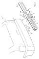
- Figure 3 shows the rear side of the vehicle 1, and at a distance from it the relevant part of the load carrier.
- a metal rail 50 with a substantially C-shaped cross section, in which the centre web of the rail 50 is directed vertically, the centre web being in the form of a tubular section.
- the legs of the C-shaped rail 50 form guide grooves, situated above one another, for the top side and the bottom side of a sliding member 60 to be described in greater detail.
- An attachment device 70 is fitted on the rail 50, in order to fix the rail 50 on the towing hook 32.
- the assembly 70 comprises a part into which the ball 31 fits, with a locking plate engaging below the ball 31 and having a keyhole opening and a locking bolt 71 that presses on the top of the ball 31.
- the assembly 70 further comprises a clamp 72, which below the ball is fixed around the bar of the towing hook.
- the sliding member 60 comprises a guide part 61, which is provided with guide means fitting into the C-shaped cross section of the rail, in this example said guide means being rollers 62 and adjusting roller 63, which is adjustable with an eccentric.
- the sliding member 60 further comprises a pivoting part 65, which is attached by way of pivot 66 to the guide part 61, and which is designed for attachment of the load accommodation construction, detachably or otherwise.
- a pivoting part 65 which is attached by way of pivot 66 to the guide part 61, and which is designed for attachment of the load accommodation construction, detachably or otherwise.
- projection 67 to which a load accommodation construction can be attached, can be seen.
- pivoting part 65 of the sliding member 60 also fits in a slidable manner in the C-shaped cross section of the rail 50, in such a way that in the transport position the pivoting part 65 is situated in the rail 50, and in such a way that in the clear access position the pivoting part 65 projects beyond the rail 50, while the guide part 61 is situated near the corresponding end of the rail 50, and can be turned approximately a quarter turn relative to the rail 50.
- the pivoting part 65 may, if desired, be provided with sliding parts for the sliding guidance relative to the rail 50.
- An additional towing ball can be fitted on the projection 67, so that a known load carrier with integral towing hook attachment device can be attached to the intermediate construction shown.
- Said additional towing ball is preferably fitted at substantially the same height as the vehicle towing ball.
Landscapes
- Engineering & Computer Science (AREA)
- Mechanical Engineering (AREA)
- Fittings On The Vehicle Exterior For Carrying Loads, And Devices For Holding Or Mounting Articles (AREA)
Applications Claiming Priority (2)
| Application Number | Priority Date | Filing Date | Title |
|---|---|---|---|
| NL1016761A NL1016761C1 (nl) | 2000-11-30 | 2000-11-30 | Aan de achterzijde van een motorvoertuig monteerbare ladingdrager, in het bijzonder voor een of meer fietsen. |
| NL1016761 | 2000-11-30 |
Publications (2)
| Publication Number | Publication Date |
|---|---|
| EP1211134A2 true EP1211134A2 (fr) | 2002-06-05 |
| EP1211134A3 EP1211134A3 (fr) | 2002-08-14 |
Family
ID=19772503
Family Applications (1)
| Application Number | Title | Priority Date | Filing Date |
|---|---|---|---|
| EP01204667A Withdrawn EP1211134A3 (fr) | 2000-11-30 | 2001-11-30 | Porte-charges |
Country Status (2)
| Country | Link |
|---|---|
| EP (1) | EP1211134A3 (fr) |
| NL (1) | NL1016761C1 (fr) |
Cited By (11)
| Publication number | Priority date | Publication date | Assignee | Title |
|---|---|---|---|---|
| DE102005039254A1 (de) * | 2005-08-19 | 2007-02-22 | Inter Agilis Handelsgesellschaft M.B.H. | Transportvorrichtung am Heck eines Kastenwagens |
| NL1037475C2 (nl) * | 2009-11-17 | 2011-05-19 | Kees Vogel | Trekhaakconstructie en voertuig voorzien van een dergelijke trekhaakconstructie. |
| EP2460692A2 (fr) * | 2010-12-01 | 2012-06-06 | WESTFALIA - Automotive GmbH | Support de charge doté d'un dispositif de fixation entraîné |
| EP1868847B2 (fr) † | 2005-04-15 | 2013-04-03 | BOS GmbH & Co. KG | Dispositif pour ensemble porteur de charge fixe a un vehicule |
| DE202012103182U1 (de) | 2012-08-22 | 2013-12-02 | Al-Ko Kober Se | Lastenträger |
| DE102013108126B3 (de) * | 2013-07-30 | 2014-10-30 | Roman Buck | Staubox-Vorrichtung für Kraftfahrzeuge |
| DE102014019274A1 (de) * | 2014-12-23 | 2016-06-23 | Bicyclejack Ug (Haftungsbeschränkt) | Hebevorrichtung für mindestens ein Zweirad |
| EP2364880B1 (fr) | 2007-03-23 | 2018-08-15 | WESTFALIA - Automotive GmbH | Support de charge pour un véhicule automobile |
| EP3725593A1 (fr) * | 2019-04-17 | 2020-10-21 | Dieter Melder | Dispositif de support |
| EP3771597A3 (fr) * | 2019-08-02 | 2021-03-10 | Dieter Keibach | Adaptateur de porte-charge et porte-charge comprenant un tel adaptateur de porte-charge |
| EP4086118A1 (fr) | 2021-04-29 | 2022-11-09 | Karl Wagner | Dispositif de réception d'un porte-bicyclette |
Family Cites Families (3)
| Publication number | Priority date | Publication date | Assignee | Title |
|---|---|---|---|---|
| US3529737A (en) * | 1967-06-27 | 1970-09-22 | Melwyn Daugherty | Motorcycle carrier for vehicles |
| US5518159A (en) * | 1994-09-02 | 1996-05-21 | Deguevara; Orlando | Article support rack |
| FR2769880B1 (fr) * | 1997-10-17 | 2000-01-14 | Bernard Robert | Porte bicyclette transportable a l'arriere d'un vehicule |
-
2000
- 2000-11-30 NL NL1016761A patent/NL1016761C1/nl not_active IP Right Cessation
-
2001
- 2001-11-30 EP EP01204667A patent/EP1211134A3/fr not_active Withdrawn
Cited By (15)
| Publication number | Priority date | Publication date | Assignee | Title |
|---|---|---|---|---|
| EP1868847B2 (fr) † | 2005-04-15 | 2013-04-03 | BOS GmbH & Co. KG | Dispositif pour ensemble porteur de charge fixe a un vehicule |
| DE102005039254A1 (de) * | 2005-08-19 | 2007-02-22 | Inter Agilis Handelsgesellschaft M.B.H. | Transportvorrichtung am Heck eines Kastenwagens |
| EP2364880B1 (fr) | 2007-03-23 | 2018-08-15 | WESTFALIA - Automotive GmbH | Support de charge pour un véhicule automobile |
| NL1037475C2 (nl) * | 2009-11-17 | 2011-05-19 | Kees Vogel | Trekhaakconstructie en voertuig voorzien van een dergelijke trekhaakconstructie. |
| EP2460692A2 (fr) * | 2010-12-01 | 2012-06-06 | WESTFALIA - Automotive GmbH | Support de charge doté d'un dispositif de fixation entraîné |
| DE202012103182U1 (de) | 2012-08-22 | 2013-12-02 | Al-Ko Kober Se | Lastenträger |
| DE102013108126B3 (de) * | 2013-07-30 | 2014-10-30 | Roman Buck | Staubox-Vorrichtung für Kraftfahrzeuge |
| DE102014110767B4 (de) * | 2013-07-30 | 2017-05-04 | Roman Buck | Lastenträger-Vorrichtung für Kraftfahrzeuge |
| DE102014019274A1 (de) * | 2014-12-23 | 2016-06-23 | Bicyclejack Ug (Haftungsbeschränkt) | Hebevorrichtung für mindestens ein Zweirad |
| DE102014019274B4 (de) | 2014-12-23 | 2019-12-19 | Bicyclejack Ug (Haftungsbeschränkt) | Hebevorrichtung für mindestens ein Zweirad |
| EP3725593A1 (fr) * | 2019-04-17 | 2020-10-21 | Dieter Melder | Dispositif de support |
| WO2020212035A1 (fr) * | 2019-04-17 | 2020-10-22 | Dieter Melder | Ensemble porte-bagages |
| US12162438B2 (en) | 2019-04-17 | 2024-12-10 | Dieter Melder | Support device |
| EP3771597A3 (fr) * | 2019-08-02 | 2021-03-10 | Dieter Keibach | Adaptateur de porte-charge et porte-charge comprenant un tel adaptateur de porte-charge |
| EP4086118A1 (fr) | 2021-04-29 | 2022-11-09 | Karl Wagner | Dispositif de réception d'un porte-bicyclette |
Also Published As
| Publication number | Publication date |
|---|---|
| NL1016761C1 (nl) | 2002-05-31 |
| EP1211134A3 (fr) | 2002-08-14 |
Similar Documents
| Publication | Publication Date | Title |
|---|---|---|
| US6682086B1 (en) | Step platform and ball hitch assembly | |
| US5544799A (en) | Swing away cargo carrier assembly | |
| CA3101262C (fr) | Porte-charge | |
| US10479284B1 (en) | Load-bearing system for supporting cargo from a vehicle | |
| US5738362A (en) | Rotating step for a trailer hitch | |
| US6123498A (en) | Pivoting vehicle rack | |
| US5038983A (en) | Vehicle cargo carrier attachment | |
| US6152341A (en) | Vehicle hitch mounted cargo carrier | |
| US7125062B2 (en) | Multi-functional cargo bed assembly | |
| CA1288456C (fr) | Combinaison de caisse et de plate-forme de vehicule visant a faciliter le chargement et le dechargement de marchandises | |
| US5685469A (en) | Swing-down carriers with top actuators | |
| US5560525A (en) | Load carrier | |
| US6183035B1 (en) | Tonneau cover and attachment assembly | |
| EP1095818B1 (fr) | Porte-bicyclette adapté au montage à l'intérieur d'un véhicule | |
| US5845832A (en) | Rear-mounted vehicle cargo carrier | |
| US5564773A (en) | Pickup truck bed cover | |
| US6338520B2 (en) | Tonneau cover and attachment assembly | |
| US5573161A (en) | Article carrier crossbar with split stanchion clamp | |
| EP1095820B1 (fr) | Porte-charges | |
| EP2848473B1 (fr) | Porte-charge pour le montage sur l'arrière d'un véhicule | |
| NL1016761C1 (nl) | Aan de achterzijde van een motorvoertuig monteerbare ladingdrager, in het bijzonder voor een of meer fietsen. | |
| CA2683267A1 (fr) | Dispositif de verrouillage de capot basculant | |
| US5641108A (en) | Bicycle and ski carrier for attachment to an automobile receiver hitch | |
| US6623025B2 (en) | Trailer hitch with trailer hitch accessory mounting assembly | |
| US6409065B1 (en) | Latching hitch mount carrier |
Legal Events
| Date | Code | Title | Description |
|---|---|---|---|
| PUAI | Public reference made under article 153(3) epc to a published international application that has entered the european phase |
Free format text: ORIGINAL CODE: 0009012 |
|
| AK | Designated contracting states |
Kind code of ref document: A2 Designated state(s): AT BE CH CY DE DK ES FI FR GB GR IE IT LI LU MC NL PT SE TR |
|
| AX | Request for extension of the european patent |
Free format text: AL;LT;LV;MK;RO;SI |
|
| PUAL | Search report despatched |
Free format text: ORIGINAL CODE: 0009013 |
|
| PUAF | Information related to the publication of a search report (a3 document) modified or deleted |
Free format text: ORIGINAL CODE: 0009199SEPU |
|
| RIC1 | Information provided on ipc code assigned before grant |
Free format text: 7B 60R 9/10 A, 7B 60R 9/06 B |
|
| AK | Designated contracting states |
Kind code of ref document: A3 Designated state(s): AT BE CH CY DE DK ES FI FR GB GR IE IT LI LU MC NL PT SE TR |
|
| AX | Request for extension of the european patent |
Free format text: AL;LT;LV;MK;RO;SI |
|
| D17D | Deferred search report published (deleted) | ||
| PUAL | Search report despatched |
Free format text: ORIGINAL CODE: 0009013 |
|
| AX | Request for extension of the european patent |
Free format text: AL;LT;LV;MK;RO;SI |
|
| 17P | Request for examination filed |
Effective date: 20030422 |
|
| AKX | Designation fees paid |
Designated state(s): AT BE CH CY DE DK ES FI FR GB GR IE IT LI LU MC NL PT SE TR |
|
| 17Q | First examination report despatched |
Effective date: 20060901 |
|
| GRAP | Despatch of communication of intention to grant a patent |
Free format text: ORIGINAL CODE: EPIDOSNIGR1 |
|
| STAA | Information on the status of an ep patent application or granted ep patent |
Free format text: STATUS: THE APPLICATION IS DEEMED TO BE WITHDRAWN |
|
| 18D | Application deemed to be withdrawn |
Effective date: 20081122 |