EP1211155B1 - Positionseinstellvorrichtung für Fahrzeuglenksäulen - Google Patents
Positionseinstellvorrichtung für Fahrzeuglenksäulen Download PDFInfo
- Publication number
- EP1211155B1 EP1211155B1 EP00311792A EP00311792A EP1211155B1 EP 1211155 B1 EP1211155 B1 EP 1211155B1 EP 00311792 A EP00311792 A EP 00311792A EP 00311792 A EP00311792 A EP 00311792A EP 1211155 B1 EP1211155 B1 EP 1211155B1
- Authority
- EP
- European Patent Office
- Prior art keywords
- steering column
- block
- column
- control lever
- tooth form
- Prior art date
- Legal status (The legal status is an assumption and is not a legal conclusion. Google has not performed a legal analysis and makes no representation as to the accuracy of the status listed.)
- Expired - Lifetime
Links
- 230000007246 mechanism Effects 0.000 claims description 7
- 230000002093 peripheral effect Effects 0.000 claims 1
- 230000008602 contraction Effects 0.000 description 3
- 238000004519 manufacturing process Methods 0.000 description 2
- 230000009977 dual effect Effects 0.000 description 1
Images


Classifications
-
- B—PERFORMING OPERATIONS; TRANSPORTING
- B62—LAND VEHICLES FOR TRAVELLING OTHERWISE THAN ON RAILS
- B62D—MOTOR VEHICLES; TRAILERS
- B62D1/00—Steering controls, i.e. means for initiating a change of direction of the vehicle
- B62D1/02—Steering controls, i.e. means for initiating a change of direction of the vehicle vehicle-mounted
- B62D1/16—Steering columns
- B62D1/18—Steering columns yieldable or adjustable, e.g. tiltable
- B62D1/184—Mechanisms for locking columns at selected positions
Definitions
- the present invention relates to a position setting device for vehicle steering columns.
- a steering column for vehide is installed within a cab so as to transmit rotatory force which is generated from a steering handle, to a steering wheel.
- Common practice is to provide the steering column with a telescopic device for controlling the axial extent of the column and a tilt device for controlling the direction of slant, thereby controlling the position of a steering handle according to the driver's requirements.
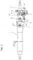
- FIG. 1 is a side view of a conventional position setting device for a vehide steering column.
- a steering column (1) is capable of longitudinal extension and contraction contracted due to the provision of a divided hollow shaft, including a steering shaft portion (2) at the upper end of the column which is provided with a universal joint (not illustrated) so as to allow articulation to vary the tilt of the steering column (1).
- Tilting is controlled by means of a tilt device (3) provided at one side of the steering column (1) so that the steering column can be fixed at a selected angle of articulation/tilt.
- This tilt device (3) is installed so as to pivot on a hinge (3b).
- Pulling of a tilt lever (3a) leads a cam face (3c) which is installed at the same shaft as hinge (3b), to release a rotatable member (3d) so that a set of normally-engaged teeth (3e) disengage.
- a tilt lever (3a) leads a cam face (3c) which is installed at the same shaft as hinge (3b), to release a rotatable member (3d) so that a set of normally-engaged teeth (3e) disengage.
- the driver releases the tilt lever (3a) the teeth remesh at the selected angle of tilt thereby fixing the steering column at that angle.
- Figure 2 is a cross-sectional view showing the telescopic action.
- a securing device (4) is provided at one side of the steering column (1).
- a locking lever (4a) installed at the exterior of a steering column (1) is turned, a screw (4b) connected thereto, is rotated.
- the locking lever By operating the locking lever so as to withdraw the screw (4b) from engagement with the shaft (2), the steering column (1) may be moved axially relative to the shaft (2) thereby allowing the column to be moved towards or away from the seated driver.
- the locking lever (4) is operated to re-engage the screw (4b) with the shaft (2).
- US Patent No. 5,820,163 discloses a tilting and telescoping steering column in which the telescoping and tilt locks are controlled by two separate levers.
- US Patent No. 5,351,572 discloses an adjusting drive for axially adjusting a steering column.
- An objective of the present invention is to provide a position setting device which is more convenient to use as well as being less complicated to manufacture and install.
- a vehicle steering column provided with mechanisms for adjustment of the column both axially and angularly, the column including a pair of telescopically related tubes; and characterised in that the mechanisms are controlled by a single control lever which is mounted for pivotal movement, and the axial adjustment mechanism comprising a lower block which is movable radially with respect to the steering column between a locking position, in which it couples the tubes together to prevent relative axial movement therebetween, and a releasing position in which the tubes are decoupled from each other to permit relative axial movement therebetween, and a taper block which engages the lower block through an inclined surface, whereby axial movement of the taper block is translated into radial movement of the lower block.
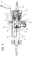
- a steering column (10) is designed to be lengthened or shortened by virtue of a telescopic arrangement comprising telescopically related tubes (11, 12) which can be released or locked against relative telescoping movement by means of a securing device (40).
- the tilt-controlling device (30) is pivotally mounted on a hinge (31) which extends transversely of the steering column (10).
- a cam face (not illustrated) connected to the inside of the hinge (31) and a rotation member which is turned by the cam face, are provided.
- a tooth form portion (33) - see Figure 4 - is provided on the one side of the rotation member. This rotation member and the tooth form portion (33) are connected to the cam face, thereby being engageable and disengageable way of a position control lever (32) extending to the exterior for access by the driver.
- the arrangement is such that operation of the lever (32) allows tilting of the upper shaft portion of the shaft (20) and release of the lever (32) locks the tilt mechanism in a selected tilted position.
- a restoring spring (35) connected to a mounting bracket (50) allows the position control lever (32) to be returned to its original position, after it has been operated and then released.
- a securing device (40) in the external upper portion of the steering column (10) is arranged for movement together with the tilt device (30) when the tilt device is operated by the rotation of the position control lever (32).
- the device (40) is installed in a manner that can be engaged and disengaged with the internal tube (11). That is to say, in a locking condition of the device (40), the tubes (11, 12) are locked together to prevent relative telescoping thereof and hence axial contraction or extension of the steering column. In a releasing condition of the device (40), the tubes (11, 12) are free to telescope with respect to one another thereby allowing the steering column to be extended or contracted by the user.
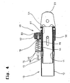
- a quadrangular through-aperture (51) is provided in a mounting element (50) which is coupled to the outer tube (12).
- the inner tube (11) is provided with a tooth form (13) for co-operation with a tooth form (61) provided on the radially inner end of a block (60) forming part of the device (40), the arrangement being such that the block (60) is movable radially inwardly and outwardly between an inner locking position in which the tooth forms (13, 60) are meshed, thereby preventing relative telescopic motion between the tube (11) and the mounting element (50) and hence between the tubes (11, 12), and an outer releasing position in which tooth forms (13, 61) are disengaged from to allow such telescopic action.
- the tooth form (61) may be of convexoconcave form.
- the block (60) forms part of a pair of blocks (60, 80), the upper block (80) being fixedly connected to the mounting element (50) by connectors (52).
- the blocks (60, 80) are channel shaped and are provided respectively with pairs of grooves (62, 82) in the side walls thereof (see Figure 5).
- the blocks (60, 80) receive a taper block (70) which is provided with upper and lower sets of protrusions (71) for reception in the grooves (62, 82) respectively of the blocks (60, 80) which are inclined so as to converge towards so that when the taper block (70) moves in one direction, the block (60) is drawn upwardly (or radially outwardly) towards the block (80) and, when moved in the opposite direction, the block (60) is displaced downwardly (radially inwardly) relative to the fixed block (80). In this manner, the block (60) can be moved between its locking and releasing positions as described above.
- Such movement of the taper block (70) is effected by means of the position control lever (32) through the agency of a Bowden cable (90).
- This cable (90) comprises an internal wire (91) which couples the lever (32) to the taper block (70), the outer sheath of the Bowden cable being arranged to extend between fixtures (16) and (15) associated respectively with the upper portion of shaft (20) and the main portion of the steering column (10).
- the Bowden cable 90 has a U-shaped configuration.
- lever (32) has a dual function. On the one hand, it allows tilting of the steering column assembly and in particular tilting of the upper portion of shaft (20) relative to the lower part of the steering column. At the same time, it disengages the tooth forms (13, 61) to allow axial extension and contraction of the upper portion of the shaft (20).
- a spring (95) is provided for biasing the taper block (70) to the position shown in Figure 4 so as to restore the taper block (70) to that position after release of the position control lever (32) following actuation thereof.
- the supporting spring (95) acts between the taper block (70) and fixture portion (15) and encircles the wire (91) as illustrated in Figure 4. In this way, the spring (95) ensures that, except when the lever (32) is rotated to disengage the tooth forms (13, 61) and also allow tilting, the block (60) is driven into its radially inner position in which the tooth form (61) meshes with the tooth form (13).
- the position setting device of vehicle steering column maintains the position of a controlled steering column (10) since, when the position control lever (32) is not operated, the tooth form portion of the tilt device (30) engages with the rotation member and the tooth form (61) of the lower block (60) engages with the tooth form (13) of the internal tube (11).
- a position setting device of a vehicle steering column has the advantage both the telescopic action and the titling action of the steering column may be controlled with the aid of a single control lever and, as a consequence, it is easy to manufacture, install and manipulate the steering column.
Landscapes
- Engineering & Computer Science (AREA)
- Chemical & Material Sciences (AREA)
- Combustion & Propulsion (AREA)
- Transportation (AREA)
- Mechanical Engineering (AREA)
- Steering Controls (AREA)
Claims (6)
- Fahrzeug-Lenksäule (10), die mit Mechanismen (30, 40) für die sowohl axiale als auch winkelmäßige Einstellung der Säule (10) versehen ist, welche Säule (10) ein Paar von teleskopisch in Beziehung stehenden Rohren (11, 12) enthält, dadurch gekennzeichnet, dass die Mechanismen (30, 40) durch einen einzelnen Steuerhebel (32) gesteuert werden, der für eine Schwenkbewegung gelagert ist, und der axiale Einstellmechanismus (40) einen unteren Block (60), der radial mit Bezug auf die Lenksäule (10) zwischen einer Verriegelungsposition, in der er die Rohe (11, 12) miteinander koppelt, um eine relative axiale Bewegung zwischen diesen zu verhindern, und einer Freigabeposition, in der die Rohre (11, 12) voneinander entkoppelt sind, um eine relative axiale Bewegung zwischen diesen zuzulassen, bewegbar ist, sowie einen konischen Block (70), der mit dem unteren Block (60) über eine geneigte Oberfläche (62) in Eingriff tritt, aufweist, wodurch eine axiale Bewegung des konischen Blocks (70) in eine radiale Bewegung des unteren Blocks (60) umgesetzt wird.
- Lenksäule nach Anspruch 1, bei der der konische Block (70) mit dem unteren Block (60) durch zumindest eine geneigte Führungsnut (62) und zumindest einen Führungsvorsprung (71), der in der Führungsnut (62) aufgenommen ist, gekoppelt ist.
- Lenksäule nach Anspruch 1 oder Anspruch 2, bei der der konische Block (70) mit dem Steuerhebel (32) durch einen Draht gekoppelt ist, der den konischen Block (70) als Antwort auf eine Bewegung des Steuerhebels (32) bewegt.
- Lenksäule nach Anspruch 3, bei der zwei Führungsnuten (62) und zwei Führungsvorsprünge (71) vorgesehen sind, wobei ein Führungsvorsprung innerhalb jeder Führungsnut (62) aufgenommen ist und die Führungsvorsprünge (71) zueinander symmetrisch sind.
- Lenksäule nach einem der vorhergehenden Ansprüche, bei der der untere Block (60) eine Zahnform (61) enthält, die in Eingriff mit einer Zahnform (13) ist, die an einer Umfangsfläche des inneren Rohres (11) vorgesehen ist.
- Lenksäule nach Anspruch 5, bei der die Zahnform (61) eine konvex-konkave Konfiguration hat.
Applications Claiming Priority (2)
| Application Number | Priority Date | Filing Date | Title |
|---|---|---|---|
| KR2000072269 | 2000-12-01 | ||
| KR10-2000-0072269A KR100377435B1 (ko) | 2000-12-01 | 2000-12-01 | 차량용 스티어링 컬럼의 위치조절장치 |
Publications (4)
| Publication Number | Publication Date |
|---|---|
| EP1211155A2 EP1211155A2 (de) | 2002-06-05 |
| EP1211155A3 EP1211155A3 (de) | 2003-04-23 |
| EP1211155B1 true EP1211155B1 (de) | 2006-03-01 |
| EP1211155B2 EP1211155B2 (de) | 2006-03-08 |
Family
ID=36129241
Family Applications (1)
| Application Number | Title | Priority Date | Filing Date |
|---|---|---|---|
| EP00311792A Expired - Lifetime EP1211155B2 (de) | 2000-12-01 | 2000-12-29 | Positionseinstellvorrichtung für Fahrzeuglenksäulen |
Country Status (5)
| Country | Link |
|---|---|
| US (1) | US6467367B2 (de) |
| EP (1) | EP1211155B2 (de) |
| JP (1) | JP3335996B2 (de) |
| KR (1) | KR100377435B1 (de) |
| DE (1) | DE60026261T2 (de) |
Families Citing this family (25)
| Publication number | Priority date | Publication date | Assignee | Title |
|---|---|---|---|---|
| DE10129165B4 (de) * | 2001-06-11 | 2004-02-05 | Dr.Ing.H.C. F. Porsche Ag | Verriegelungsvorrichtung für eine einstellbare Lenksäule |
| US6868750B2 (en) * | 2001-11-21 | 2005-03-22 | Hyundai Mobis Co., Ltd. | Telescopic device of steering column for vehicle |
| KR100488306B1 (ko) * | 2002-01-04 | 2005-05-11 | 현대모비스 주식회사 | 차량용 스티어링 컬럼의 텔레스코픽 장치 |
| US6653137B2 (en) * | 2001-12-03 | 2003-11-25 | Streck Laboratories Inc. | Hematology reference control |
| CN1459398A (zh) * | 2002-05-21 | 2003-12-03 | 日本精工股份有限公司 | 方向盘柱装置 |
| KR100509111B1 (ko) * | 2002-08-20 | 2005-08-18 | 남양공업주식회사 | 차량용 스티어링 컬럼의 위치조정장치 |
| US7174804B2 (en) * | 2002-12-03 | 2007-02-13 | Associated Spring Raymond | Positioning mechanism for tilt steering |
| JP2004262433A (ja) * | 2003-02-14 | 2004-09-24 | Nsk Ltd | ステアリングコラム装置 |
| KR100746725B1 (ko) | 2003-08-04 | 2007-08-06 | 주식회사 만도 | 텔레스코픽 칼럼의 와이어 케이블 작동구조 |
| US7066455B2 (en) * | 2003-08-08 | 2006-06-27 | Barnes Group Inc. | Self-centering mechanical strut |
| WO2005056366A1 (en) | 2003-12-08 | 2005-06-23 | Delphi Technologies, Inc. | Tilt control lever assembly for steering column |
| US7438320B2 (en) * | 2003-12-16 | 2008-10-21 | Nsk Ltd. | Steering column for motor vehicle |
| KR100585885B1 (ko) * | 2004-02-10 | 2006-06-08 | 남양공업주식회사 | 틸트 및 텔레스코픽 작동의 동시 구현을 위한 스티어링구동장치 |
| US7475614B2 (en) * | 2005-01-18 | 2009-01-13 | Delphi Technologies, Inc. | Tiltable steering column |
| KR100842322B1 (ko) * | 2005-03-29 | 2008-07-01 | 주식회사 만도 | 차량용 스티어링 컬럼의 어퍼 틸트와 텔레스코픽장치 |
| US7503234B2 (en) * | 2005-05-26 | 2009-03-17 | Delphi Technologies, Inc. | One lever tilt and telescope mechanism |
| KR100679999B1 (ko) * | 2005-06-08 | 2007-02-08 | 남양공업주식회사 | 틸트 및 텔레스코픽 스티어링 구동장치 |
| US7815220B2 (en) * | 2006-03-21 | 2010-10-19 | Douglas Autotech Corporation | Tilting and telescoping steering column assembly |
| US7823478B2 (en) * | 2006-09-26 | 2010-11-02 | Gm Global Technology Operations, Inc. | Infinitely adjustable steering column assembly |
| US20080141815A1 (en) * | 2006-10-12 | 2008-06-19 | Ridgway Jason R | Steering column assembly for a vehicle |
| US8359945B2 (en) * | 2008-04-23 | 2013-01-29 | Steering Solutions Ip Holding Corporation | Adjustable steering column assembly |
| JP5551524B2 (ja) * | 2010-06-21 | 2014-07-16 | 中央発條株式会社 | ステアリング装置および連結ワイヤ |
| JP5735255B2 (ja) * | 2010-10-28 | 2015-06-17 | 株式会社ハイレックスコーポレーション | 係留装置及びそれを用いたステアリング係留機構 |
| CN206569127U (zh) * | 2014-04-28 | 2017-10-20 | 南洋工业株式会社 | 转向柱 |
| US10093339B2 (en) * | 2016-10-26 | 2018-10-09 | Steering Solutions Ip Holding Corporation | Steering column assembly having a locking assembly |
Family Cites Families (11)
| Publication number | Priority date | Publication date | Assignee | Title |
|---|---|---|---|---|
| US3491614A (en) * | 1968-07-18 | 1970-01-27 | Bendix Corp | Collapsible steering column |
| US3570322A (en) * | 1969-04-18 | 1971-03-16 | Robert A Krouse | Axially adjustable and collapsible steering column |
| US4563912A (en) * | 1983-12-19 | 1986-01-14 | Allied Corporation | Telescoping polygonal steering column |
| DE3409988A1 (de) * | 1984-03-19 | 1985-09-26 | Lemförder Metallwaren AG, 2844 Lemförde | Laengenverstellbare lenksaeule |
| SE459331B (sv) * | 1985-03-07 | 1989-06-26 | Johansson Claes Verkstads | Laengd- och lutningsinstaellbar rattstaang foer fordon |
| DE4206176C1 (de) * | 1992-02-28 | 1993-07-15 | Lemfoerder Metallwaren Ag, 2844 Lemfoerde, De | |
| US5492430A (en) * | 1994-10-14 | 1996-02-20 | Carl A. Hammoms | Telescopic tubes locking device |
| US5820163A (en) * | 1996-07-08 | 1998-10-13 | Ford Global Technologies, Inc. | Tilting, telescoping and energy absorbing steering column |
| JPH1143052A (ja) * | 1997-07-28 | 1999-02-16 | Toyota Motor Corp | テレスコピックステアリング装置 |
| KR20010027561A (ko) * | 1999-09-14 | 2001-04-06 | 오상수 | 자동차용 스티어링 칼럼의 텔레스코픽 조작장치 |
| KR100343578B1 (ko) * | 1999-12-31 | 2002-07-20 | 현대자동차주식회사 | 자동차용 스티어링 장치 |
-
2000
- 2000-12-01 KR KR10-2000-0072269A patent/KR100377435B1/ko not_active Expired - Fee Related
- 2000-12-11 US US09/734,431 patent/US6467367B2/en not_active Expired - Lifetime
- 2000-12-15 JP JP2000382343A patent/JP3335996B2/ja not_active Expired - Fee Related
- 2000-12-29 DE DE60026261T patent/DE60026261T2/de not_active Expired - Lifetime
- 2000-12-29 EP EP00311792A patent/EP1211155B2/de not_active Expired - Lifetime
Also Published As
| Publication number | Publication date |
|---|---|
| US6467367B2 (en) | 2002-10-22 |
| KR20020042913A (ko) | 2002-06-08 |
| EP1211155B2 (de) | 2006-03-08 |
| JP3335996B2 (ja) | 2002-10-21 |
| KR100377435B1 (ko) | 2003-03-26 |
| EP1211155A2 (de) | 2002-06-05 |
| JP2002173033A (ja) | 2002-06-18 |
| US20020066334A1 (en) | 2002-06-06 |
| DE60026261T2 (de) | 2006-12-07 |
| EP1211155A3 (de) | 2003-04-23 |
| DE60026261D1 (de) | 2006-04-27 |
Similar Documents
| Publication | Publication Date | Title |
|---|---|---|
| EP1211155B1 (de) | Positionseinstellvorrichtung für Fahrzeuglenksäulen | |
| US7770487B2 (en) | Vehicle steering column structure | |
| EP0818379B1 (de) | Lenksäule zur Verwendung in einem Kraftfahrzeug | |
| US5361646A (en) | Locking mechanism | |
| US6623036B2 (en) | Steering column assembly for a vehicle | |
| EP0231453B1 (de) | Kipp- und ausziehbare Lenksäule | |
| US5813289A (en) | Steering column | |
| JP5193828B2 (ja) | ステアリングコラム装置 | |
| US11383753B2 (en) | Traveling vehicle | |
| US4424721A (en) | Adjustable steering column | |
| KR20050104120A (ko) | 단일 모터 구동식 조향 칼럼 장치의 구동장치 | |
| JP2000247243A (ja) | 自動車用操向コラムの調節装置 | |
| JP4411049B2 (ja) | ステアリングコラム装置 | |
| JP2005225324A (ja) | 車両用ステアリング装置 | |
| EP4017782B1 (de) | Formschlüssige arretierung einer teleskopischen lenksäule und anfahrsicherung | |
| JPS6344295Y2 (de) | ||
| KR100569953B1 (ko) | 자동차의 스티어링 컬럼 | |
| US7823479B2 (en) | Vehicle steering column structure | |
| JP2007302231A (ja) | チルト及びテレスコープ操向装置 | |
| KR100475922B1 (ko) | 자동차의 스티어링 컬럼 | |
| KR100525200B1 (ko) | 자동차의 틸트 스티어링 장치 | |
| JP4110927B2 (ja) | ステアリングコラム装置 | |
| JPH0232925Y2 (de) | ||
| JPH0445983Y2 (de) | ||
| KR200177908Y1 (ko) | 자동차 틸트 조향휠의 각도 조절장치 |
Legal Events
| Date | Code | Title | Description |
|---|---|---|---|
| PUAI | Public reference made under article 153(3) epc to a published international application that has entered the european phase |
Free format text: ORIGINAL CODE: 0009012 |
|
| AK | Designated contracting states |
Kind code of ref document: A2 Designated state(s): AT BE CH CY DE DK ES FI FR GB GR IE IT LI LU MC NL PT SE TR |
|
| AX | Request for extension of the european patent |
Free format text: AL;LT;LV;MK;RO;SI |
|
| PUAL | Search report despatched |
Free format text: ORIGINAL CODE: 0009013 |
|
| AK | Designated contracting states |
Designated state(s): AT BE CH CY DE DK ES FI FR GB GR IE IT LI LU MC NL PT SE TR |
|
| AX | Request for extension of the european patent |
Extension state: AL LT LV MK RO SI |
|
| 17P | Request for examination filed |
Effective date: 20030821 |
|
| AKX | Designation fees paid |
Designated state(s): DE FR GB IT |
|
| 17Q | First examination report despatched |
Effective date: 20040216 |
|
| GRAP | Despatch of communication of intention to grant a patent |
Free format text: ORIGINAL CODE: EPIDOSNIGR1 |
|
| GRAS | Grant fee paid |
Free format text: ORIGINAL CODE: EPIDOSNIGR3 |
|
| GRAA | (expected) grant |
Free format text: ORIGINAL CODE: 0009210 |
|
| PUAH | Patent maintained in amended form |
Free format text: ORIGINAL CODE: 0009272 |
|
| PUAD | Information related to the publication of a b2 document modified or deleted |
Free format text: ORIGINAL CODE: 0009399EPPU |
|
| AK | Designated contracting states |
Kind code of ref document: B1 Designated state(s): DE FR GB IT |
|
| REG | Reference to a national code |
Ref country code: GB Ref legal event code: FG4D |
|
| 27A | Patent maintained in amended form |
Effective date: 20060308 |
|
| AK | Designated contracting states |
Kind code of ref document: B2 Designated state(s): DE FR GB IT |
|
| D27A | Patent maintained in amended form (deleted) | ||
| REF | Corresponds to: |
Ref document number: 60026261 Country of ref document: DE Date of ref document: 20060427 Kind code of ref document: P |
|
| ET | Fr: translation filed | ||
| PLBE | No opposition filed within time limit |
Free format text: ORIGINAL CODE: 0009261 |
|
| STAA | Information on the status of an ep patent application or granted ep patent |
Free format text: STATUS: NO OPPOSITION FILED WITHIN TIME LIMIT |
|
| 26N | No opposition filed |
Effective date: 20061204 |
|
| EN | Fr: translation not filed | ||
| REG | Reference to a national code |
Ref country code: FR Ref legal event code: EERR Free format text: CORRECTION DE BOPI 07/17 - BREVETS EUROPEENS DONT LA TRADUCTION N A PAS ETE REMISE A L INPI. IL Y A LIEU DE SUPPRIMER : LA PUBLICATION MAINTENUE MODIFIE AU BULLETIN EUROPEEN, AINSI QUE LA MENTION DE LA NON-REMISE PUBLIEE AU BOPI. CES DEUX PUBLICATIONS SONT NULLES ET NON AVENUES. |
|
| PG25 | Lapsed in a contracting state [announced via postgrant information from national office to epo] |
Ref country code: FR Free format text: LAPSE BECAUSE OF FAILURE TO SUBMIT A TRANSLATION OF THE DESCRIPTION OR TO PAY THE FEE WITHIN THE PRESCRIBED TIME-LIMIT Effective date: 20070309 |
|
| REG | Reference to a national code |
Ref country code: FR Ref legal event code: EERR Free format text: CORRECTION DE BOPI 07/17 - BREVETS EUROPEENS DONT LA TRADUCTION N A PAS ETE REMISE A L INPI. IL Y A LIEU DE SUPPRIMER : LA MENTION DE LA NON-REMISE. CETTE PUBLICATION EST A CONSIDERER COMME NULLE ET NON AVENUE. |
|
| PGFP | Annual fee paid to national office [announced via postgrant information from national office to epo] |
Ref country code: IT Payment date: 20101222 Year of fee payment: 11 |
|
| PG25 | Lapsed in a contracting state [announced via postgrant information from national office to epo] |
Ref country code: IT Free format text: LAPSE BECAUSE OF NON-PAYMENT OF DUE FEES Effective date: 20111229 |
|
| REG | Reference to a national code |
Ref country code: FR Ref legal event code: PLFP Year of fee payment: 17 |
|
| REG | Reference to a national code |
Ref country code: FR Ref legal event code: PLFP Year of fee payment: 18 |
|
| REG | Reference to a national code |
Ref country code: FR Ref legal event code: PLFP Year of fee payment: 19 |
|
| PGFP | Annual fee paid to national office [announced via postgrant information from national office to epo] |
Ref country code: FR Payment date: 20190821 Year of fee payment: 20 |
|
| PGFP | Annual fee paid to national office [announced via postgrant information from national office to epo] |
Ref country code: DE Payment date: 20190820 Year of fee payment: 20 |
|
| PGFP | Annual fee paid to national office [announced via postgrant information from national office to epo] |
Ref country code: GB Payment date: 20191008 Year of fee payment: 20 |
|
| REG | Reference to a national code |
Ref country code: DE Ref legal event code: R071 Ref document number: 60026261 Country of ref document: DE |
|
| REG | Reference to a national code |
Ref country code: GB Ref legal event code: PE20 Expiry date: 20201228 |
|
| PG25 | Lapsed in a contracting state [announced via postgrant information from national office to epo] |
Ref country code: GB Free format text: LAPSE BECAUSE OF EXPIRATION OF PROTECTION Effective date: 20201228 Ref country code: FR Free format text: LAPSE BECAUSE OF FAILURE TO SUBMIT A TRANSLATION OF THE DESCRIPTION OR TO PAY THE FEE WITHIN THE PRESCRIBED TIME-LIMIT Effective date: 20070309 |
|
| PGRI | Patent reinstated in contracting state [announced from national office to epo] |
Ref country code: FR Effective date: 20070709 |