EP1211375B1 - Brems- und Dämpfungselement für bewegliche Möbelteile - Google Patents
Brems- und Dämpfungselement für bewegliche Möbelteile Download PDFInfo
- Publication number
- EP1211375B1 EP1211375B1 EP01126086A EP01126086A EP1211375B1 EP 1211375 B1 EP1211375 B1 EP 1211375B1 EP 01126086 A EP01126086 A EP 01126086A EP 01126086 A EP01126086 A EP 01126086A EP 1211375 B1 EP1211375 B1 EP 1211375B1
- Authority
- EP
- European Patent Office
- Prior art keywords
- piston
- braking
- cylinder
- damping element
- seal
- Prior art date
- Legal status (The legal status is an assumption and is not a legal conclusion. Google has not performed a legal analysis and makes no representation as to the accuracy of the status listed.)
- Expired - Lifetime
Links
Images


Classifications
-
- E—FIXED CONSTRUCTIONS
- E05—LOCKS; KEYS; WINDOW OR DOOR FITTINGS; SAFES
- E05F—DEVICES FOR MOVING WINGS INTO OPEN OR CLOSED POSITION; CHECKS FOR WINGS; WING FITTINGS NOT OTHERWISE PROVIDED FOR, CONCERNED WITH THE FUNCTIONING OF THE WING
- E05F5/00—Braking devices, e.g. checks; Stops; Buffers
- E05F5/06—Buffers or stops limiting opening of swinging wings, e.g. floor or wall stops
- E05F5/10—Buffers or stops limiting opening of swinging wings, e.g. floor or wall stops with piston brakes
-
- F—MECHANICAL ENGINEERING; LIGHTING; HEATING; WEAPONS; BLASTING
- F16—ENGINEERING ELEMENTS AND UNITS; GENERAL MEASURES FOR PRODUCING AND MAINTAINING EFFECTIVE FUNCTIONING OF MACHINES OR INSTALLATIONS; THERMAL INSULATION IN GENERAL
- F16F—SPRINGS; SHOCK-ABSORBERS; MEANS FOR DAMPING VIBRATION
- F16F7/00—Vibration-dampers; Shock-absorbers
- F16F7/08—Vibration-dampers; Shock-absorbers with friction surfaces rectilinearly movable along each other
- F16F7/09—Vibration-dampers; Shock-absorbers with friction surfaces rectilinearly movable along each other in dampers of the cylinder-and-piston type
-
- F—MECHANICAL ENGINEERING; LIGHTING; HEATING; WEAPONS; BLASTING
- F16—ENGINEERING ELEMENTS AND UNITS; GENERAL MEASURES FOR PRODUCING AND MAINTAINING EFFECTIVE FUNCTIONING OF MACHINES OR INSTALLATIONS; THERMAL INSULATION IN GENERAL
- F16F—SPRINGS; SHOCK-ABSORBERS; MEANS FOR DAMPING VIBRATION
- F16F9/00—Springs, vibration-dampers, shock-absorbers, or similarly-constructed movement-dampers using a fluid or the equivalent as damping medium
- F16F9/02—Springs, vibration-dampers, shock-absorbers, or similarly-constructed movement-dampers using a fluid or the equivalent as damping medium using gas only or vacuum
- F16F9/0209—Telescopic
- F16F9/0218—Mono-tubular units
-
- E—FIXED CONSTRUCTIONS
- E05—LOCKS; KEYS; WINDOW OR DOOR FITTINGS; SAFES
- E05Y—INDEXING SCHEME ASSOCIATED WITH SUBCLASSES E05D AND E05F, RELATING TO CONSTRUCTION ELEMENTS, ELECTRIC CONTROL, POWER SUPPLY, POWER SIGNAL OR TRANSMISSION, USER INTERFACES, MOUNTING OR COUPLING, DETAILS, ACCESSORIES, AUXILIARY OPERATIONS NOT OTHERWISE PROVIDED FOR, APPLICATION THEREOF
- E05Y2201/00—Constructional elements; Accessories therefor
- E05Y2201/20—Brakes; Disengaging means; Holders; Stops; Valves; Accessories therefor
- E05Y2201/21—Brakes
-
- E—FIXED CONSTRUCTIONS
- E05—LOCKS; KEYS; WINDOW OR DOOR FITTINGS; SAFES
- E05Y—INDEXING SCHEME ASSOCIATED WITH SUBCLASSES E05D AND E05F, RELATING TO CONSTRUCTION ELEMENTS, ELECTRIC CONTROL, POWER SUPPLY, POWER SIGNAL OR TRANSMISSION, USER INTERFACES, MOUNTING OR COUPLING, DETAILS, ACCESSORIES, AUXILIARY OPERATIONS NOT OTHERWISE PROVIDED FOR, APPLICATION THEREOF
- E05Y2201/00—Constructional elements; Accessories therefor
- E05Y2201/20—Brakes; Disengaging means; Holders; Stops; Valves; Accessories therefor
- E05Y2201/252—Type of friction
- E05Y2201/254—Fluid or viscous friction
- E05Y2201/256—Fluid or viscous friction with pistons or vanes
-
- E—FIXED CONSTRUCTIONS
- E05—LOCKS; KEYS; WINDOW OR DOOR FITTINGS; SAFES
- E05Y—INDEXING SCHEME ASSOCIATED WITH SUBCLASSES E05D AND E05F, RELATING TO CONSTRUCTION ELEMENTS, ELECTRIC CONTROL, POWER SUPPLY, POWER SIGNAL OR TRANSMISSION, USER INTERFACES, MOUNTING OR COUPLING, DETAILS, ACCESSORIES, AUXILIARY OPERATIONS NOT OTHERWISE PROVIDED FOR, APPLICATION THEREOF
- E05Y2201/00—Constructional elements; Accessories therefor
- E05Y2201/20—Brakes; Disengaging means; Holders; Stops; Valves; Accessories therefor
- E05Y2201/262—Type of motion, e.g. braking
- E05Y2201/264—Type of motion, e.g. braking linear
-
- E—FIXED CONSTRUCTIONS
- E05—LOCKS; KEYS; WINDOW OR DOOR FITTINGS; SAFES
- E05Y—INDEXING SCHEME ASSOCIATED WITH SUBCLASSES E05D AND E05F, RELATING TO CONSTRUCTION ELEMENTS, ELECTRIC CONTROL, POWER SUPPLY, POWER SIGNAL OR TRANSMISSION, USER INTERFACES, MOUNTING OR COUPLING, DETAILS, ACCESSORIES, AUXILIARY OPERATIONS NOT OTHERWISE PROVIDED FOR, APPLICATION THEREOF
- E05Y2900/00—Application of doors, windows, wings or fittings thereof
- E05Y2900/20—Application of doors, windows, wings or fittings thereof for furniture, e.g. cabinets
Definitions
- the invention relates to a braking and damping element for movable furniture parts according to the preamble of patent claim 1.
- Braking and damping elements are known in various embodiments in the art and are used in a variety of applications.
- hydraulic shock absorbers which have a piston-cylinder arrangement with two working chambers, between which flows a liquid medium, which causes the braking effect.
- dampers have a high stiction, due to piston rod and piston seals, which sets a meaningful reduction in size limits. Furthermore, they are very expensive and expensive to manufacture and are therefore used only for special applications in which costs play a minor role.
- hydraulic shock absorbers are not or only partially suitable.
- All oil dampers basically have only one damping curve that can only be used for a narrow speed and mass range. Heavy drawers or drawers which can be closed at high speeds can no longer be dampened, or light, slow drawers get stuck.
- Buffers hardly dissipate energy. Although they serve to reduce noise, they are not suitable for reducing energy in the required amount.
- DE 37 29 597 A discloses a braking and damping element as a door closing device, with a sealingly guided in a cylindrical space via a seal piston, wherein upon movement of the piston into the cylinder in an air pressure build-up in a cylinder and piston enclosed compression space. Furthermore, a valve device is provided which causes a venting of the compression chamber from a predefined immersion length of the piston in the cylinder.
- the valve device consists of a pin attached to the bottom of the cylinder in the compression space, which passes through a through hole in the center of the piston and is slidably received there.
- the pin is slightly conical and is larger in diameter from the bottom of the cylinder in the direction of the through hole and seals it at the beginning of the retraction of the piston in the cylinder over a predefined section. If the piston dips deeper into the cylinder and thus the cone-shaped pin in the through hole in the piston, so there is an ever larger Expected annular gap between through-hole and pin, through this annular gap, the pressurized air in the compression chamber escapes from the cylinder to the outside to pressure equalization. In order to avoid a penetration of the piston and to automatically drive the piston back into the starting position of the cylinder, the piston operates against the force of a return spring, which surrounds the pin as a helical spring.
- US 5,799,759 discloses a braking and damping element generally for moving parts, with a sealingly guided in a cylindrical space piston, wherein upon movement of the piston into the cylinder inside a pressure build-up in a cylinder and piston enclosed compression space is carried out, wherein a combination of a seal with a arranged on and / or in the piston valve means is provided, and the seal is arranged on a compression space facing the journal of the piston, and the valve means partially rests against the inner wall of the cylinder and comprises a vent hole or a vent channel, one of End in the compression space and / the other end opens into a valve cavity, which is closed or opened by a sealing lip of a sliding valve of the valve device, so that controlled by friction forces a venting of the compression chamber at a standstill of the piston or a movement the piston takes place counter to the closing direction.
- the object of the invention is to propose an inexpensive to manufacture brake and damping element for movable furniture parts, which is able to dampen a drawer or door front of a piece of furniture so that no vibration or impact noises occur during the closing process.
- the functional area should extend from the empty, slowly closed drawer to a fully loaded, quickly closed drawer.
- An essential feature of the braking and damping element according to the invention is that the seal is arranged at the front free end of the pin and the sliding valve of the valve device is arranged on the journal of the piston between the seal and a piston collar of the piston.
- valve device arranged on and / or in the piston, which rests partly on the cylinder wall and, controlled by frictional forces, causes a venting of the compression chamber when the piston is at rest or a movement of the piston against the closing direction.
- the seal between the piston and cylinder is effected by a ring seal, which is arranged on the piston at the free end of a compression chamber facing pin.
- the preferably approximately annular or cylindrical sliding valve is arranged displaceably on the journal of the piston. Depending on whether the piston moves into the cylinder, stops or moves out of the cylinder, the position of the slide valve changes on the pin.
- a sliding seal which rests against the inner wall of the cylinder and causes the frictional forces between the sliding valve and the cylinder inner wall, which control the slide valve.
- the friction between the sliding seal and the inner wall of the cylinder must be greater than the friction between the body of the sliding valve and the pin.
- the sealing lip of the slide valve cooperates with an associated sealing surface on the piston.
- the sealing lip closes or opens the valve cavity, wherein the valve device comprises a vent hole, one end of which opens into the compression space and the other end into the valve cavity.
- the valve device comprises a vent hole, one end of which opens into the compression space and the other end into the valve cavity.
- a vent channel can be used, which is mounted externally on the pin.
- a return spring may be inserted between the piston and the cylinder, so that the braking and damping element is e.g. Can be used in conjunction with hinges.
- the inner wall of the cylinder may preferably have an overflow channel which, at a certain position of the piston, overrides the action of the seal. This is advantageous in drawers that have a so-called automatic collection device.
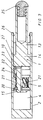
- the braking and damping element comprises a piston 1 which is displaceably arranged in a cylinder 2 provided with a blind hole, the length of the displacement path of the piston 1 being adapted to the path of the automatic closing of the drawer guide.
- the piston 1 and the piston collar 14, runs with loose fit in the cylinder 2 and is actuated by means of a piston rod 13.
- a pin 15 is disposed opposite the piston rod 13 on the piston collar 14.
- Between the piston collar 14 and the inner wall of the cylinder 1 remains an air-permeable gap 27.
- annular seal 3 is arranged at the front end of the pin 15, which seals the piston 1 against the inner wall of the cylinder 1.
- a pressure in the compression chamber 4 of the cylinder 1 which increases sharply with increasing piston travel.
- a slide valve 8 is arranged, which can move freely axially along the pin 15 between the seal 3 and the piston collar 14.
- the slide valve 8 has a sliding seal 7, which bears against the inner wall of the cylinder.
- the friction between the sliding seal 7 and the inner wall of the cylinder 1 is set so that it is considerably larger than the friction between the base body of the slide valve 8 and the pin 15th
- the pin 15 has a vent hole 5, one end of which opens into the compression space and the other end into a valve cavity 11 between pin 15 and slide valve 8.
- vent hole 5 is closed by the valve sealing lip 6 of the slide valve 8 and it can escape air from the compression chamber 4 through the vent hole 5.
- the counterforce can be applied to the with the mounting hole 12 by means of a coupling device, for. As retraction device, or by a buffer 13 ( Figure 3) docked drawer 14 are transmitted, whereby it is slowed down.
- the drawer comes to a complete standstill or almost to a standstill. Consequently, the sliding friction of the friction surface 9 of the sliding seal 7 is reduced or canceled on the cylinder wall, or by the recoil caused by the compressed air in the compression chamber 4, the piston 1 is printed back in the direction of arrow 17 a minimum (a few 1/100th of a millimeter). On the other hand, the sliding valve 8 remains in its position, as it is held by the friction between the friction surface 9 and the cylinder wall.
- a certain leakage rate can be selected, which allows the clean slow closing the drawer after the steaming without damping resistance.
- a complete overriding of the damper can be achieved by an overflow channel 28, whereby a full closing of the drawer can be done.
- this damper can also be used separately for drawers or door fronts of hinged doors.
- Figure 2 shows the use of a vent channel 19 on the surface of the pin 15 instead of a vent hole, as shown in Figures 1 and 3-6.
- a return spring 18 is provided which pushes back the piston 1 of the brake and damping element when needed in its initial position.
- Figure 3 shows a seal 20 and a slide valve 22, which are integrally connected to each other by means of an elastic intermediate piece 21.
- the sliding valve has, in addition to the sealing lip 23, an additional sliding seal 24 for sealing the valve cavity 11 with respect to the pin 15.
- the "characteristic" of the slide valve 22 can be adjusted.
Landscapes
- Engineering & Computer Science (AREA)
- General Engineering & Computer Science (AREA)
- Mechanical Engineering (AREA)
- Closing And Opening Devices For Wings, And Checks For Wings (AREA)
- Drawers Of Furniture (AREA)
- Fluid-Damping Devices (AREA)
Description
- Die Erfindung betrifft ein Brems- und Dämpfungselement für bewegliche Möbelteile nach dem Oberbegriff des Patentanspruchs 1.
- Brems- und Dämpfungselemente sind in vielfältigen Ausführungsformen in der Technik bekannt und werden in den unterschiedlichsten Anwendungsgebieten eingesetzt.
- So sind unter anderem hydraulische Stoßdämpfer bekannt, die eine Kolben-Zylinder-Anordnung aufweisen mit zwei Arbeitskammern, zwischen welchen ein flüssiges Medium strömt, das den Bremseffekt bewirkt. Derartige Dämpfer haben eine hohe Haftreibung, bedingt durch Kolbenstangen- und Kolbenabdichtungen, die einer sinnvollen Reduktion der Baugröße Grenzen setzt. Ferner sind sie sehr aufwendig und teuer in der Herstellung und werden daher nur für spezielle Anwendungen eingesetzt, bei denen Kosten eine untergeordnete Rolle spielen.
- Für den Einsatz als Brems- und Dämpfungselement für bewegliche Möbelteile, insbesondere Schubladen, sind hydraulische Stoßdämpfer nicht oder nur bedingt geeignet.
- Die Dichtung von Ölhydraulikdämpfern muss um einen Verlust des Öles zu vermeiden fast hermetisch dicht sein. Um dies zu erreichen, sind hochwertige Kolbenstangenoberflächen sowie stark anpressende Dichtlippen erforderlich, die zum einen sehr aufwendig und teuer sind und zum anderen hohe Reibung aufweisen, die teilweise die Einzugsvorrichtung der Schublade aufhebt. Zudem entsteht durch die Verdrängung des Volumens der Kolbenstange ein Überdruck im geschlossenen Zustand, der einer Einzugsvorrichtung ebenfalls entgegensteht. Diese Systeme haben kaum mehr Selbsteinzug oder verursachen große Öffnungskräfte für die Schubladen. Öldämpfer können besonders bei reibungsarmen Kolbenstangenabdichtungen auslaufen und verfrüht die Funktion aufgeben.
- Alle Öldämpfer haben grundsätzlich nur eine Dämpfkurve die nur für einen engen Geschwindigkeits- und Massebereich angewendet werden kann. Schwere Schubladen oder Auszüge die mit hohen Geschwindigkeiten geschlossen werden können nicht mehr gedämpft werden, bzw. leichte langsame Schubladen bleiben stecken.
- Bei Möbeln, insbesondere Schubladen und Möbeltüren, werden ebenfalls auf Reibung basierende Brems- und Dämpfungselemente meist in Verbindung mit Federelementen eingesetzt. Derartige Bremselemente sind in der DE 199 15 164 A1 oder der DE 197 17 937 A1 offenbart.
- Es sind derzeit noch Pufferungen am Markt. Puffer bauen kaum Energie ab, sie dienen zwar etwas zur Geräuschmilderung, sind aber nicht geeignet, Energie in der benötigten Menge abzubauen.
- Die DE 37 29 597 A offenbart ein Brems- und Dämpfungselement als Türschließeinrichtung, mit einem in einem zylindrischen Raum über eine Dichtung abdichtend geführten Kolben, wobei bei Bewegung des Kolbens in den Zylinder hinein ein Luftdruckaufbau in einem von Zylinder und Kolben umschlossenen Kompressionsraumes erfolgt. Weiterhin ist eine Ventileinrichtung vorgesehen, die eine Entlüftung des Kompressionsraumes ab einer vordefinierten Eintauchlänge des Kolbens in den Zylinder bewirkt. Die Ventileinrichtung besteht aus einem am Boden des Zylinders im Kompressionsraum befestigten Zapfen, der eine Durchgangsbohrung im Zentrum des Kolbens durchgreift und dort gleitend aufgenommen ist. Der Zapfen ist leicht konisch ausgebildet und wird im Durchmesser vom Boden des Zylinders in Richtung Durchgangsbohrung größer und dichtet diese zu Beginn des Einfahrens des Kolbens in den Zylinder über eine vordefinierte Teilstrecke ab. Taucht der Kolben tiefer in den Zylinder ein und damit der konusförmige Zapfen in die Durchgangsbohrung im Kolben, so entsteht dort ein immer größer werdender Ringspalt zwischen Durchgangsbohrung und Zapfen, Durch diesen Ringspalt entweicht die im Kompressionsraum befindliche unter Druck stehende Luft aus dem Zylinder ins Freie bis zum Druckausgleich. Um ein Durchschlagen des Kolbens zu vermeiden und den Kolben automatisch wieder in Ausgangsstellung aus dem Zylinder fahren zu können, arbeitet der Kolben gegen die Kraft einer Rückstellfeder, die den Zapfen als Schraubenfeder umgibt.
- Die US 5,799,759 offenbart ein Brems- und Dämpfungselement allgemein für bewegliche Teile, mit einem in einem zylindrischen Raum abdichtend geführten Kolben, wobei bei Bewegung des Kolbens in den Zylinder hinein ein Druckaufbau in einem von Zylinder und Kolben umschlossenen Kompressionsraum erfolgt, wobei eine Kombination einer Dichtung mit-einer am und/oder im Kolben angeordneten Ventileinrichtung vorgesehen ist, und die Dichtung auf einem dem Kompressionsraum zugewandten Zapfen des Kolbens angeordnet ist, und die Ventileinrichtung teilweise an der Innenwand des Zylinders anliegt und eine Entlüftungsbohrung oder einen Entlüftungskanal umfasst, deren / dessen eines Ende in den Kompressionsraum und deren /dessen anderes Ende in einen Ventilhohlraum mündet, der von einer Dichtlippe eines Schiebeventils der Ventileinrichtung verschlossen bzw. geöffnet wird, so dass durch Reibungskräfte gesteuert eine Entlüftung des Kompressionsraumes bei Stillstand des Kolbens oder einer Bewegung des Kolbens entgegen der Schließrichtung erfolgt.
- Die Aufgabe der Erfindung ist es, ein preiswert herzustellendes Brems- und Dämpfungselement für bewegliche Möbelteile vorzuschlagen, das in der Lage ist, eine Schublade oder Türfront eines Möbels so abzudämpfen, dass beim Schließvorgang keine Erschütterungen oder Schlaggeräusche auftreten. Der Funktionsbereich soll sich von der leeren langsam geschlossenen Schublade bis zu einem voll beladenen schnell geschlossenen Auszug erstrecken.
- Die Lösung dieser Aufgabe erfolgt erfindungsgemäß durch die Merkmale des Patentanspruchs 1.
- Wesentliches Merkmal des erfindungsgemäßen Brems- und Dämpfungselements ist, dass die Dichtung am vorderen freien Ende des Zapfens angeordnet ist und das Schiebeventil der Ventileinrichtung auf dem Zapfen des Kolbens zwischen der Dichtung und einem Kolbenbund des Kolbens angeordnet ist.
- Grundlage dabei ist eine am und/oder im Kolben angeordnete Ventileinrichtung, die teilweise an der Zylinderwand anliegt und durch Reibungskräfte gesteuert eine Entlüftung des Kompressionsraumes bei Stillstand des Kolbens oder einer Bewegung des Kolbens entgegen der Schließrichtung bewirkt.
- Hierdurch ergibt sich trotz einfachem und kostengünstigem Aufbau ein funktionssicheres und verschleißarmes Brems- und Dämpfungselement. Die vor der Ventilanordnung angeordnete Dichtung gewährleistet einen drucklosen Raum, in dem sich die Ventileinrichtung befindet. Dadurch wirken nur geringe Kräfte auf die Ventilanordnung.
- Vorteilhafte Ausführungsformen und Weiterbildungen der Erfindung ergeben sich aus den abhängigen Patentansprüchen.
- Die Abdichtung zwischen Kolben und Zylinder erfolgt durch eine Ringdichtung, die am freien Ende eines dem Kompressionsraum zugewandten Zapfens am Kolben angeordnet ist.
- In einer bevorzugten Ausführungsform ist das vorzugsweise etwa ring- oder zylinderförmige, Schiebeventil am Zapfen des Kolbens verschiebbar angeordnet. Je nachdem ob sich der Kolben in den Zylinder hinein bewegt, stillsteht oder aus dem Zylinder herausbewegt verändert sich die Position des Schiebeventils auf dem Zapfen.
- Dies wird vorzugsweise erreicht durch eine Gleitdichtung, die an der Innenwand des Zylinders anliegt und die Reibungskräfte zwischen Schiebeventil und Zylinderinnenwand hervorruft, die das Schiebeventil steuern.
- Die Reibung zwischen Gleitdichtung und Innenwand des Zylinders muss größer sein, als die Reibung zwischen Grundkörper des Schiebeventils und dem Zapfen.
- Die Dichtlippe des Schiebeventils wirkt mit einer zugeordneten Dichtfläche am Kolben zusammen.
- Die Dichtlippe verschließt bzw. öffnet den Ventilhohlraum, wobei die Ventileinrichtung eine Entlüftungsbohrung umfasst, deren eines Ende in den Kompressionsraum und deren anderes Ende in den Ventilhohlraum mündet. Anstelle der Entlüftungsbohrung kann auch ein Entlüftungskanal verwendet werden, der außen am Zapfen angebracht ist.
- In einer vorteilhaften Ausführungsform ist vorgesehen, die Dichtung und das Schiebeventil einstückig auszubilden, wobei die Teile durch ein elastisches Zwischenstück miteinander verbunden sind.
- Ferner kann zwischen Kolben und Zylinder eine Rückstellfeder eingesetzt sein, so dass das Brems- und Dämpfungselement z.B. in Verbindung mit Scharnieren eingesetzt werden kann.
- Die Innenwand des Zylinders kann vorzugsweise einen Überströmkanal aufweisen, der bei einer bestimmten Stellung des Kolbens die Wirkung der Dichtung außer Kraft setzt. Dies ist bei Schubladen vorteilhaft, die über eine sogenannte automatische Einzugsvorrichtung verfügen.
- Bevorzugte Ausführungsbeispiele der Erfindung werden nachfolgend anhand von mehreren Zeichnungsfiguren beschrieben. Aus den Zeichnungen und ihrer Beschreibung ergeben sich weitere Merkmale, Vorteile und Anwendungsmöglichkeiten der Erfindung.
- Es zeigt:
- Figur 1:
- Einen Schnitt durch eine erste Ausführungsform des Brems- und Dämpfungselements;
- Figur 2:
- Einen Schnitt durch eine zweite Ausführungsform des Brems- und Dämpfungselements;
- Figur 3:
- Einen Schnitt durch eine dritte Ausführungsform des Brems- und Dämpfungselements;
- Figur 4:
- Vergrößerte Darstellung der Ventilanordnung gemäss Figur 1 bei geschlossenem Schiebeventil;
- Figur 5:
- Vergrößerte Darstellung der Ventilanordnung gemäss Figur 1 bei leicht geöffnetem Schiebeventil;
- Figur 6:
- Vergrößerte Darstellung der Ventilanordnung gemäss Figur 1 bei vollständig geöffnetem Schiebeventil.
- Die folgenden Beispiele beschreiben den Einsatz des Brems- und Dämpfungselements bei einer Schublade.
- Gemäss Figur 1 umfasst das Brems- und Dämpfungselement einen Kolben 1, der in einem mit einem Sackloch versehenen Zylinder 2 verschiebbar angeordnet ist, wobei die Länge des Verschiebewegs des Kolbens 1 dem Weg der Schließautomatik der Schubladenführung angepasst ist. Der Kolben 1 bzw. der Kolbenbund 14, läuft mit loser Passung in dem Zylinder 2 und wird mittels einer Kolbenstange 13 betätigt. Ein Zapfen 15 ist gegenüberliegend der Kolbenstange 13 am Kolbenbund 14 angeordnet. Zwischen dem Kolbenbund 14 und der Innenwand des Zylinders 1 verbleibt ein luftdurchlässiger Spalt 27. Dieser grundlegende Aufbau findet sich auch in den Ausführungsbeispielen gemäss den Figuren 2 und 3 wieder.
- Wie man in Figur 1 erkennt, ist am vorderen Ende des Zapfens 15 eine ringförmige Dichtung 3 angeordnet, die den Kolben 1 gegen die Innenwand des Zylinders 1 abdichtet. Bei Bewegung des Kolbens 1 in Pfeilrichtung 16 entsteht durch die Abdichtung ein Druck im Kompressionsraum 4 des Zylinders 1, der mit zunehmendem Kolbenweg stark zunimmt.
- Auf dem Zapfen 15 ist ein Schiebeventil 8 angeordnet, welches sich frei axial entlang des Zapfens 15 zwischen der Dichtung 3 und dem Kolbenbund 14 bewegen kann. Dazu ist der am Außenumfang anliegende Grundköper des Schiebeventils derart ausgebildet, dass er gut auf dem Zapfen gleitet. Das Schiebeventil 8 weist eine Gleitdichtung 7 auf, die an der Innenwand des Zylinders anliegt. Die Reibung zwischen der Gleitdichtung 7 und der Innenwand des Zylinders 1 ist derart eingestellt, dass die erheblich größer ist als die Reibung zwischen Grundkörper des Schiebeventils 8 und dem Zapfen 15.
- Der Zapfen 15 weist eine Entlüftungsbohrung 5 auf, deren eines Ende in den Kompressionsraum und deren anderes Ende in einen Ventilhohlraum 11 zwischen Zapfen 15 und Schiebeventil 8 mündet.
- Bei Bewegung des Kolbens 1 in Pfeilrichtung 16 wird aufgrund der Reibung der Reibfläche 9 der Gleitdichtung 7 an der Innenwand des Zylinders 2 das Schiebeventil 8 bzw. dessen Dichtlippe 6 an die Dichtfläche 10 des Kolbenbunds 14 angedrückt. Dieser Zustand ist im einzelnen in Figur 4 dargestellt.
- Somit wird die in den Ventilhohlraum 11 mündende Entlüftungsbohrung 5 durch die Ventildichtlippe 6 des Schiebeventils 8 verschlossen und es kann keine Luft aus dem Kompressionsraum 4 durch die Entlüftungsbohrung 5 entweichen.
- Der im Schiebeventilraum 11 auftretende Druck verursacht durch die rundum fast oder ganz gleichen Querschnitte keine Verschiebekraft auf das Schiebeventil 8 wodurch dieses fast oder ganz ausschließüch durch die vorhin beschriebene Reibung gesteuert wird.
- Wird der Kolben 1 weiter in Pfeilrichtung 16 bewegt, so erfolgt ein zunehmender Druckaufbau im Kompressionsraum 4, der eine Gegenkraft auf den Kolben 1 erzeugt. Die Gegenkraft kann auf die mit dem Befestigungsloch 12 mittels einer Koppeleinrichtung, z. B. Einzugsvorrichtung, oder durch einen Puffer 13 (Figur 3) angedockten Schublade 14 übertragen werden, wodurch diese abgebremst wird.
- Dadurch gerät die Schublade ganz zum Stillstand oder fast zum Stillstand. Folglich wird die Gleitreibung der Reibfläche 9 der Gleitdichtung 7 an der Zylinderwand reduziert oder aufgehoben, bzw. durch den von der komprimierten Luft im Kompressionsraum 4 verursachten Rückstoß wird der Kolben 1 minimal (wenige 1/100stel Millimeter) in Pfeilrichtung 17 zurückgedruckt. Hingegen verbleibt das Schiebeventil 8 in seiner Position, da es durch die Reibung zwischen Reibfläche 9 und Zylinderwand festgehalten wird.
- Dadurch löst sich die Dichtlippe 6 - wie es in Figur 5 dargestellt ist - etwas von der Dichtfläche 10 am Kolbenbund 14, es entsteht ein Spalt 29 und die komprimierte Luft kann aus dem Kompressionsraum 4 durch die Entlüftungsbohrung 5 vorbei an der Ventildichtlippe 6 durch den Spalt 29 und den Spalt 27 des Kolbenraumes ins Freie entweichen. Der Druck im Kompressionsraum 4 baut sich schlagartig ab.
- Durch den sehr raschen Druckabbau im Kompressionsraum 4 wird der Rückstoß und die Kolbengegenkraft schlagartig gestoppt, wodurch der Kolben 1 und somit die Schublade stehen bleibt. Die in diesem Funktionsbereich üblicherweise angebrachten Einzugsvorrichtungen (durch Feder oder Schwerkraft) bringen die Schublade langsam in Endstellung.
- Durch die Ausformung der Dichtfläche 10 und/oder der Ventildichtlippe 6 des Schiebeventils 8 sowie durch ein optional angebrachtes elastisches Zwischenstück 21 (Figur 3) kann eine gewisse Leckluftrate gewählt werden, die das saubere langsame Schließen der Schublade nach dem Dämpfvorgang ohne Dämpfwiderstand ermöglicht. In den letzten Millimetern des Schließweges kann durch einen Überströmkanal 28 eine völlige Außerkraftsetzung des Dämpfers erreicht werden, wodurch ein sattes Schließen der Schublade erfolgen kann.
- In Figur 6 ist dargestellt, dass beim Öffnen der Schublade die Kolbenstange 1 durch die Schubladenkoppelvorrichtung (wie sie in der Einzugsautomatik der Schubladenführung vorhanden sein mag) oder mittels Rückstellfeder 18 in Pfeilrichtung 17 bewegt und wieder in Betriebsbereitschaft gebracht wird, wobei in diesem Betriebsfall das Schiebeventil 8 durch Reibung der Reibfläche 9 ständig im geöffneten Zustand gehalten wird, d.h. die Dichtlippe 6 des Schiebeventils 8 gibt die Entlüftungsbohrung 5 vollständig frei, der Spalt 29 erreicht seine maximale Größe. Dadurch ist völliger Druckausgleich beim öffnen der Schublade und somit keinerlei Behinderung durch erhöhte Öffnungskräfte vorhanden.
- Durch Einsetzen einer Rückstellfeder 18 kann dieser Dämpfer auch separat für Schubladen oder Türfronten von mittels Scharnieren befestigten Türen verwendet werden.
- Figur 2 zeigt den Einsatz eines Entlüftungskanals 19 an der Oberfläche des Zapfens 15 anstelle einer Entlüftungsbohrung, wie sie in den Figuren 1 und 3-6 dargestellt ist.
- Ferner ist bei Figur 2 eine Rückstellfeder 18 vorgesehen, die den Kolben 1 des Brems- und Dämpfungselements bei Bedarf in seine Ausgangsstellung zurückdrückt.
- Figur 3 zeigt eine Dichtung 20 und ein Schiebeventil 22, die mittels eines elastischen Zwischenstücks 21 einstückig miteinander verbunden sind. Das Schiebeventil weist neben der Dichtlippe 23 eine zusätzliche Gleitdichtung 24 zur Abdichtung des Ventilhohlraums 11 gegenüber dem Zapfen 15 auf. Mittels des elastischen Zwischenstücks kann die "Charakteristik" des Schiebeventils 22 eingestellt werden.
-
- 1
- Kolben
- 2
- Zylinder
- 3
- Dichtung
- 4
- Kompressionsraum
- 5
- Entlüftungsbohrung
- 6
- Dichtlippe
- 7
- Gleitdichtung
- 8
- Schiebeventil
- 9
- Reibfläche
- 10
- Dichtfläche
- 11
- Ventilhohlraum
- 12
- Befestigungsloch
- 13
- Kolbenstange
- 14
- Kolbenbund
- 15
- Kolbenzapfen
- 16
- Pfeilrichtung
- 17
- Pfeilrichtung
- 18
- Rückstellfeder
- 19
- Entlüftungskanal
- 20
- Dichtung
- 21
- elastisches Zwischenstück
- 22
- Schiebeventil
- 23
- Dichtlippe
- 24
- Gleitdichtung
- 25
- Puffer
- 26
- Kralle
- 27
- Spalt
- 28
- Überströmkanal
- 29
- Spalt
Claims (8)
- Brems- und Dämpfungselement für bewegliche Möbelteile mit einem in einem zylindrischen Raum abdichtend geführten Kolben (1), wobei bei Bewegung des Kolbens (1) in den Zylinder (2) hinein ein Druckaufbau in einem von Zylinder (2) und Kolben (1) umschlossenen Kompressionsraum (4) erfolgt, wobei eine Kombination einer Dichtung (3; 20) mit einer am und/oder im Kolben (1) angeordneten Ventileinrichtung vorgesehen ist, und die Dichtung (3; 20) auf einem dem Kompressionsraum (4) zugewandten Zapfen (15) des Kolbens (1) angeordnet ist, und die Ventileinrichtung teilweise an der Innenwand des Zylinders (2) anliegt und eine Entlüftungsbohrung (5) oder einen Entlüftungskanal (19) umfasst, deren /dessen eines Ende in den Kompressionsraum (4) und deren / dessen anderes Ende in einen Ventilhohlraum (11) mündet, der von einer Dichtlippe (6) eines Schiebeventils (8) der Ventileinrichtung verschlossen bzw. geöffnet wird, so dass durch Reibungskräfte gesteuert eine Entlüftung des Kompressionsraumes (4) bei Stillstand des Kolbens (1) oder einer Bewegung des Kolbens (1) entgegen der Schließrichtung (16) erfolgt, dadurch gekennzeichnet, dass die Dichtung (3; 20) am vorderen freien Ende des Zapfens (15) angeordnet ist und das Schiebeventil (8) der Ventileinrichtung auf dem Zapfen (15) des Kolbens (1) zwischen der Dichtung (3; 20) und einem Kolbenbund (14) des Kolbens (1) angeordnet ist.
- Brems- und Dämpfungselement nach Anspruch 1, dadurch gekennzeichnet, dass das Schiebeventil (8) auf dem Zapfen (15) des Kolbens verschiebbar angeordnet ist.
- Brems- und Dämpfungselement nach einem der Ansprüche 1 oder 2, dadurch gekennzeichnet, dass das Schiebeventil (8) eine Gleitdichtung (7) aufweist, die an der Innenwand des Zylinders (1) anliegt.
- Brems- und Dämpfungselement nach Anspruch 3, dadurch gekennzeichnet, dass die Reibung zwischen Gleitdichtung (7) und Innenwand des Zylinders (2) größer ist als die Reibung zwischen Grundkörper des Schiebeventils (8) und dem Zapfen (15).
- Brems- und Dämpfungselement nach einem der Ansprüche 1 bis 4, dadurch gekennzeichnet, dass die Dichtlippe (6) des Schiebeventils mit einer zugeordneten Dichtfläche (10) am Kolben (1) zusammenwirkt.
- Brems- und Dämpfungselement nach einem der Ansprüche 1 bis 5, dadurch gekennzeichnet, dass die Dichtung (20) des Kolbens (1) und das Schiebeventil (22) einstückig ausgebildet und durch ein elastisches Zwischenstück (21) miteinander verbunden sind.
- Brems- und Dämpfungselement nach einem der Ansprüche 1 bis 6, dadurch gekennzeichnet, dass zwischen Kolben (1) und Zylinder (2) eine Rückstellfeder (18) eingesetzt ist.
- Brems- und Dämpfungselement nach einem der Ansprüche 1 bis 7, dadurch gekennzeichnet, dass die Innenwand des Zylinders (2) einen Überströmkanal (28) aufweist, der bei einer bestimmten Stellung des Kolbens (1) die Wirkung der Dichtung (3; 20) außer Kraft setzt.
Applications Claiming Priority (2)
| Application Number | Priority Date | Filing Date | Title |
|---|---|---|---|
| DE10054904 | 2000-11-06 | ||
| DE10054904A DE10054904A1 (de) | 2000-11-06 | 2000-11-06 | Brems- und Dämpfungselement für bewegliche Möbelteile |
Publications (3)
| Publication Number | Publication Date |
|---|---|
| EP1211375A2 EP1211375A2 (de) | 2002-06-05 |
| EP1211375A3 EP1211375A3 (de) | 2003-06-18 |
| EP1211375B1 true EP1211375B1 (de) | 2006-02-01 |
Family
ID=7662270
Family Applications (1)
| Application Number | Title | Priority Date | Filing Date |
|---|---|---|---|
| EP01126086A Expired - Lifetime EP1211375B1 (de) | 2000-11-06 | 2001-11-02 | Brems- und Dämpfungselement für bewegliche Möbelteile |
Country Status (3)
| Country | Link |
|---|---|
| EP (1) | EP1211375B1 (de) |
| AT (2) | AT5527U1 (de) |
| DE (2) | DE10054904A1 (de) |
Families Citing this family (10)
| Publication number | Priority date | Publication date | Assignee | Title |
|---|---|---|---|---|
| DE10251169A1 (de) * | 2002-10-31 | 2004-05-19 | Karl Simon Gmbh & Co. Kg | Anschlagdämpfer |
| DE20311217U1 (de) * | 2003-07-22 | 2003-10-23 | Vauth-Sagel GmbH & Co. Grundstücksverwaltung, 33034 Brakel | Luftdämpfer |
| AT413630B (de) * | 2003-07-24 | 2006-04-15 | Fulterer Gmbh | Ausziehsperreinrichtung |
| AT413473B (de) * | 2003-11-21 | 2006-03-15 | Fulterer Gmbh | Selbsteinzugvorrichtung |
| DE102005052125A1 (de) * | 2005-10-28 | 2007-05-16 | Simon Karl Gmbh & Co Kg | Anschlagdämpfer |
| DE202006003197U1 (de) * | 2006-03-01 | 2007-07-12 | Hettich-Oni Gmbh & Co. Kg | Dämpfer für Möbel |
| DE202006006188U1 (de) * | 2006-04-18 | 2007-08-30 | Paul Hettich Gmbh & Co. Kg | Möbel |
| CN100572846C (zh) * | 2006-04-28 | 2009-12-23 | 王明根 | 缓冲汽缸装置 |
| DE102006040085A1 (de) * | 2006-08-28 | 2008-03-20 | Zimmer, Günther | Kostengünstig herstellbare pneumatische Verzögerungsvorrichtung |
| DE102009041656A1 (de) * | 2009-09-17 | 2011-03-24 | Grass Gmbh | Möbel und Vorrichtung zur Verriegelung eines Möbelteils |
Family Cites Families (10)
| Publication number | Priority date | Publication date | Assignee | Title |
|---|---|---|---|---|
| US1247274A (en) * | 1917-03-14 | 1917-11-20 | Louis Auer | Door check and closer. |
| DE1809854U (de) * | 1960-02-23 | 1960-04-14 | Paul Gaerthe K G | Tuerpuffer. |
| FR1370477A (fr) * | 1963-07-11 | 1964-08-21 | Perfectionnements aux amortisseurs pneumatiques, notamment pour ferme-porte | |
| FR2410190A1 (fr) * | 1977-11-23 | 1979-06-22 | Allinquant J G | Piston perfectionne pour ressort pneumatique ou analogue |
| DE3729597A1 (de) * | 1987-09-04 | 1989-03-16 | Karl Liedgens | Tuerschliessdaempfer |
| DE4212079C2 (de) * | 1992-04-10 | 2003-04-10 | Stabilus Gmbh | Fluidendruckfeder und Konstruktion mit einer solchen Fluidendruckfeder |
| DE19609040C2 (de) * | 1996-03-08 | 1999-05-27 | Stabilus Gmbh | Feststellelement |
| DE19717937A1 (de) * | 1996-11-08 | 1998-05-20 | Grass Ag | Brems- und Dämpfungselement für bewegliche Möbelteile |
| DE19755080B4 (de) * | 1997-12-11 | 2004-12-02 | Stabilus Gmbh | Gasfeder mit Zwischenstopfunktion und Temperaturkompensation |
| DE29805992U1 (de) | 1998-04-01 | 1998-06-04 | Karl Rieker KG, 73084 Salach | Federzylinder zur Verwendung zusammen mit einem Möbelbeschlag |
-
2000
- 2000-11-06 DE DE10054904A patent/DE10054904A1/de not_active Withdrawn
-
2001
- 2001-10-29 AT AT0083501U patent/AT5527U1/de not_active IP Right Cessation
- 2001-11-02 DE DE50108840T patent/DE50108840D1/de not_active Expired - Lifetime
- 2001-11-02 EP EP01126086A patent/EP1211375B1/de not_active Expired - Lifetime
- 2001-11-02 AT AT01126086T patent/ATE317075T1/de active
Also Published As
| Publication number | Publication date |
|---|---|
| AT5527U1 (de) | 2002-08-26 |
| ATE317075T1 (de) | 2006-02-15 |
| DE50108840D1 (de) | 2006-04-13 |
| DE10054904A1 (de) | 2002-05-16 |
| EP1211375A3 (de) | 2003-06-18 |
| EP1211375A2 (de) | 2002-06-05 |
Similar Documents
| Publication | Publication Date | Title |
|---|---|---|
| EP1319787B1 (de) | Luftdämpfer für bewegliche Möbelteile | |
| DE2516478C3 (de) | Gasfeder | |
| DE602004008319T2 (de) | Fluiddämpfer | |
| EP1348828A2 (de) | Dämpfungsvorrichtung für bewegliche Möbelteile | |
| EP0386433B1 (de) | Hydraulischer Stossdämpfer | |
| EP1215414B1 (de) | Kolben-Zylinderaggregat mit einer geschwindigkeitsabhängigen Dämpfkraft | |
| EP0253072A2 (de) | Gasfeder mit Endlagendämpfung | |
| DE10028586C2 (de) | Stoßdämpfer | |
| DE19717937A1 (de) | Brems- und Dämpfungselement für bewegliche Möbelteile | |
| DE102005002007B4 (de) | Gasfeder | |
| DE202013008364U1 (de) | Dämpfer für bewegbare Möbelteile | |
| EP1828523A2 (de) | Anschlagdämpfer | |
| DE10121977B4 (de) | Möbelbeschlag mit Brems- und Dämpfungsvorrichtung | |
| EP1211375A2 (de) | Brems- und Dämpfungselement für bewegliche Möbelteile | |
| EP2807395A1 (de) | Vorrichtung zur dämpfung der bewegung eines beweglich gelagerten bauteils | |
| DE202009006233U1 (de) | Dämpferzylinder für eine Dämpfungseinrichtung für Möbel | |
| DE60009647T2 (de) | Hydraulikzylinder | |
| DE3546236A1 (de) | Gasfeder mit endlagendaempfung | |
| DE10145200B4 (de) | Türschließer | |
| DE68901665T2 (de) | Tuerschliesser. | |
| DE102005009762A1 (de) | Schwingungsdämpfer mit hydraulischem Endanschlag | |
| DE102016207324A1 (de) | Zuganschlag für eine Kolbenstange | |
| DE20302120U1 (de) | Flüssigkeitsdämpfer | |
| DE102006054257A1 (de) | Schwingungsdämpfer mit amplitudenabhängiger Dämpfkraft | |
| DE102012101618B4 (de) | Kolben-Zylinder-Einheit |
Legal Events
| Date | Code | Title | Description |
|---|---|---|---|
| PUAI | Public reference made under article 153(3) epc to a published international application that has entered the european phase |
Free format text: ORIGINAL CODE: 0009012 |
|
| AK | Designated contracting states |
Kind code of ref document: A2 Designated state(s): AT BE CH CY DE DK ES FI FR GB GR IE IT LI LU MC NL PT SE TR |
|
| AX | Request for extension of the european patent |
Free format text: AL;LT;LV;MK;RO;SI |
|
| PUAL | Search report despatched |
Free format text: ORIGINAL CODE: 0009013 |
|
| AK | Designated contracting states |
Designated state(s): AT BE CH CY DE DK ES FI FR GB GR IE IT LI LU MC NL PT SE TR |
|
| AX | Request for extension of the european patent |
Extension state: AL LT LV MK RO SI |
|
| RIC1 | Information provided on ipc code assigned before grant |
Ipc: 7E 05F 5/02 B Ipc: 7F 16F 9/516 A |
|
| 17P | Request for examination filed |
Effective date: 20031022 |
|
| AKX | Designation fees paid |
Designated state(s): AT BE CH CY DE DK ES FI FR GB GR IE IT LI LU MC NL PT SE TR |
|
| 17Q | First examination report despatched |
Effective date: 20050105 |
|
| GRAP | Despatch of communication of intention to grant a patent |
Free format text: ORIGINAL CODE: EPIDOSNIGR1 |
|
| GRAS | Grant fee paid |
Free format text: ORIGINAL CODE: EPIDOSNIGR3 |
|
| GRAA | (expected) grant |
Free format text: ORIGINAL CODE: 0009210 |
|
| AK | Designated contracting states |
Kind code of ref document: B1 Designated state(s): AT BE CH CY DE DK ES FI FR GB GR IE IT LI LU MC NL PT SE TR |
|
| PG25 | Lapsed in a contracting state [announced via postgrant information from national office to epo] |
Ref country code: IE Free format text: LAPSE BECAUSE OF FAILURE TO SUBMIT A TRANSLATION OF THE DESCRIPTION OR TO PAY THE FEE WITHIN THE PRESCRIBED TIME-LIMIT Effective date: 20060201 Ref country code: IT Free format text: LAPSE BECAUSE OF FAILURE TO SUBMIT A TRANSLATION OF THE DESCRIPTION OR TO PAY THE FEE WITHIN THE PRESCRIBED TIME-LIMIT;WARNING: LAPSES OF ITALIAN PATENTS WITH EFFECTIVE DATE BEFORE 2007 MAY HAVE OCCURRED AT ANY TIME BEFORE 2007. THE CORRECT EFFECTIVE DATE MAY BE DIFFERENT FROM THE ONE RECORDED. Effective date: 20060201 Ref country code: NL Free format text: LAPSE BECAUSE OF FAILURE TO SUBMIT A TRANSLATION OF THE DESCRIPTION OR TO PAY THE FEE WITHIN THE PRESCRIBED TIME-LIMIT Effective date: 20060201 Ref country code: FI Free format text: LAPSE BECAUSE OF FAILURE TO SUBMIT A TRANSLATION OF THE DESCRIPTION OR TO PAY THE FEE WITHIN THE PRESCRIBED TIME-LIMIT Effective date: 20060201 Ref country code: GB Free format text: LAPSE BECAUSE OF FAILURE TO SUBMIT A TRANSLATION OF THE DESCRIPTION OR TO PAY THE FEE WITHIN THE PRESCRIBED TIME-LIMIT Effective date: 20060201 |
|
| REG | Reference to a national code |
Ref country code: GB Ref legal event code: FG4D Free format text: NOT ENGLISH |
|
| REG | Reference to a national code |
Ref country code: CH Ref legal event code: EP |
|
| REG | Reference to a national code |
Ref country code: IE Ref legal event code: FG4D Free format text: LANGUAGE OF EP DOCUMENT: GERMAN |
|
| REF | Corresponds to: |
Ref document number: 50108840 Country of ref document: DE Date of ref document: 20060413 Kind code of ref document: P |
|
| PG25 | Lapsed in a contracting state [announced via postgrant information from national office to epo] |
Ref country code: DK Free format text: LAPSE BECAUSE OF FAILURE TO SUBMIT A TRANSLATION OF THE DESCRIPTION OR TO PAY THE FEE WITHIN THE PRESCRIBED TIME-LIMIT Effective date: 20060501 Ref country code: SE Free format text: LAPSE BECAUSE OF FAILURE TO SUBMIT A TRANSLATION OF THE DESCRIPTION OR TO PAY THE FEE WITHIN THE PRESCRIBED TIME-LIMIT Effective date: 20060501 |
|
| PG25 | Lapsed in a contracting state [announced via postgrant information from national office to epo] |
Ref country code: ES Free format text: LAPSE BECAUSE OF FAILURE TO SUBMIT A TRANSLATION OF THE DESCRIPTION OR TO PAY THE FEE WITHIN THE PRESCRIBED TIME-LIMIT Effective date: 20060512 |
|
| NLV1 | Nl: lapsed or annulled due to failure to fulfill the requirements of art. 29p and 29m of the patents act | ||
| PG25 | Lapsed in a contracting state [announced via postgrant information from national office to epo] |
Ref country code: PT Free format text: LAPSE BECAUSE OF FAILURE TO SUBMIT A TRANSLATION OF THE DESCRIPTION OR TO PAY THE FEE WITHIN THE PRESCRIBED TIME-LIMIT Effective date: 20060703 |
|
| GBV | Gb: ep patent (uk) treated as always having been void in accordance with gb section 77(7)/1977 [no translation filed] |
Effective date: 20060201 |
|
| REG | Reference to a national code |
Ref country code: IE Ref legal event code: FD4D |
|
| PG25 | Lapsed in a contracting state [announced via postgrant information from national office to epo] |
Ref country code: LI Free format text: LAPSE BECAUSE OF NON-PAYMENT OF DUE FEES Effective date: 20061130 Ref country code: MC Free format text: LAPSE BECAUSE OF NON-PAYMENT OF DUE FEES Effective date: 20061130 Ref country code: CH Free format text: LAPSE BECAUSE OF NON-PAYMENT OF DUE FEES Effective date: 20061130 Ref country code: BE Free format text: LAPSE BECAUSE OF NON-PAYMENT OF DUE FEES Effective date: 20061130 |
|
| PLBE | No opposition filed within time limit |
Free format text: ORIGINAL CODE: 0009261 |
|
| STAA | Information on the status of an ep patent application or granted ep patent |
Free format text: STATUS: NO OPPOSITION FILED WITHIN TIME LIMIT |
|
| 26N | No opposition filed |
Effective date: 20061103 |
|
| EN | Fr: translation not filed | ||
| REG | Reference to a national code |
Ref country code: CH Ref legal event code: PL |
|
| BERE | Be: lapsed |
Owner name: GRASS GMBH Effective date: 20061130 |
|
| PG25 | Lapsed in a contracting state [announced via postgrant information from national office to epo] |
Ref country code: FR Free format text: LAPSE BECAUSE OF FAILURE TO SUBMIT A TRANSLATION OF THE DESCRIPTION OR TO PAY THE FEE WITHIN THE PRESCRIBED TIME-LIMIT Effective date: 20070323 Ref country code: GR Free format text: LAPSE BECAUSE OF FAILURE TO SUBMIT A TRANSLATION OF THE DESCRIPTION OR TO PAY THE FEE WITHIN THE PRESCRIBED TIME-LIMIT Effective date: 20060502 |
|
| PG25 | Lapsed in a contracting state [announced via postgrant information from national office to epo] |
Ref country code: TR Free format text: LAPSE BECAUSE OF FAILURE TO SUBMIT A TRANSLATION OF THE DESCRIPTION OR TO PAY THE FEE WITHIN THE PRESCRIBED TIME-LIMIT Effective date: 20060201 Ref country code: LU Free format text: LAPSE BECAUSE OF NON-PAYMENT OF DUE FEES Effective date: 20061102 |
|
| PG25 | Lapsed in a contracting state [announced via postgrant information from national office to epo] |
Ref country code: FR Free format text: LAPSE BECAUSE OF FAILURE TO SUBMIT A TRANSLATION OF THE DESCRIPTION OR TO PAY THE FEE WITHIN THE PRESCRIBED TIME-LIMIT Effective date: 20060201 Ref country code: CY Free format text: LAPSE BECAUSE OF FAILURE TO SUBMIT A TRANSLATION OF THE DESCRIPTION OR TO PAY THE FEE WITHIN THE PRESCRIBED TIME-LIMIT Effective date: 20060201 |
|
| PGFP | Annual fee paid to national office [announced via postgrant information from national office to epo] |
Ref country code: IT Payment date: 20100927 Year of fee payment: 10 |
|
| PG25 | Lapsed in a contracting state [announced via postgrant information from national office to epo] |
Ref country code: IT Free format text: LAPSE BECAUSE OF NON-PAYMENT OF DUE FEES Effective date: 20121102 |
|
| PGFP | Annual fee paid to national office [announced via postgrant information from national office to epo] |
Ref country code: AT Payment date: 20171121 Year of fee payment: 17 |
|
| PGFP | Annual fee paid to national office [announced via postgrant information from national office to epo] |
Ref country code: DE Payment date: 20181120 Year of fee payment: 18 |
|
| REG | Reference to a national code |
Ref country code: AT Ref legal event code: MM01 Ref document number: 317075 Country of ref document: AT Kind code of ref document: T Effective date: 20181102 |
|
| PG25 | Lapsed in a contracting state [announced via postgrant information from national office to epo] |
Ref country code: AT Free format text: LAPSE BECAUSE OF NON-PAYMENT OF DUE FEES Effective date: 20181102 |
|
| REG | Reference to a national code |
Ref country code: DE Ref legal event code: R119 Ref document number: 50108840 Country of ref document: DE |
|
| PG25 | Lapsed in a contracting state [announced via postgrant information from national office to epo] |
Ref country code: DE Free format text: LAPSE BECAUSE OF NON-PAYMENT OF DUE FEES Effective date: 20200603 |