EP1211402A2 - Estimation de la quantité d'EGR interne pour la commande des soupapes et de l'allumage - Google Patents
Estimation de la quantité d'EGR interne pour la commande des soupapes et de l'allumage Download PDFInfo
- Publication number
- EP1211402A2 EP1211402A2 EP01116955A EP01116955A EP1211402A2 EP 1211402 A2 EP1211402 A2 EP 1211402A2 EP 01116955 A EP01116955 A EP 01116955A EP 01116955 A EP01116955 A EP 01116955A EP 1211402 A2 EP1211402 A2 EP 1211402A2
- Authority
- EP
- European Patent Office
- Prior art keywords
- intake
- internal egr
- engine
- accordance
- overlap
- Prior art date
- Legal status (The legal status is an assumption and is not a legal conclusion. Google has not performed a legal analysis and makes no representation as to the accuracy of the status listed.)
- Granted
Links
- 238000012937 correction Methods 0.000 claims abstract description 29
- 238000000034 method Methods 0.000 claims description 49
- 238000002485 combustion reaction Methods 0.000 claims description 24
- 230000004048 modification Effects 0.000 claims description 22
- 238000012986 modification Methods 0.000 claims description 22
- 230000035484 reaction time Effects 0.000 claims description 8
- 230000003247 decreasing effect Effects 0.000 claims description 5
- 239000007789 gas Substances 0.000 abstract description 36
- 239000000446 fuel Substances 0.000 description 14
- 230000007423 decrease Effects 0.000 description 11
- 230000008859 change Effects 0.000 description 4
- 238000010586 diagram Methods 0.000 description 4
- 238000002347 injection Methods 0.000 description 4
- 239000007924 injection Substances 0.000 description 4
- 238000012935 Averaging Methods 0.000 description 3
- 238000006243 chemical reaction Methods 0.000 description 3
- 238000013459 approach Methods 0.000 description 2
- 230000010354 integration Effects 0.000 description 2
- 230000008569 process Effects 0.000 description 2
- 230000008707 rearrangement Effects 0.000 description 2
- 230000004044 response Effects 0.000 description 2
- 238000000926 separation method Methods 0.000 description 2
- 230000001052 transient effect Effects 0.000 description 2
- 230000005540 biological transmission Effects 0.000 description 1
- 230000006835 compression Effects 0.000 description 1
- 238000007906 compression Methods 0.000 description 1
- 239000000203 mixture Substances 0.000 description 1
- 230000007935 neutral effect Effects 0.000 description 1
- 230000010349 pulsation Effects 0.000 description 1
- 230000003252 repetitive effect Effects 0.000 description 1
- 230000002000 scavenging effect Effects 0.000 description 1
- 238000006467 substitution reaction Methods 0.000 description 1
Images







Classifications
-
- F—MECHANICAL ENGINEERING; LIGHTING; HEATING; WEAPONS; BLASTING
- F02—COMBUSTION ENGINES; HOT-GAS OR COMBUSTION-PRODUCT ENGINE PLANTS
- F02D—CONTROLLING COMBUSTION ENGINES
- F02D13/00—Controlling the engine output power by varying inlet or exhaust valve operating characteristics, e.g. timing
- F02D13/02—Controlling the engine output power by varying inlet or exhaust valve operating characteristics, e.g. timing during engine operation
- F02D13/0261—Controlling the valve overlap
-
- F—MECHANICAL ENGINEERING; LIGHTING; HEATING; WEAPONS; BLASTING
- F02—COMBUSTION ENGINES; HOT-GAS OR COMBUSTION-PRODUCT ENGINE PLANTS
- F02D—CONTROLLING COMBUSTION ENGINES
- F02D13/00—Controlling the engine output power by varying inlet or exhaust valve operating characteristics, e.g. timing
- F02D13/02—Controlling the engine output power by varying inlet or exhaust valve operating characteristics, e.g. timing during engine operation
- F02D13/0203—Variable control of intake and exhaust valves
- F02D13/0215—Variable control of intake and exhaust valves changing the valve timing only
-
- F—MECHANICAL ENGINEERING; LIGHTING; HEATING; WEAPONS; BLASTING
- F02—COMBUSTION ENGINES; HOT-GAS OR COMBUSTION-PRODUCT ENGINE PLANTS
- F02D—CONTROLLING COMBUSTION ENGINES
- F02D21/00—Controlling engines characterised by their being supplied with non-airborne oxygen or other non-fuel gas
- F02D21/06—Controlling engines characterised by their being supplied with non-airborne oxygen or other non-fuel gas peculiar to engines having other non-fuel gas added to combustion air
- F02D21/08—Controlling engines characterised by their being supplied with non-airborne oxygen or other non-fuel gas peculiar to engines having other non-fuel gas added to combustion air the other gas being the exhaust gas of engine
-
- F—MECHANICAL ENGINEERING; LIGHTING; HEATING; WEAPONS; BLASTING
- F02—COMBUSTION ENGINES; HOT-GAS OR COMBUSTION-PRODUCT ENGINE PLANTS
- F02D—CONTROLLING COMBUSTION ENGINES
- F02D37/00—Non-electrical conjoint control of two or more functions of engines, not otherwise provided for
- F02D37/02—Non-electrical conjoint control of two or more functions of engines, not otherwise provided for one of the functions being ignition
-
- F—MECHANICAL ENGINEERING; LIGHTING; HEATING; WEAPONS; BLASTING
- F02—COMBUSTION ENGINES; HOT-GAS OR COMBUSTION-PRODUCT ENGINE PLANTS
- F02D—CONTROLLING COMBUSTION ENGINES
- F02D41/00—Electrical control of supply of combustible mixture or its constituents
- F02D41/0025—Controlling engines characterised by use of non-liquid fuels, pluralities of fuels, or non-fuel substances added to the combustible mixtures
- F02D41/0047—Controlling exhaust gas recirculation [EGR]
- F02D41/006—Controlling exhaust gas recirculation [EGR] using internal EGR
- F02D41/0062—Estimating, calculating or determining the internal EGR rate, amount or flow
-
- F—MECHANICAL ENGINEERING; LIGHTING; HEATING; WEAPONS; BLASTING
- F02—COMBUSTION ENGINES; HOT-GAS OR COMBUSTION-PRODUCT ENGINE PLANTS
- F02M—SUPPLYING COMBUSTION ENGINES IN GENERAL WITH COMBUSTIBLE MIXTURES OR CONSTITUENTS THEREOF
- F02M26/00—Engine-pertinent apparatus for adding exhaust gases to combustion-air, main fuel or fuel-air mixture, e.g. by exhaust gas recirculation [EGR] systems
- F02M26/01—Internal exhaust gas recirculation, i.e. wherein the residual exhaust gases are trapped in the cylinder or pushed back from the intake or the exhaust manifold into the combustion chamber without the use of additional passages
-
- F—MECHANICAL ENGINEERING; LIGHTING; HEATING; WEAPONS; BLASTING
- F02—COMBUSTION ENGINES; HOT-GAS OR COMBUSTION-PRODUCT ENGINE PLANTS
- F02D—CONTROLLING COMBUSTION ENGINES
- F02D13/00—Controlling the engine output power by varying inlet or exhaust valve operating characteristics, e.g. timing
- F02D13/02—Controlling the engine output power by varying inlet or exhaust valve operating characteristics, e.g. timing during engine operation
- F02D13/0253—Fully variable control of valve lift and timing using camless actuation systems such as hydraulic, pneumatic or electromagnetic actuators, e.g. solenoid valves
-
- F—MECHANICAL ENGINEERING; LIGHTING; HEATING; WEAPONS; BLASTING
- F02—COMBUSTION ENGINES; HOT-GAS OR COMBUSTION-PRODUCT ENGINE PLANTS
- F02D—CONTROLLING COMBUSTION ENGINES
- F02D41/00—Electrical control of supply of combustible mixture or its constituents
- F02D41/0002—Controlling intake air
- F02D2041/001—Controlling intake air for engines with variable valve actuation
-
- Y—GENERAL TAGGING OF NEW TECHNOLOGICAL DEVELOPMENTS; GENERAL TAGGING OF CROSS-SECTIONAL TECHNOLOGIES SPANNING OVER SEVERAL SECTIONS OF THE IPC; TECHNICAL SUBJECTS COVERED BY FORMER USPC CROSS-REFERENCE ART COLLECTIONS [XRACs] AND DIGESTS
- Y02—TECHNOLOGIES OR APPLICATIONS FOR MITIGATION OR ADAPTATION AGAINST CLIMATE CHANGE
- Y02T—CLIMATE CHANGE MITIGATION TECHNOLOGIES RELATED TO TRANSPORTATION
- Y02T10/00—Road transport of goods or passengers
- Y02T10/10—Internal combustion engine [ICE] based vehicles
- Y02T10/12—Improving ICE efficiencies
-
- Y—GENERAL TAGGING OF NEW TECHNOLOGICAL DEVELOPMENTS; GENERAL TAGGING OF CROSS-SECTIONAL TECHNOLOGIES SPANNING OVER SEVERAL SECTIONS OF THE IPC; TECHNICAL SUBJECTS COVERED BY FORMER USPC CROSS-REFERENCE ART COLLECTIONS [XRACs] AND DIGESTS
- Y02—TECHNOLOGIES OR APPLICATIONS FOR MITIGATION OR ADAPTATION AGAINST CLIMATE CHANGE
- Y02T—CLIMATE CHANGE MITIGATION TECHNOLOGIES RELATED TO TRANSPORTATION
- Y02T10/00—Road transport of goods or passengers
- Y02T10/10—Internal combustion engine [ICE] based vehicles
- Y02T10/40—Engine management systems
Definitions
- the present invention relates to technique for estimating an internal EGR quantity in an engine, for calculating a cylinder intake air quantity and for controlling ignition timing.
- an engine of a new type (proposed by a Published Japanese Patent Application, Kokai No. H10(1998)-37727) is arranged to control the intake air quantity mainly by controlling the intake valve closing timing.
- An intake air control system of such a type for controlling the intake air quantity by controlling the intake valve closing timing achieves a target air quantity (required intake air quantity) corresponding to required torque by controlling the volume of cylinder intake air corresponding to an effective intake stroke determined by the intake valve closing timing, at the intake pressure that is held approximately constant at the atmospheric pressure in the absence of a throttle valve, and that is determined in dependence on the throttle opening when there is provided a throttle valve.
- the intake valve is to be closed at a piston position at which the cylinder contains an amount of fresh air corresponding to the target air quantity in addition to an amount of residual gases (internal EGR quantity) remaining in the combustion chamber.
- the internal EGR quantity of residual gases is influenced deeply by the existence or nonexistence of valve overlap and the length of valve overlap.
- the valve overlap condition has a great influence on the internal EGR quantity especially in a solenoid type valve actuating system having such a high response speed in opening and closing valves that the exhaust and intake valves are both held approximately in the fully open state during a valve overlap period. Accordingly, it has been found that simple correction or compensation for the internal EGR quantity is not always adequate for controlling intake air quantity and hence engine torque accurately.
- the accurate calculation of the internal EGR quantity is demanded for accurate feedback control of the cylinder intake air quantity, accurate control of air fuel ratio, accurate estimation of the cylinder intake air quantity, and control of ignition timing to optimum combustion efficiency.
- an object of the present invention to provide method and/or apparatus to estimate an internal EGR quantity and/or an engine cylinder intake air quantity accurately and responsively, and method and/or apparatus to control engine accurately based on the result of estimation.
- a method for an engine such as an engine equipped with a valve timing control apparatus to vary an exhaust valve closing timing
- the method comprises: obtaining information on the exhaust valve closing timing, an intake valve opening timing and an engine speed; and calculating an estimated internal EGR quantity of the engine in accordance with the exhaust valve closing timing, the intake valve opening timing and the engine speed.
- the method according to the present invention may be an engine cylinder intake air quantity calculating method, and may comprise: calculating an estimated internal EGR quantity in accordance with an exhaust valve closing timing, an intake valve opening timing and an engine speed of an engine; and calculating an engine cylinder intake air quantity in accordance with the estimated internal EGR quantity.
- the method according to the present invention may be an engine ignition timing control method, and may comprise: calculating the estimated internal EGR quantity; and controlling ignition timing of the engine in accordance with the estimated internal EGR quantity.
- an estimating or controlling apparatus for an engine comprises: an estimating section to calculate the estimated internal EGR quantity of the engine in accordance with the exhaust valve closing timing, the intake valve opening timing and the engine speed.
- FIG. 1 shows a control system according to one embodiment of the present invention.
- an engine 1 has a plurality of cylinders each having a combustion chamber 3 defined by a piston 2.
- Combustion chamber 3 of each cylinder has a spark plug 4, and intake and exhaust valves 5 and 6 of an electromagnetic drive type.
- An intake passage 7 is for admitting air into each combustion chamber 3, and an exhaust passage 8 conveys the exhaust gases away from engine 1.
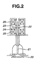
- FIG. 2 schematically shows a solenoid (electromagnetic) valve actuator for intake or exhaust valves 5 or 6.
- a valve element 20 is attached to one end of a valve stem 21.
- a plate-shaped movable member 22 is attached to valve stem 21.
- Movable member 22 is normally held at a neutral position by springs 23 and 24.
- An opening solenoid (electromagnetic coil) 25 is disposed below movable member 22, and a closing solenoid (electromagnetic coil) 26 is above movable member 22.
- movable member 22 Before a start of engine 1, movable member 22 is operated to oscillate resonantly by energizing opening and closing solenoids 25 and 26 alternately. When the amplitude is increased sufficiently, movable member 22 is attracted and held by one of the solenoids 25 and 26.
- valve element 20 is lifted from a valve seat and the valve is opened.
- valve element 20 is seated on the valve seat and the valve is closed.
- an air flowmeter 14 for sensing an intake air quantity there is provided, in intake passage 7, an air flowmeter 14 for sensing an intake air quantity, and a throttle valve 15 whose opening degree is controlled electronically.
- a solenoid type fuel injector 9 is provided in the intake port for each cylinder.
- a control unit (C/U) 10 controls intake and exhaust valves 5 and 6, throttle valve 15, fuel injectors 9 and spark plugs 4, in accordance with input information on engine operating conditions collected by various sensors.
- a crank angle sensor 11 produces a crank angle signal in synchronism with the engine revolution.
- An engine speed (rpm) can be determined from the crank angle signal.
- An accelerator pedal sensor 12 is arranged to sense an accelerator opening (or accelerator pedal depression degree). The signals of these sensors are inputted to control unit 10 serving as a main component of a controller in the control system.
- this control system controls the actual intake air quantity so as to achieve a target torque mainly by controlling the closing timing of intake valve 5. Moreover, to reduce exhaust emissions, especially the amount of NOx, this control system further controls the closing timing of exhaust valve 6, and the opening timing of intake valve 5 (and the opening timing of exhaust valve 6) to control the internal EGR quantity to an adequate level in accordance with engine operating conditions. In practice, however, the internal EGR quantity is affected not only by these valve timings but other factors as well. Therefore, this control system is arranged to estimate the internal EGR quantity in accordance with engine operating conditions, and to adjust the closing timing of intake valve 5 (of each cylinder, to be exact) in accordance with the estimated internal EGR quantity.
- the control system determines the intake air quantity in accordance with sensed values supplied from various sensors, and controls the fuel injection quantity of fuel injector 9 (of each cylinder, to be exact) in accordance with the intake air quantity.
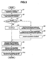
- FIG. 3 shows a main routine for controlling the intake valve closing timing according to the embodiment of the present invention.
- Step S1 is a step for reading the accelerator opening sensed by accelerator pedal sensor 12, the engine speed sensed by crank angle sensor 11 etc., and for calculating a target air quantity FQH0EM adequate for a demanded torque.
- Step S2 calculates a base internal EGR quantity EVEGR0 representing the internal EGR quantity in the non-overlap state in which there is no valve overlap of intake and exhaust valves. This calculation is carried out by following a subroutine shown in FIG. 4.
- control unit 10 reads an engine speed Ne and a target exhaust valve closing timing EVC.
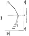
- control unit 10 calculates base internal EGR quantity EVEGR0, as EGR rate with respect to target air quantity FQH0EM, at step S23, by lookup from a map table prepared from characteristic data as shown in FIG. 7.
- Base internal EGR quantity EVEGR0 is a quantity of burned gases remaining in a cylinder in the non-overlap state in which there is no overlap of the intake and exhaust valves. Accordingly, as the cylinder volume determined by the piston position at the exhaust valve closure timing EVC becomes smaller, base internal EGR quantity EVEGR0 decreases.
- Base internal EGR quantity EVEGR0 becomes smallest at top dead center, as shown in FIG. 7.
- base internal EGR quantity EVEGRO differs between the condition before top dead center (BTDC) and the condition after top dead center (ATDC).
- BTDC condition before top dead center
- ATDC condition after top dead center
- EVC is before top dead center
- the exhaust valve is closed in the state the residual gas mixture is somewhat compressed.
- EVC is after top dead center
- the exhaust valve is closed in the state pulling back the exhaust gases discharged into the exhaust passage, and, due to a delay in return of the exhaust gases, the residual gas quantity, that is the internal EGR quantity, becomes smaller.
- this tendency is attributable to the inertia, and affected by engine speed Ne, too.
- base EGR quantity EVEGR0 is increased as the extent of separation (such as an angular distance in terms of degrees in crank shaft rotation) of EVC from exhaust TDC (that is, TDC on the exhaust stroke) becomes larger.
- Base EGR quantity EVEGR0 is increased with increase in engine speed Ne on the BTDC side, and base EGR quantity EVEGR0 is decreased with increase in engine speed Ne on the ATDC side.
- the rate of decrease of base EGR quantity EVEGR0 with respect to increase in engine speed Ne on the ATDC side is greater than the rate of increase of base EGR quantity EVEGR0 with respect to increase in engine speed Ne on the BTDC side.
- step S3 is for examining whether there is a valve overlap between target opening timing IVO of intake valve 5 and target closing timing EVC of exhaust valve 6.
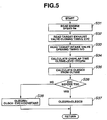
- control unit 10 proceeds from step S3 to step S5, and calculates a base overlap correction quantity OLEGR0 by a subroutine shown in FIG. 5.
- control unit 10 reads engine speed Ne, target exhaust valve closing timing EVC of exhaust valve 6 and intake valve opening timing IVO of intake valve 5.
- control unit 10 converts a valve overlap quantity (expressed in degrees of crankshaft rotation) to a valve overlap time OLTIME by using the input values of Ne, EVC and IVO according to the following equation.
- OLTIME (EVC-IVO)/Ne
- control unit 10 determines an intermediate quantity OLEGC0 from valve overlap time OLTIME by lookup from a map table.
- step 35 determines a value of quantity (intermediate quantity) OLEGC0 corresponding to the current value of valve overlap time OLTIME.
- the intermediate quantity OLEGC0 is increased monotonically with increase in valve overlap time OLTIME, as shown in FIG. 10.
- control unit 10 examines whether exhaust valve closing timing EVC is on the BTDC side or on the ATDC side.
- control unit 12 proceeds from step S36 to step S38, and determines base overlap (increase) correction quantity OLEGR0 by modifying the obtained value of OLEGC0 in accordance with target closing timing EVC by the following equation.
- OLEGR0 OLEGC0-EVC(retard quantity after TDC) ⁇ constant
- the variation quantity (or increase quantity) of the internal EGR between the base internal EGR quantity in the non-overlap state and the internal EGR quantity in the valve overlap state varies, even for the same valve overlap quantity (or time), since the influence of back-flow differs in dependence on exhaust valve closing timing EVC.
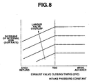
- FIG. 8 shows variation of the increase quantity of the internal EGR quantity with respect to EVC for different values of the overlap quantity (time) on the condition that engine speed Ne is constant and the intake pressure is constant.
- EVC When EVC is judged to be before TDC, the internal EGR increase quantity (OLEGR0) is held approximately constant irrespective of changes in EVC, as shown in FIG. 8.
- OBEGR0 the internal EGR increase quantity
- burned gases in the cylinder tend to be sucked back into the intake port on the lower pressure side during the valve overlap, rather than being expelled into the exhaust port, and the backward flow becomes dominant. Then, the burned gases of the back-flow to the intake port are sucked again into the cylinder in the subsequent intake stroke, so that the EGR rate is approximately constant. Therefore, the correction by EVC (the advance quantity before top dead center) is not performed at step S37.
- step 38 performs the subtraction by the subtrahend proportional to EVC (the retard quantity after TDC).
- step S6 calculates an intake pressure modification coefficient OLEGCB for modifying the thus-calculated base overlap correction quantity OLEGR0 in accordance with the intake pressure (boost pressure).
- Base overlap correction quantity OLEGR0 is calculated as an increase quantity of the internal EGR quantity due to a valve overlap under the condition where the intake pressure is constant (-50 mmHg). Even for the same overlap quantity (or time) and EVC, the exhaust back-flow quantity is varied by a variation in the intake pressure. This is taken into account by modification based on the intake pressure. In the case where there is provided no throttle valve, and the intake pressure is held approximately constant at the atmospheric pressure, the modification can be omitted.
- the modification based on the intake pressure is needed or desired when the intake pressure is controlled at a predetermined level by throttling the opening degree of throttle valve 15, to supply the vacuum pressure for braking, or for the suction of evaporative fuel vapor and blow-by gas into the intake system, and the intake air quantity is controlled by controlling the intake valve closing timing in consideration of the intake pressure.
- Intake pressure modification coefficient OLEGCB is calculated by a subroutine shown in FIG. 6.
- Step S41 reads the target intake pressure calculated by the above-mentioned intake pressure control process of controlling the intake pressure by controlling the throttle opening degree.
- Step S42 reads target closing timing EVC of exhaust valve 6.
- step S43 obtains a value of intake pressure modification coefficient OLEGCB by lookup from a map table prepared on the basis of characteristic data, as shown in FIG. 9.
- FIG. 9 shows a magnification (or multiplying factor) which is a ratio of the internal EGR increase quantity under the condition of intake pressure (negative pressure) being equal to -100 mmHg or -300 mmHg to the internal EGR increase quantity under the condition of intake pressure being equal to -50 mmHg.
- control system of this example increases the modification quantity OLEGCB as an absolute value of the intake pressure increases on the negative side, and increases the modification quantity OLEGCB in accordance with the retard quantity or angle of the exhaust valve closing timing EVC from the exhaust top dead center when the exhaust valve closing timing EVC is after the exhaust top dead center and the absolute value of the intake pressure is higher than a predetermined level which, in this example, is about -100 mmHg as seen from FIG. 9.
- Step S8 calculates estimated internal EGR quantity EGRREM by addition of overlap correction quantity OLEGR1 calculated at step S7, to base internal EGR quantity EVEGR0 calculated at step S2.
- the internal EGR quantity is estimated by adding the calculated overlap increase correction quantity OLEGR1 to base internal EGR quantity EVEGR0.
- EGRREM EVEGR0+OLEGR1
- Step S9 calculates a modified target air quantity HQH0FM by modifying target air quantity FQH0EM calculated at step S1, in accordance with estimated internal EGR quantity EGRREM.
- HQH0FM FQH0EM ⁇ (1+EGRREM)
- This modification is not intended to change the target air quantity per se, but it is a modification for convenience to take account of changes in the intake valve closing timing required to obtain the target air quantity (the quantity of fresh air) caused by the internal EGR quantity.
- the target air quantity is calculated as a total amount of gases in the cylinder by adding the quantity of the internal EGR gas to the target air quantity.
- Step S10 calculates target closing timing IVC of intake valve 5 in accordance with modified target air quantity HQH0FM.
- control unit delivers a valve control signal corresponding to target intake valve closing timing IVC, to the above-mentioned electromagnetic drive unit, and thereby controls intake valve 5 so that intake valve 5 is closed at target intake valve closing timing IVC.
- This control system estimates the internal EGR quantity in accordance with engine operating conditions accurately by taking account of valve overlap period, and controls the actual intake valve closing timing by modifying the target intake valve closing timing in accordance with the estimated internal EGR quantity. Therefore, the control system can obtain a quantity of fresh air suited to the target intake air quantity and control the torque accurately.
- FIGS. 11 ⁇ 17 shows a second embodiment of the present invention.
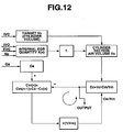
- FIG. 12 shows an engine cylinder intake air quantity estimating system according to the second embodiment. This estimating system is designed to accurately estimate an engine cylinder intake air quantity based on the internal EGR quantity calculated according to the estimating method of steps S1 ⁇ S8 shown in FIG. 3.
- An engine system shown in FIG. 11 is substantially identical to the engine system shown in FIG. 1, so that repetitive explanation is omitted.
- the fuel injection quantity by the fuel injector 9 is controlled basically in accordance with the intake air quantity (mass flow rate) Qa measured by air flowmeter 14, so as to achieve a desired air fuel ratio with respect to a cylinder intake air quantity (the mass of air in cylinder section) Cc calculated as explained below.
- intake air quantity (mass flow rate) Qa (Kg/h) measured by air flowmeter 14 shown in FIG. 11 is multiplied by 1/3600 and treated as (g/msec).
- a pressure is Pm (Pa), a volume is Vm (m 3 , constant), an air mass quantity (the mass of air) is Cm (g), and a temperature is Tm (K).
- a pressure is Pc (Pa)
- a volume is Vc (m 3 )
- an air mass quantity is Cc (g)
- a temperature is Tc (K).
- a cylinder fresh air rate is ⁇ (%).
- Pm Pc
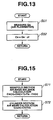
- FIG. 13 shows a routine for calculating an intake manifold section inflow air quantity, performed at regular time intervals of a predetermined time ⁇ t (1 msec, in this example).
- Step S51 is a step to measure the intake air quantity Qa (mass flow rate; g/msec) from the output of air flowmeter 9.
- Step S52 is to calculate a manifold inflow air quantity Ca (the mass (g) of air flowing into intake manifold section 101 during each predetermined time period ⁇ t by integration of intake air quantity Qa.
- Ca Qa• ⁇ t
- FIG. 14 shows a routine for calculating a cylinder section air volume quantity (the volume of air in cylinder section 102), performed at regular time intervals of the predetermined time ⁇ t.
- Step S61 detects a closing timing IVC of intake valve 5, an opening timing IVO of intake valve 5 and a closing timing EVC of exhaust valve 6. It is optional to employ lift sensors for directly sensing the valve opening or closing timing for intake and exhaust valves 5 and 6. However, it is possible to simplify the estimating system by employing target valve timings (command values) used in control unit 10 for the engine control as in the first embodiment.
- Step S62 uses the intake valve closing timing IVC and calculates a cylinder volume at that time from the intake valve closing timing IVC of intake valve 5.
- the thus-calculated cylinder volume is treated as a target Vc (m 3 ).
- Step S63 calculates an estimated internal EGR quantity X(v) (corresponding to the before-mentioned estimated internal EGR quantity EGRREM) in accordance with intake valve opening timing IVO of intake valve 5, exhaust valve closing timing EVC of exhaust valve 6 and engine revolution speed Ne, according to the estimating method explained in the first embodiment.
- the overlap quantity is determined by intake valve opening timing IVO and exhaust valve closing timing EVC, and the residual gas quantity (i.e., the internal EGR quantity) increases as the overlap quantity increases. Therefore, this estimating system calculates the cylinder fresh air rate ⁇ according to the above equation based on the overlap quantity.
- the internal EGR quantity is freely controlled by control of the valve overlap quantity, so that there is provided no EGR apparatus (for external EGR) in general.
- the residual gas quantity is set equal to a sum of the internal EGR quantity and an external EGR quantity of the EGR apparatus, and the cylinder fresh air rate ⁇ is calculated by using the sum of the internal and external EGR quantities.
- Step S66 calculates a Vc variation speed (volume flow rate; m 3 /msec) by multiplying the actual Vc (m 3 ) by engine speed Ne (rpm).
- Vc variation speed actual Vc•Ne•K
- K is a constant for adjusting units
- K (1/30) ⁇ (1/1000) where 1/30 is for conversion from Ne (rpm) to Ne (180 deg/sec), and 1/1000 is for conversion from Vc (m 3 /sec) to Vc (m 3 /msec).
- Vc variation speed actual Vc•Ne•K•n/N
- n/N an operating ratio
- N the number of the cylinders
- n the number of cylinders held in operation.
- n/N is equal to 3/4.
- Step S67 calculates a cylinder section air volume quantity Vc which is the quantity of air inducted into the cylinder section per unit time (1 msec), by integration of the Vc variation speed (or the rate of change of Vc).
- cylinder section air volume quantity Vc (m 3 ) Vc variation speed• ⁇ t.
- FIG. 15 shows a routine for continuous (or iterative) calculation (intake manifold section intake air balance calculation and cylinder section air mass quantity calculation), performed repeatedly at regular time intervals of the predetermined time ⁇ t.
- Step S71 is a step for manifold section intake air balance calculation (to determine a manifold section air mass quantity Cm).
- Step S72 is a step for calculation of the cylinder intake air quantity (cylinder section air mass quantity Cc).
- the estimating system can determine the cylinder section air mass quantity Cc (g) which is the cylinder intake air quantity, by performing steps S71 and 72 repeatedly as shown by a circular arrow indicating continuous calculation in FIG. 12, and output the thus-determined cylinder section air mass quantity Cc (g) as an output signal.
- the order of steps S71 and S72 can be reversed. In this case, the estimating system performs step S72 first, and then performs step S71 after step S72.
- Fig. 16 shows an aftertreatment routine.
- Step S81 performs a process of weighted average on the cylinder section air mass quantity Cc (g), expressed by the following equation, and thereby determines Cck (g).
- Cck Cck ⁇ (1-M) + Cc ⁇ M where M is a weight constant factor, and 0 ⁇ M ⁇ 1.
- Step S82 converts the thus-determined cylinder section air mass quantity Cck (g) to a per-cycle cylinder section air mass quantity Cck (g/cycle) by using engine speed Ne (rpm) to adapt the air mass quantity Cck to the cycle period.
- Cck (g/cycle) Cck/(120/Ne)
- step 582 converts the cylinder section air mass quantity Cck (g) to the per-cycle cylinder section air mass quantity Cck g/cycle) as in step S82 of FIG. 16. If the variation quantity ⁇ Cc is outside the predetermined region, step S81 performs the weight averaging operation as in step S81 of Fig. 16, and the routine proceeds to step S82 as in FIG. 16.
- the cylinder intake air estimating system can calculate the cylinder intake air quantity (cylinder section air mass quantity Cc or Cck) accurately by using the estimated internal EGR quantity in the continuous calculation of manifold section air mass balance calculation and cylinder section air mass calculation. Therefore, this estimating system can improve the calculation accuracy or estimation accuracy significantly in determining the cylinder intake air quantity in an engine of variable valve timing control type. As a result, a fuel injection quantity control system can improve the control accuracy of the air fuel ratio and thereby improve the exhaust performance and drivability significantly.
- This estimating method requires no pressure sensors and no temperature sensors. Therefore, the cylinder intake air quantity is estimated accurately without increasing the const.
- Fig. 18 is a control block diagram showing a third embodiment.
- a system shown in FIG. 18 is a control system for estimating an internal EGR quantity and controlling an ignition timing of an engine for a vehicle by using the result of the estimation.
- a first section of the ignition timing control system of FIG. 18 is an internal EGR quantity calculating section for calculating an estimated internal EGR quantity X(v) in accordance with exhaust valve closing timing EVC, intake valve opening timing IVO and engine revolution speed Ne in the same manner as in the preceding embodiments.
- the residual gas (mass) quantity X(g) is determined by conversion from a residual gas (volume) quantity by using the density p of the EGR gas.
- the residual gas (volume) quantity is equal to a sum of the estimated internal EGR quantity and the external EGR quantity when the external EGR is employed.
- the cylinder total gas (mass) quantity is determined by adding the cylinder section air (mass) quantity Cc(g) calculated as in the second embodiment, to the residual gas (mass) quantity X(g).
- a third section is a combustion speed calculating section for calculating a combustion speed (or burning velocity) Bv in accordance with the residual gas ratio ⁇ .
- the combustion speed Bv decreases as the residual gas ratio ⁇ increases.
- a fourth section is a combustion reaction time calculating section for calculating a combustion reaction time Bt in accordance with the combustion speed Bv.
- the combustion reaction time Bt is a time from the ignition timing until a peak of the combustion pressure is reached.
- a fifth section is a MBT calculating section for calculating MBT (maximum torque producing ignition timing) in accordance with the combustion reaction time Bt.
- the combustion reaction time Bt is converted to a crank angle interval by using the engine revolution speed Ne.
- the MBT is determined so as to achieve a combustion pressure peak at a predetermined crank angle position slightly retarded after the compression top dead center.
- the MBT is set at a crank angle position advanced from the predetermined crank angle position for the combustion pressure peak, by the crank angular interval corresponding to the combustion reaction time Bt.
- this ignition timing control system can estimate the combustion speed accurately in accordance with the internal EGR quantity, determine MBT accurately even in a transient state, provide optimum ignition timing control performance, and thereby improve the fuel consumption.
- engine 1 is a prime mover of a motor vehicle
- control unit 10 includes, as a main component, at least one onboard computer.
Landscapes
- Engineering & Computer Science (AREA)
- Chemical & Material Sciences (AREA)
- Combustion & Propulsion (AREA)
- Mechanical Engineering (AREA)
- General Engineering & Computer Science (AREA)
- Output Control And Ontrol Of Special Type Engine (AREA)
- Combined Controls Of Internal Combustion Engines (AREA)
Applications Claiming Priority (2)
| Application Number | Priority Date | Filing Date | Title |
|---|---|---|---|
| JP2000367770 | 2000-12-01 | ||
| JP2000367770A JP3959957B2 (ja) | 1999-12-03 | 2000-12-01 | エンジンの内部egr量推定方法と、該内部egr量推定値を用いた可変動弁制御方法、シリンダ吸入空気量算出方法および点火時期制御方法 |
Publications (3)
| Publication Number | Publication Date |
|---|---|
| EP1211402A2 true EP1211402A2 (fr) | 2002-06-05 |
| EP1211402A3 EP1211402A3 (fr) | 2002-09-11 |
| EP1211402B1 EP1211402B1 (fr) | 2007-05-16 |
Family
ID=18838134
Family Applications (1)
| Application Number | Title | Priority Date | Filing Date |
|---|---|---|---|
| EP01116955A Expired - Lifetime EP1211402B1 (fr) | 2000-12-01 | 2001-07-11 | Estimation de la quantité d'EGR interne pour la commande des soupapes et de l'allumage |
Country Status (2)
| Country | Link |
|---|---|
| EP (1) | EP1211402B1 (fr) |
| DE (1) | DE60128438T2 (fr) |
Cited By (7)
| Publication number | Priority date | Publication date | Assignee | Title |
|---|---|---|---|---|
| US6840235B2 (en) * | 2002-09-19 | 2005-01-11 | Nissan Motor Co., Ltd. | Internal exhaust gas recirculation amount estimation system of internal combustion engines |
| EP1452708A3 (fr) * | 2003-02-19 | 2005-02-02 | Toyota Jidosha Kabushiki Kaisha | Dispositif de commande d'un moteur à combustion interne |
| EP1734239A3 (fr) * | 2005-06-17 | 2007-04-04 | HONDA MOTOR CO., Ltd. | Dispositif de commande d'un moteur à combustion interne |
| EP1450023A3 (fr) * | 2003-02-19 | 2009-03-04 | Toyota Jidosha Kabushiki Kaisha | Dispositif et méthode pour estimer la quantité interne de gaz d'échappement recirculée dans un moteur à combustion interne |
| FR2989114A1 (fr) * | 2012-04-04 | 2013-10-11 | Peugeot Citroen Automobiles Sa | Procede de controle d'un moteur a combustion interne, systeme pour la mise en oeuvre du procede et vehicule automobile equipe d'un tel systeme |
| EP2527630A3 (fr) * | 2000-12-12 | 2014-07-23 | Toyota Jidosha Kabushiki Kaisha | Appareil de commande pour un moteur à combustion interne à commande de soupape variable |
| CN109519286A (zh) * | 2017-09-18 | 2019-03-26 | 现代自动车株式会社 | 用于计算包括连续可变气门持续时间装置的发动机的内部egr量的装置和方法 |
Families Citing this family (2)
| Publication number | Priority date | Publication date | Assignee | Title |
|---|---|---|---|---|
| JP5844227B2 (ja) | 2012-07-17 | 2016-01-13 | 本田技研工業株式会社 | 内燃機関の掃気ガス量算出装置および内部egr量算出装置 |
| EP4183997A1 (fr) * | 2021-11-18 | 2023-05-24 | Scania CV AB | Procédé de commande d'un moteur à combustion interne, agencement de commande, moteur à combustion interne et véhicule |
Family Cites Families (6)
| Publication number | Priority date | Publication date | Assignee | Title |
|---|---|---|---|---|
| US3714932A (en) * | 1971-08-19 | 1973-02-06 | Eaton Yale & Towne | Emissions control system |
| DE4325902C2 (de) * | 1993-08-02 | 1999-12-02 | Bosch Gmbh Robert | Verfahren zur Berechnung der Luftfüllung für eine Brennkraftmaschine mit variabler Gaswechselsteuerung |
| JP3085181B2 (ja) * | 1996-01-30 | 2000-09-04 | トヨタ自動車株式会社 | 内燃機関の点火時期制御装置 |
| JPH1037727A (ja) * | 1996-07-24 | 1998-02-10 | Fuji Heavy Ind Ltd | 多気筒エンジンの吸・排気弁制御装置及びその制御方法 |
| DE19753969B4 (de) * | 1997-12-05 | 2008-04-10 | Robert Bosch Gmbh | Verfahren und Vorrichtung zum Betreiben einer Brennkraftmaschine |
| DE60031074T2 (de) * | 1999-12-03 | 2007-02-15 | Nissan Motor Co., Ltd., Yokohama | Variable Ventilsteuerung für eine Brennkraftmaschine |
-
2001
- 2001-07-11 EP EP01116955A patent/EP1211402B1/fr not_active Expired - Lifetime
- 2001-07-11 DE DE60128438T patent/DE60128438T2/de not_active Expired - Lifetime
Cited By (11)
| Publication number | Priority date | Publication date | Assignee | Title |
|---|---|---|---|---|
| EP2527630A3 (fr) * | 2000-12-12 | 2014-07-23 | Toyota Jidosha Kabushiki Kaisha | Appareil de commande pour un moteur à combustion interne à commande de soupape variable |
| US6840235B2 (en) * | 2002-09-19 | 2005-01-11 | Nissan Motor Co., Ltd. | Internal exhaust gas recirculation amount estimation system of internal combustion engines |
| EP1452708A3 (fr) * | 2003-02-19 | 2005-02-02 | Toyota Jidosha Kabushiki Kaisha | Dispositif de commande d'un moteur à combustion interne |
| US6917874B2 (en) | 2003-02-19 | 2005-07-12 | Toyota Jidosha Kabushiki Kaisha | Apparatus for controlling internal combustion engine |
| EP1450023A3 (fr) * | 2003-02-19 | 2009-03-04 | Toyota Jidosha Kabushiki Kaisha | Dispositif et méthode pour estimer la quantité interne de gaz d'échappement recirculée dans un moteur à combustion interne |
| EP1734239A3 (fr) * | 2005-06-17 | 2007-04-04 | HONDA MOTOR CO., Ltd. | Dispositif de commande d'un moteur à combustion interne |
| US7314028B2 (en) | 2005-06-17 | 2008-01-01 | Honda Motor Co., Ltd. | Control apparatus for internal combustion engine |
| EP2189641A1 (fr) * | 2005-06-17 | 2010-05-26 | Honda Motor Co., Ltd | Dispositif de commande d'un moteur à combustion interne |
| FR2989114A1 (fr) * | 2012-04-04 | 2013-10-11 | Peugeot Citroen Automobiles Sa | Procede de controle d'un moteur a combustion interne, systeme pour la mise en oeuvre du procede et vehicule automobile equipe d'un tel systeme |
| CN109519286A (zh) * | 2017-09-18 | 2019-03-26 | 现代自动车株式会社 | 用于计算包括连续可变气门持续时间装置的发动机的内部egr量的装置和方法 |
| CN109519286B (zh) * | 2017-09-18 | 2022-05-24 | 现代自动车株式会社 | 用于计算包括连续可变气门持续时间装置的发动机的内部egr量的装置和方法 |
Also Published As
| Publication number | Publication date |
|---|---|
| EP1211402A3 (fr) | 2002-09-11 |
| DE60128438T2 (de) | 2007-09-06 |
| EP1211402B1 (fr) | 2007-05-16 |
| DE60128438D1 (de) | 2007-06-28 |
Similar Documents
| Publication | Publication Date | Title |
|---|---|---|
| US6827051B2 (en) | Internal EGR quantity estimation, cylinder intake air quantity calculation, valve timing control, and ignition timing control | |
| US6412458B2 (en) | Valve timing control for engine | |
| US6328007B1 (en) | Internal cylinder intake-air quantity calculating apparatus and method for variable valve open/closure timing controlled engine | |
| JP3747700B2 (ja) | 可変動弁エンジンの吸入空気量算出装置 | |
| JP3637825B2 (ja) | 可変動弁エンジンの制御装置 | |
| US20120290195A1 (en) | Control system for internal combustion engine | |
| JP3959957B2 (ja) | エンジンの内部egr量推定方法と、該内部egr量推定値を用いた可変動弁制御方法、シリンダ吸入空気量算出方法および点火時期制御方法 | |
| EP1211402B1 (fr) | Estimation de la quantité d'EGR interne pour la commande des soupapes et de l'allumage | |
| US7357127B2 (en) | Method for determining the air mass in a cylinder | |
| JP3622538B2 (ja) | エンジンの吸入空気量検出装置 | |
| US6986330B2 (en) | Internal combustion engine having variable valve actuation device and method of calculating intake amount in the same internal combustion engine | |
| JP3614060B2 (ja) | 可変動弁エンジンの点火時期制御装置 | |
| JP2001280228A (ja) | 可変動弁エンジンの点火時期制御装置 | |
| JP2002227687A (ja) | エンジンの内部egr率推定装置 | |
| JP2021050632A (ja) | 内燃機関の制御装置 | |
| JP3807173B2 (ja) | 可変動弁エンジンの吸入空気量検出装置及び燃料噴射制御装置 | |
| JP3799833B2 (ja) | 可変動弁エンジンのシリンダ吸入空気量検出装置 | |
| JP3915367B2 (ja) | 可変動弁エンジンの制御装置 | |
| JP3800828B2 (ja) | 可変動弁エンジンのシリンダ内残ガス量検出装置 | |
| JP3620381B2 (ja) | 可変動弁エンジンの制御装置 | |
| JP3885456B2 (ja) | 可変動弁の制御装置 | |
| JP3565119B2 (ja) | 可変動弁の制御装置 | |
| JP4144985B2 (ja) | 可変動弁エンジンの制御装置 | |
| JP3758448B2 (ja) | 可変動弁エンジンの制御装置 | |
| KR100764495B1 (ko) | 내연기관의 가변 밸브 타이밍 제어 방법 및 그 시스템 |
Legal Events
| Date | Code | Title | Description |
|---|---|---|---|
| PUAI | Public reference made under article 153(3) epc to a published international application that has entered the european phase |
Free format text: ORIGINAL CODE: 0009012 |
|
| 17P | Request for examination filed |
Effective date: 20010711 |
|
| AK | Designated contracting states |
Kind code of ref document: A2 Designated state(s): AT BE CH CY DE DK ES FI FR GB GR IE IT LI LU MC NL PT SE TR |
|
| AX | Request for extension of the european patent |
Free format text: AL;LT;LV;MK;RO;SI |
|
| PUAL | Search report despatched |
Free format text: ORIGINAL CODE: 0009013 |
|
| AK | Designated contracting states |
Kind code of ref document: A3 Designated state(s): AT BE CH CY DE DK ES FI FR GB GR IE IT LI LU MC NL PT SE TR |
|
| AX | Request for extension of the european patent |
Free format text: AL;LT;LV;MK;RO;SI |
|
| AKX | Designation fees paid |
Designated state(s): DE FR GB |
|
| RIN1 | Information on inventor provided before grant (corrected) |
Inventor name: ARAI, MASAHIRO Inventor name: KAWASAKI, TAKAO |
|
| GRAP | Despatch of communication of intention to grant a patent |
Free format text: ORIGINAL CODE: EPIDOSNIGR1 |
|
| GRAS | Grant fee paid |
Free format text: ORIGINAL CODE: EPIDOSNIGR3 |
|
| GRAA | (expected) grant |
Free format text: ORIGINAL CODE: 0009210 |
|
| AK | Designated contracting states |
Kind code of ref document: B1 Designated state(s): DE FR GB |
|
| REG | Reference to a national code |
Ref country code: GB Ref legal event code: FG4D |
|
| REF | Corresponds to: |
Ref document number: 60128438 Country of ref document: DE Date of ref document: 20070628 Kind code of ref document: P |
|
| ET | Fr: translation filed | ||
| PLBE | No opposition filed within time limit |
Free format text: ORIGINAL CODE: 0009261 |
|
| STAA | Information on the status of an ep patent application or granted ep patent |
Free format text: STATUS: NO OPPOSITION FILED WITHIN TIME LIMIT |
|
| 26N | No opposition filed |
Effective date: 20080219 |
|
| PGFP | Annual fee paid to national office [announced via postgrant information from national office to epo] |
Ref country code: FR Payment date: 20110727 Year of fee payment: 11 |
|
| PGFP | Annual fee paid to national office [announced via postgrant information from national office to epo] |
Ref country code: GB Payment date: 20110706 Year of fee payment: 11 Ref country code: DE Payment date: 20110706 Year of fee payment: 11 |
|
| GBPC | Gb: european patent ceased through non-payment of renewal fee |
Effective date: 20120711 |
|
| REG | Reference to a national code |
Ref country code: FR Ref legal event code: ST Effective date: 20130329 |
|
| PG25 | Lapsed in a contracting state [announced via postgrant information from national office to epo] |
Ref country code: GB Free format text: LAPSE BECAUSE OF NON-PAYMENT OF DUE FEES Effective date: 20120711 Ref country code: FR Free format text: LAPSE BECAUSE OF NON-PAYMENT OF DUE FEES Effective date: 20120731 Ref country code: DE Free format text: LAPSE BECAUSE OF NON-PAYMENT OF DUE FEES Effective date: 20130201 |
|
| REG | Reference to a national code |
Ref country code: DE Ref legal event code: R119 Ref document number: 60128438 Country of ref document: DE Effective date: 20130201 |