EP1211457A1 - Beleuchtungslichtquelle für Lichtleiter - Google Patents
Beleuchtungslichtquelle für Lichtleiter Download PDFInfo
- Publication number
- EP1211457A1 EP1211457A1 EP01309995A EP01309995A EP1211457A1 EP 1211457 A1 EP1211457 A1 EP 1211457A1 EP 01309995 A EP01309995 A EP 01309995A EP 01309995 A EP01309995 A EP 01309995A EP 1211457 A1 EP1211457 A1 EP 1211457A1
- Authority
- EP
- European Patent Office
- Prior art keywords
- light
- concave mirror
- illumination
- board
- light source
- Prior art date
- Legal status (The legal status is an assumption and is not a legal conclusion. Google has not performed a legal analysis and makes no representation as to the accuracy of the status listed.)
- Withdrawn
Links
- 238000005286 illumination Methods 0.000 title claims abstract description 80
- 230000003287 optical effect Effects 0.000 claims abstract description 46
- 239000013307 optical fiber Substances 0.000 claims abstract description 20
- 238000005520 cutting process Methods 0.000 claims description 8
- 238000004519 manufacturing process Methods 0.000 description 24
- 238000007689 inspection Methods 0.000 description 19
- 238000000034 method Methods 0.000 description 14
- 238000009434 installation Methods 0.000 description 12
- 229910052736 halogen Inorganic materials 0.000 description 6
- 150000002367 halogens Chemical class 0.000 description 6
- 238000003780 insertion Methods 0.000 description 5
- 230000037431 insertion Effects 0.000 description 5
- 229910052751 metal Inorganic materials 0.000 description 5
- 239000002184 metal Substances 0.000 description 5
- 230000004907 flux Effects 0.000 description 4
- 229910052782 aluminium Inorganic materials 0.000 description 3
- XAGFODPZIPBFFR-UHFFFAOYSA-N aluminium Chemical compound [Al] XAGFODPZIPBFFR-UHFFFAOYSA-N 0.000 description 3
- 238000001816 cooling Methods 0.000 description 3
- 238000000151 deposition Methods 0.000 description 3
- 239000011521 glass Substances 0.000 description 3
- 230000006872 improvement Effects 0.000 description 3
- 238000000465 moulding Methods 0.000 description 3
- 239000004065 semiconductor Substances 0.000 description 3
- 229910001369 Brass Inorganic materials 0.000 description 2
- 239000010951 brass Substances 0.000 description 2
- 239000003086 colorant Substances 0.000 description 2
- 230000007547 defect Effects 0.000 description 2
- 239000000463 material Substances 0.000 description 2
- 230000008569 process Effects 0.000 description 2
- 239000000047 product Substances 0.000 description 2
- 239000013589 supplement Substances 0.000 description 2
- 229920003002 synthetic resin Polymers 0.000 description 2
- 239000000057 synthetic resin Substances 0.000 description 2
- 239000004925 Acrylic resin Substances 0.000 description 1
- 229920000178 Acrylic resin Polymers 0.000 description 1
- BQCADISMDOOEFD-UHFFFAOYSA-N Silver Chemical compound [Ag] BQCADISMDOOEFD-UHFFFAOYSA-N 0.000 description 1
- 230000005856 abnormality Effects 0.000 description 1
- 238000005299 abrasion Methods 0.000 description 1
- 230000037237 body shape Effects 0.000 description 1
- 230000008859 change Effects 0.000 description 1
- 230000008021 deposition Effects 0.000 description 1
- 238000009792 diffusion process Methods 0.000 description 1
- 230000005611 electricity Effects 0.000 description 1
- PCHJSUWPFVWCPO-UHFFFAOYSA-N gold Chemical compound [Au] PCHJSUWPFVWCPO-UHFFFAOYSA-N 0.000 description 1
- 229910052737 gold Inorganic materials 0.000 description 1
- 239000010931 gold Substances 0.000 description 1
- 238000003384 imaging method Methods 0.000 description 1
- 230000001678 irradiating effect Effects 0.000 description 1
- 230000002093 peripheral effect Effects 0.000 description 1
- 238000005498 polishing Methods 0.000 description 1
- 238000003825 pressing Methods 0.000 description 1
- 230000009467 reduction Effects 0.000 description 1
- 239000011347 resin Substances 0.000 description 1
- 229920005989 resin Polymers 0.000 description 1
- 229910052709 silver Inorganic materials 0.000 description 1
- 239000004332 silver Substances 0.000 description 1
- 238000005476 soldering Methods 0.000 description 1
Images









Classifications
-
- H—ELECTRICITY
- H01—ELECTRIC ELEMENTS
- H01K—ELECTRIC INCANDESCENT LAMPS
- H01K7/00—Lamps for purposes other than general lighting
-
- G—PHYSICS
- G02—OPTICS
- G02B—OPTICAL ELEMENTS, SYSTEMS OR APPARATUS
- G02B6/00—Light guides; Structural details of arrangements comprising light guides and other optical elements, e.g. couplings
- G02B6/0001—Light guides; Structural details of arrangements comprising light guides and other optical elements, e.g. couplings specially adapted for lighting devices or systems
- G02B6/0005—Light guides; Structural details of arrangements comprising light guides and other optical elements, e.g. couplings specially adapted for lighting devices or systems the light guides being of the fibre type
- G02B6/0006—Coupling light into the fibre
Definitions
- the present invention relates to a light source of illumination for a light guide, which is used for inspection of e.g. qualities of industrial products on a production line, utilizing image-taking sensors such as CCD cameras, wherein the light guide is used to illuminate or light up image-taking spots . More particularly, it relates to a light source of illumination for a light guide using a light-emitting diode as the light source.
- a method for inspecting the quality of industrial products such as printed-circuit boards or semiconductors, for example, failure of soldering, defects, or attachment of foreign matters, on a production line a method utilizing the image-taking with a CCD camera, etc. has been spread.
- a specific spot of a component is subjected to the image-taking and this collected image is compared with normal image-taking results, whereby the presence or absence of abnormality is determined.
- it is required to illuminate or light up uniformly the image-taking site of the CCD camera with a lighting apparatus, and a light guide is used as a type of the lighting apparatus.
- the above light guide is a lighting apparatus which is obtained by bundling various optical fibers, and wherein the basal end portion of the bundle is used as a light-receiving portion, a light beam emitted from a light source is allowed to enter thereinto, the front end portion of the optical fibers as a light-irradiating portion is located toward a subject to be inspected, and a light beams from the front end portion of the optical fibers are irradiated over the subject to be inspected.
- the production line In a production line using the inspection method utilizing the image-taking with the CCD camera, when defects have occurred in the lighting apparatus and inspection becomes impossible, the production line must be stopped.
- halogen lamps are generally used.
- halogen lamps have a short lifetime of about 200 to 1,000 hours, and remarkable individual differences in the lifetime are observed. Accordingly, in the production line of e.g. semiconductors for which a few hundred light guides are used, there is a problem that operators are required to always monitor the production line so as to instantly change the burnt out lamp, to prevent the stoppage of the production line. Further, in a case where the lighting is switched on and off frequently during the inspection, the lifetime of the lamp of the halogen light source is remarkably lowered.
- the space in which the inspection apparatus is installed is limited.
- the installation space for the light guide using a halogen lamp is required to be large and this apparatus can not be installed in a narrow space.
- JP-A-11-219608 filed by the present inventors proposes a light source of illumination utilizing a light-emitting diode. Since the light-emitting diode has a long lifetime and replacement of lamp is no longer required, it is possible to proceed with labor saving or improvement of working efficiency by the production line. However, since the light emitted from a single light-emitting diode is faint, it can not be used as itself as the light source of illumination. Accordingly, in JP-A-11-219608, light beams of light-emitting diodes are collected with a light-condensing member to obtain sufficient light for lighting.
- a structure wherein light-emitting portions of plural light-emitting diodes are supported by a board so that the diodes face the same face side; a truncated light-condensing member made of a light-transmittable material is provided at the light-emitting portions so that an expanded bottom surface of the member is in contact with the light-emitting portions; and light beams emitted from the plural light-emitting diodes are collected to obtain sufficient luminosity for illumination.
- the quantity of light of the light-emitting diode is faint as compared with the halogen lamp, a lot of diodes are required to obtain sufficient quantity of light for illumination necessary for the inspection. Accordingly, there is also a problem that if various light-emitting diodes are disposed on one single board, the board itself becomes large and the apparatus can not be made compact.
- a light source of illumination for a light guide which comprises a plurality of light-emitting diodes supported by a board and arranged such that light-emitting portions of the diodes face the same side; a concave mirror for reflecting and collecting light beams emitted by the light-emitting diodes; and an optical connector having an optical fiber cable connected thereto, for introducing the light collected by the concave mirror; wherein the concave mirror is located at a position opposite to the light-emitting diodes, and the optical connector is located at a focal point of the concave mirror.
- the light beams emitted by the plural light-emitting diodes are reflected by the concave mirror and collected at the position at which the optical connector is located, whereby it is possible to efficiently introduce the light into the optical fiber cable of the light guide and obtain sufficient quantity of light.
- the light-emitting diodes since the light-emitting diodes usually have a long lifetime and replacement thereof is hardly required, labor-saving and improvement of working efficiency can be made in the production line. Moreover, even if the light-emitting diodes are frequently switched on and off in use,the lifetime may not be reduced.
- the color tone of the light-emitting diodes can be selected depending upon the purpose, whereby the precision of inspection or the like can be improved.
- the concave mirror used as the light-collecting means preferably has a simple structure, the production costs can be kept low and weight saving can be made. Since the light beams emitted from the light-emitting diode are reflected by the concave mirror and collected at the light-emitting diode side, the entire apparatus can be made compact as compared with the case where the light-collecting member is located in front of the light-emitting diode and collection of light beams is made at the further frontward position of the light-collecting member.
- a light-delivering hole is formed at the center of the board, and the light-emitting diodes are annularly arranged surrounding the light-delivering hole, and wherein the light beams reflected by the concave mirror are output to the optical connector through the light-delivering hole.
- light beams are transmitted to the optical connector through the light-delivering hole formed at the center of the board, whereby the board, concave mirror and optical connector can be coaxially located and the apparatus can be made compact.
- a hole is formed at the center of the concave mirror, another board is provided at the back face side of the concave mirror, another group of light-emitting diodes is supported by and arranged on the other board, and the light beams emitted from the other group of light-emitting diodes are directly output to the optical connector through the light-delivering hole of the board.
- the concave mirror is located slantwise relative to the optical axis of light beams emitted from the light-emitting diodes located opposite to the concave mirror, the light beams reflected by the concave mirror are collected at sideward point of the board located opposite to the concave mirror and the optical connector is located at the sideward point.
- the optical connector since the optical connector is located at the sideward point of the board, it is not required to form a light-delivering hole on the board. Accordingly, it is possible to locate the light-emitting diodes on the entire face of the board, and obtain an output light having a uniform luminance in the radial direction. Further, this embodiment is suitable for the case where the optical connector is required to be located slantwise due to the conditions such as the site on which the light source is installed.
- directions of the plural light-emitting diodes supported by the first mentioned board and/or the other board are adjusted so that the light beams emitted from the plural light-emitting diodes can be collected at a predetermined angle.
- the above embodiment it is possible to collect the light beams emitted from the light-emitting diodes at the initial stage and locate the concave mirror at a further closed position. Further, even in a case where a hole is formed at the center of the concave mirror and the light beams of the group of light-emitting diodes installed at the back face side of the concave mirror is output through this hole, by adjusting the directions of the light-emitting diodes so that the light beams emitted from the light-emitting diodes are collected at a predetermined angle, it is possible to enter the light efficiently into the optical connector.
- the concave mirror has a non-circular shape.
- the concave mirror since the concave mirror has a non-circular shape, the entire body of casing of the light source of illumination for a light guide can be made rectangular or oblong, it is possible to shorten the width direction of installation space, make the apparatus more compact, install the apparatus even in a narrow inspection space, and the like, whereby the installation space can be fully effectively used depending upon the shape of casing.
- the concave mirror has a shape obtained by cutting a circle along parallel straight lines each connecting opposite points on the circumference of the circle.
- the shape of the concave mirror can be formed in a rectangular or oblong shape or the like depending upon the shape of the casing, whereby the installation space can be fully effectively used depending upon the shape of the casing. Further, since the concave mirror may be obtained by a method in which both side portions of a circle are cut away, it is possible to commonise the production steps with those of usual circular concave mirrors and reduce the production cost of the concave mirror.
- the light-emitting diodes are arranged in plural steps on the board.
- the plural light-emitting diodes are arranged in at least two steps in a vertical direction or the like, it is possible to provide a large number of light-emitting diodes on the same board area, and increase the quantity of light by increasing the density of the arranged light-emitting diodes while keeping the apparatus small.
- a light source of illumination for a light guide which comprises: at least two light source units, each unit comprising a plurality of light-emitting diodes supported by a board and arranged such that light-emitting portions of the diodes face the same side, and a concave mirror for reflecting and collecting light beams emitted by the light-emitting diodes; a polyhedral reflection mirror which reflects light beams reflected by the respective concave mirrors of the at least two light source units and collects the light beams at one portion; and an optical connector having an optical fiber cable connected thereto, which is located at a position where the light is collected by the polyhedral reflection mirror.
- the light beams emitted from the plural light-emitting diodes of the reppective light source units are reflected by the concave mirror, and then reflected again by the polyhedral reflection mirror and collected at the optical connector, whereby it is possible to introduce the light efficiently into the optical fiber cable for the light guide connected to the optical connector and obtain sufficient quantity of light.
- the light-emitting diodes since the light-emitting diodes usually have a long lifetime and replacement thereof is hardly required, labor-saving and improvement of working efficiency can be made in the production line. Moreover, even if the light-emitting diodes are frequently switched on and off in use, the lifetime may not be reduced.
- the color tone of the light-emitting diodes can be selected depending upon the purpose, whereby the precision of inspection or the like can be improved.
- the concave mirror used as the light-collecting means preferably has a simple structure, the production cost can be kept low and weight saving can be made. Since the light beams collected by the at least two light source units are collected or concentrated at one portion by the polyhedral reflection mirror, the quantity of light can be increased.
- a light-delivering hole is formed at the center of the board, and the light-emitting diodes are annularly arranged surrounding the light-delivering hole, wherein the light beams reflected by the concave mirror are irradiated on the polyhedral reflection mirror through the light-delivering hole.
- light beams are irradiated on the polyhedral reflection mirror through the light-delivering hole formed at the center of the board, whereby the board, concave mirror and polyhedral reflection mirror can be coaxially located and the apparatus can be made compact.
- a hole is formed at the center of the concave mirror, another board is provided at the back face side of the concave mirror, another group of light-emitting diodes is supported by and arranged on this other board, and the light beams emitted from the other group of light-emitting diodes are directly irradiated on the polyhedral reflection mirror through the light-delivering hole of the board.
- the light-emitting diodes are arranged in plural steps on the board.
- the plural light-emitting diodes are arranged in at least two steps in a preferably vertical direction on the board, it is possible to provide a large number of light-emitting diodes on the same board area, and increase the quantity of light by increasing the density of the arranged light-emitting diodes while keeping the apparatus small.
- the concave mirror has a shape obtained by cutting a circle along parallel straight lines each connecting opposite points on the circumference of the circle.
- the shape of the concave mirror can be formed in a rectangular or oblong shape or the like depending upon the shape of the casing, whereby the installation space can be fully effectively used depending upon the shape of the casing.
- the concave mirror may be obtained by a method in which both side portions of a circle are cut out of, for example, a circular concave mirror, it is possible to commonise the production steps with those of usual circular concave mirrors and reduce the production cost of the concave mirror.
- respective faces of the polyhedral reflection mirror are constituted by a concave curved surface.
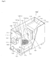
- Figs.1 to 8 show an embodiment of a light source of illumination for a light guide according to the present invention.
- Fig.1 is a perspective view showing a state wherein a part of a casing is cut away.
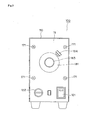
- Fig.2 is a front view of the light source of illumination.
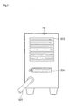
- Fig.3 is a rear view of the light source of illumination.
- Fig.4 is a front view of a first board.
- Fig.5 is a front view of a second board.
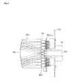
- Fig.6 is a side view of the second board.
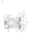
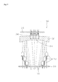
- Fig.7 is a side view wherein a main part of the light source of illumination is enlarged.
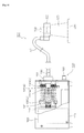
- Fig.8 is a partially cutaway side view showing a state wherein a light guide is connected to the light source of illumination.
- a light source of illumination 100 of the present invention has a box-like casing 110.
- a power supply circuit 120 is disposed at the rearward in the casing 110, and a cooling fan 160 is disposed at the forward lower portion in the casing with the fan face located upwardly.
- rod-like frames 170 are fixed with screws 171.
- a first board 130(a) supporting a first light-emitting diode group 131 is disposed such that the light-emitting portions of the first light-emitting diode group 131 face the back face 112 side, and the first light-emitting diode group 131 is supported by and fixed on the frames 170 via brackets not shown.
- the first board 130(a) has a circular light-delivering hole 132 at the central portion, and the first light-emitting diode groups 131 are annularly arranged surrounding the light-delivering hole 132.
- a concave mirror 150(a) having a hole 151 at the central portion is disposed opposite to the first light-emitting diode group 131 so that the concave face faces the front face 111 side, and the concave mirror is supported by and fixed on the frames 170 via brackets not shown.
- the concave mirror 150(a) ones obtained by abrasion processing of a metal such as brass or ones obtained by molding glass or a synthetic resin and depositing a metal on its surface, may be employed.
- a second board 140 supporting second light-emitting diode groups 141 is connected to and supported by the back face side of the concave mirror 150(a) such that the light-emitting portions of the second light-emitting diode groups 141 face the front face 111 side.
- the second light-emitting diode groups 141 are arranged in a circular form at the central portion of the second board 140.
- the second light-emitting diode groups 141 are arranged slantwise so that the emitted light beams are collected or focused on the focal point F of the concave mirror 150 (a) .
- the front end portion of the second light-emitting diode groups 141 is inserted into a hole 151 at the center of the concave mirror 150(a), and the light beams emitted from the second light-emitting diode groups 141 pass through the hole 151 and are collected on the focal point F of the concave mirror 150(a), as indicated by the imaginary line in Fig.7.
- a basal end portion of a cylindrical optical connector 181 which penetrates through the front face 111 and is inserted inwardly.
- the basal end portion of the cylindrical optical connector 181 is disposed at the front face 111 of the casing 110.
- the optical connector 181 has an insertion hole 183 into which an optical plug 182 of a light guide 300 as shown in Fig.8 is inserted.
- a power supply switch 121 and a selector of power output 122 are provided, and further the optical connector 181 is provided.
- a fixing screw 184 is screwed so as to fix the optical plug 182 inserted into the insertion hole 183 and prevent unwanted detachment.
- a vent hole 123 is formed to discharge the heat generated by the electric supply circuit 120 or the light-emitting diode groups 131, 141 out of the casing 110.
- a connector 124 for connecting it to a computer or the like is provided, and from the lower portion of the casing, an electric wire 125 for supplying electricity to the electric supply circuit 120 from the outside, extends.
- a light guide 300 has an optical fiber cable 310 obtained by bundling various optical fibers and covering them with a tube, an optical plug 182 provided at the basal end portion of this optical fiber cable 310, and an annular light-emitting portion 320 provided at the front end.
- a CCD camera 500 is inserted and arranged to face a workpiece 400 to be inspected.
- the optical plug 182 provided at the basal end of the optical fiber cable 310 of the light guide 300 is inserted into the insertion hole 183 of the optical connector 181, and the fixing screw 184 is firmly tightened to secure the connection.
- the annular light-emitting portion 320 of the light guide 300 is arranged to face the workpiece 400 to be inspected, and the CCD camera 500 is inserted into a central opening of the annular light-emitting portion 320 so as to take image on the inspection spots of the workpiece 400.
- the light guide 300 is transferred with a driving device not shown in accordance with an inspection process.
- a predetermined voltage is supplied from the power supply circuit 120 to the first light-emitting diode group 131 via the first board 130(a) , by which the first light-emitting diode group 131 emits light beams, and likewise, a predetermined voltage is supplied from the power supply circuit 120 to the second light-emitting diode group 141 via the second board 140, by which the second light-emitting diode group 141 emits light beams.
- the quantity of light may be controlled by the selector of power output 122 which is provided at the front face 111 of the casing 110. Further, the cooling fan 160 is operated so as to prevent overheat by heat evolution of the first light-emitting diode group 131 and the second light-emitting diode group 141, or the like.
- the light beams emitted from the first light-emitting diode group 131 are reflected by the concave mirror 150(a) and collected on the focal point F.
- the central portion of the output light collected on the focal point area tends to be darker than the peripheral portion thereof, only with the light beams of the first light-emitting diode group 131.
- the output light thus collected enters into the optical plug 182 provided at the basal end portion of the optical fiber cable 310 of the light guide 300, and is irradiated over the workpiece 400 to be inspected from the annular light-emitting portion 320 of the light guide 300 through the optical fiber cable 310.
- the inspection spots of the thus irradiated workpiece 400 are imaged by the CCD camera 500 for inspection.
- the concave mirror 150(a) since the light beams of plural light-emitting diodes are collected by use of the concave mirror 150(a), it is possible to generate sufficiently luminous light for the inspection of the workpiece 400. Since the lifetime of the light-emitting diode is long, replacement or the like of lamps is not required, and labor saving in the production line can be realized and at the same time, the working efficiency can be improved. Further, by using the concave mirror 150(a), the first light-emitting diode group 131 can be located at the output light side, whereby the space in the apparatus can be efficiently utilized and the entire apparatus can be made compact.
- Fig.9 shows the second embodiment of a light source of illumination for a light guide according to the present invention, and is a side view wherein a main part of the light source of illumination is enlarged.
- the same parts as in the previous embodiment are indicated by the same reference numerals and their explanations will be omitted.
- the transparent member 190 is made of a light-transmittable material such as glass or a transparent acrylic resin, and has a cylindrical shape as a whole and a convex curved surface formed at one end. On the surface of this convex curved surface, a metal film of e.g. gold, silver or aluminum is attached uniformly by deposition or the like to form a concave mirror 191. Further, the transparent member 190 is located such that a plane surface 192 of another end thereof is in contact with the light-emitting portion of the first light-emitting diode group 131.
- the light beams emitted from the first light-emitting diode group 131 enter through the plane surface 192 of the transparent member 190 and pass through the inside thereof, and then reflected by the concave mirror 191, pass through the inside of the transparent member 190 again, and are collected at the inside of the insertion hole 183 of the optical connector 181 inserted into the first board 130(a).
- the light beams emitted from the first light-emitting diode group 131 are introduced into the transparent member 190 and reflected by the concave mirror 191 formed at the end face of the transparent member 190, whereby the light can be introduced toward the concave mirror 191 while the loss of light due to the diffusion of light emitted from the light-emitting diode can be kept as low as possible, and the light-collecting efficiency can be improved.
- Fig.10 shows the third embodiment of a light source of illumination for a light guide according to the present invention, and is a side view wherein a main part of the light source of illumination is enlarged.
- the concave mirror 150 (a) is located slantwise relative to the optical axis of the light beams emitted by the first light-emitting diode group 131, and the light beams emitted from the first light-emitting diode group 131 are reflected by the concave mirror 150(a) and collected at a sideward point of the board 130(a) supporting the first light-emitting diode group 131.
- the optical connector 181 is located at the outside of the board 130(a) and at the position at which the concave mirror 150(a) focuses. Accordingly, on the board 130(a) , no hole is formed and the first light-emitting diode group 131 is circularly arranged without space.
- the optical connector 181 since there is no need to provide a light-transmittable portion at the center of the first light-emitting diode group 131, all elements of the first light-emitting diode group 131 can be arranged in a complete circular configuration. Accordingly, it is possible to generate a uniform and luminous output light from the optical connector without providing the second light-emitting diode group 141 in the previous embodiment. Further, this embodiment is preferred for the case where the optical connector 181 must be located at a slantwise angle due to the conditions of the site at which the light source is located.
- the light source of illumination of the present invention may have a structure wherein the light source is preliminarily connected to a light guide to form a lighting apparatus in which the light source is supported by frames integrated with the light guide.
- the light source of illumination and the light guide are integrated, and these are transferred together depending upon the portion to be inspected.
- no repeated flexural stress or the like is exerted on the optical fiber cable of the light guide, whereby it is possible to prevent breaking or the like of the optical fiber cable by flex fatigue.
- the light-emitting diode of a predetermined color by selecting the light-emitting diode of a predetermined color, lighting or illuminating beams of a color suitable for the purpose can be output.
- lighting or illuminating beams of a color suitable for the purpose can be output.
- by arranging light-emitting diodes of three colors i.e. RGB alternately and making only the light-emitting diodes for the desired color to emit it is possible to generate various colors by only one light source of illumination.
- Figs.11 to 15 show the fourth embodiment of the light source of illumination for the light guide according to the present invention.
- Fig.11 is a perspective view wherein a part of a casing of the light source of illumination is cut away.
- Fig.12 is a front view of a first board.
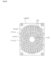
- Fig.13 is a front view of a concave mirror.
- Fig.14 is a side view wherein a main part of the light source of illumination is enlarged.
- Fig.15 is a partially cutaway side view showing a state wherein a light guide is connected to the light source of illumination.
- the light source of illumination 100' of the fourth embodiment is different from the first embodiment in that the light-emitting diode group 131 is arranged in two steps in the vertical direction on the surface of a board 130(b) as shown in Figs.11 and 12, and that a concave mirror 150(b) has a non-circular form and a configuration obtained by cutting a circle along parallel straight lines 152 each connecting opposite points on the circumference.
- 158 diodes of a light-emitting diode group 131 are alternately arranged in the upper and lower steps i.e. an upper step 131(a) and a lower step 131(b).
- the light-emitting diode group 131 is preferably arranged in at least two steps in the vertical direction on the surface of the board 130(b) as mentioned above.
- the shape of the concave mirror 150(b) is non-circular, and can be adjusted to the casing 110 taking the installation space into consideration.
- the shape is not particularly limited, and can be suitably adjusted to the shape of the casing 110, for example, a rectangular shape, an oval shape or an elliptical shape.
- the most preferred shape is, as shown in Fig.13, the shape obtained by cutting a circle along parallel straight lines 152 each connecting opposite points on the circumference 153.
- the concave mirror may be prepared by a method of preliminarily pressing into such a shape, a method of molding a resin, or a method of preparing a circular concave mirror in the first step and then cutting both edges thereof.
- the concave mirror 150(b) since the concave mirror 150(b) has a shape obtained by cutting a circle along parallel straight lines each connecting opposite points on the circumference, it is possible to make the whole body shape of the casing 110 of the light source of illumination for the light guide into a rectangular or oblong shape; and since it becomes possible to narrow the installation space in the width direction, the apparatus can be made further compact and such an apparatus can be installed in a narrow inspection space.
- the light-emitting diode group 131 is arranged in at least two steps in the vertical direction on the surface of the board 130(b), it becomes possible to arrange much more light-emitting diodes on the same board area and increase the density of arrangement, whereby the quantity of light can be increased while keeping the apparatus small-sized.
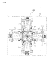
- Figs.16 and 17 show the fifth embodiment of the light source of illumination of the present invention.
- Fig.16 is a plane view of a light source of illumination for a light guide according to this preferred embodiment of the present invention.
- Fig.17 is a plane view showing a main part of the light source unit.
- a light source of illumination 200 has a box-like casing 210, and a power supply circuit 220 is provided inside the casing 210 and a cooling fan 230 is provided in each light source unit 240.
- two pairs of light source units 240 are arranged so that these surround a polyhedral reflection mirror 250 and the light beams from the light source units 240 are reflected by respective faces of the polyhedral reflection mirror 250. Further, the optical connector 260 is located at the position on which the light beams reflected or turned by the polyhedral reflection mirror 250 are substantially focused.
- a concave mirror 241 is located at the position opposite to a first light-emitting diode group 242 supported by a first board 243.
- the first board 243 has a circular light-delivering hole 244 at the center, and the first light-emitting diode group 242 is arranged annularly surrounding the light-delivering hole 244.
- the concave mirror 241 is equal to the concave mirror 150(b) of the fourth embodiment and has a configuration that a circle is cut along parallel straight lines each connecting points opposite to each other on the circumference.
- the first light-emitting diode group 242 is preferably located in at least two steps in the vertical direction on the surface of the first board 243 .
- they are arranged stepwise in three steps. In this case, it is preferred to arrange them so that respective steps partially overlap as shown in Fig.17, in order to increase the number of the light-emitting diodes on the same area, by which the density of arrangement of the light-emitting diodes can be increased and the quantity of light can be increased.
- a second board 249 supporting a second light-emitting diode group 248, is supported and connected to the back face side of the concave mirror 241 so that the second light-emitting part of the second light-emitting diode group 248 face the first light-emitting diode group 242.
- the front end portion of the second light-emitting diode group 248 is inserted into the central hole 245 of the concave mirror 241, and the light beams emitted from the second light-emitting diode group 248 are directly irradiated toward the polyhedral reflection mirror 250 through the hole 245, as indicated by the imaginary line in Fig.17.
- the light beams collected from the respective light source units 240 are then reflected and turned by the polyhedral reflection mirror 250 and collected on one point.
- the polyhedral reflection mirror 250 has several reflection faces corresponding to the number of the light source units 240, and in the example of Fig.16, has a shape of a triangular prism.
- the polyhedral reflection mirror 250 ones obtained by polishing a metal such as aluminum or brass or ones obtained by molding glass or a synthetic resin and depositing thereon a metal such as aluminum, and the like are suitably used.
- the optical connector 260 has an insertion hole 261 for an optical fiber cable (not shown).
- the light beams emitted from the first light-emitting diode group 242 are reflected by the concave mirror 241, and further reflected by the corresponding reflection faces of the polyhedral reflection mirror 250 and collected to a light-introducing portion of the optical connector 260.
- the light beams collected from the respective light source units 240 are further reflected and turned by the polyhedral reflection mirror 250 and collected on one point, whereby a quantity of light comparable to halogen lamps can easily be obtained.
- the concave mirror of each one can be kept small, whereby the degree of freedom of the configuration of the casing is increased and the installation space can be utilized as highly as possible. Further, since the concave mirror can always be manufactured with the same size and the whole quantity of light can be determined by the number of the light source units, the production parts can be commonized and the production costs can be reduced.
- Fig.18 shows the sixth embodiment of the light source of illumination for the light guide according to the present invention.
- the substantially same parts as in the fifth embodiment are indicated by the same reference numerals, and explanation thereof is omitted.
- a light source of illumination for a light guide 200' in a light source of illumination for a light guide 200', four pairs of light source units 240 are arranged in the casing 210 surrounding the polyhedral reflection mirror 251, and the light beams from the respective light source 240 are irradiated on the corresponding reflection faces of the polyhedral reflection mirror 251.
- the difference from the previous embodiment resides in a point that four pairs of the light source units 240 are used and the configuration of the reflection mirror 251 is a quadrangular pyramid shape.
- the quantity of light is increased to about 2 times as compared with the fifth embodiment.
- the quantity of light can be freely increased by the combination of the reflection mirror and the number of the light source units as mentioned above. Further, by combining plural light source units, even if the number of the light-emitting diodes increases, the concave mirror for each one can be kept small, whereby the degree of freedom of the casing can be increased and the installation space can be utilized as highly as possible. Further, since the concave mirror can always be manufactured with the same size and the whole quantity of light can be determined by the number of the light source units, the production step is simple and the light source units can be commonized, leading to reduction of production costs.
- Figs.19 and 20 show another embodiment of the polyhedral reflection mirror of the present invention.
- This embodiment is different from the previous one in that the surfaces of the polyhedral reflection mirrors 252, 253 have concave curved faces 252a, 253a, respectively.
- the light source of the light-emitting diode have a spread ranging from about 8 degree to about 25 degree depending upon the color of the light source. Accordingly, by forming the respective faces of the polyhedral reflection mirror into a concave curved face, it is possible to not only simply reflect and turn the light flux from the respective light source units 240, but also collect the reflected light beams again, whereby the light-collecting efficiency of the light beams entered into the optical fibers can be increased.
- the present invention at least in its preferred forms, it is possible to produce an apparatus having a long lifetime, for which no replacement of lamps is required, at a relatively low cost, and to obtain sufficient quantity of light by a small-sized apparatus. Further, the shape of the casing can be changed flexibly depending upon the installation space. Moreover, it is possible to provide a light source of illumination for a light guide, which is small in size and provide a quantity of light sufficient for inspection.
Landscapes
- Physics & Mathematics (AREA)
- General Physics & Mathematics (AREA)
- Optics & Photonics (AREA)
- Investigating Materials By The Use Of Optical Means Adapted For Particular Applications (AREA)
- Led Device Packages (AREA)
- Optical Couplings Of Light Guides (AREA)
Applications Claiming Priority (4)
| Application Number | Priority Date | Filing Date | Title |
|---|---|---|---|
| JP2000363622 | 2000-11-29 | ||
| JP2000363593A JP2002170416A (ja) | 2000-11-29 | 2000-11-29 | ライトガイド用照明光源 |
| JP2000363593 | 2000-11-29 | ||
| JP2000363622A JP2002170404A (ja) | 2000-11-29 | 2000-11-29 | ライトガイド用照明光源 |
Publications (1)
| Publication Number | Publication Date |
|---|---|
| EP1211457A1 true EP1211457A1 (de) | 2002-06-05 |
Family
ID=26604857
Family Applications (1)
| Application Number | Title | Priority Date | Filing Date |
|---|---|---|---|
| EP01309995A Withdrawn EP1211457A1 (de) | 2000-11-29 | 2001-11-29 | Beleuchtungslichtquelle für Lichtleiter |
Country Status (4)
| Country | Link |
|---|---|
| US (1) | US20020064043A1 (de) |
| EP (1) | EP1211457A1 (de) |
| KR (1) | KR20020042417A (de) |
| CN (1) | CN1356492A (de) |
Cited By (3)
| Publication number | Priority date | Publication date | Assignee | Title |
|---|---|---|---|---|
| WO2004031850A1 (ja) * | 2002-10-01 | 2004-04-15 | Olympus Corporation | 投影表示装置 |
| WO2004057384A1 (en) * | 2002-12-20 | 2004-07-08 | Koninklijke Philips Electronics N.V. | Apparatus and method for illuminating a rod |
| US7309134B2 (en) | 2003-04-21 | 2007-12-18 | Infocus Corporation | System and method for displaying projector system identification information |
Families Citing this family (18)
| Publication number | Priority date | Publication date | Assignee | Title |
|---|---|---|---|---|
| KR100426786B1 (ko) * | 2002-05-27 | 2004-04-28 | 정천수 | 광섬유용 풀컬러 광원장치 |
| US6880954B2 (en) | 2002-11-08 | 2005-04-19 | Smd Software, Inc. | High intensity photocuring system |
| US6995355B2 (en) * | 2003-06-23 | 2006-02-07 | Advanced Optical Technologies, Llc | Optical integrating chamber lighting using multiple color sources |
| US20070138978A1 (en) * | 2003-06-23 | 2007-06-21 | Advanced Optical Technologies, Llc | Conversion of solid state source output to virtual source |
| US20070051883A1 (en) * | 2003-06-23 | 2007-03-08 | Advanced Optical Technologies, Llc | Lighting using solid state light sources |
| US20070171649A1 (en) * | 2003-06-23 | 2007-07-26 | Advanced Optical Technologies, Llc | Signage using a diffusion chamber |
| US7145125B2 (en) | 2003-06-23 | 2006-12-05 | Advanced Optical Technologies, Llc | Integrating chamber cone light using LED sources |
| US7521667B2 (en) * | 2003-06-23 | 2009-04-21 | Advanced Optical Technologies, Llc | Intelligent solid state lighting |
| US20070235639A1 (en) * | 2003-06-23 | 2007-10-11 | Advanced Optical Technologies, Llc | Integrating chamber LED lighting with modulation to set color and/or intensity of output |
| CN1333469C (zh) * | 2003-10-31 | 2007-08-22 | 百容电子股份有限公司 | 发光二极管高效能散热的支持装置 |
| US7144131B2 (en) * | 2004-09-29 | 2006-12-05 | Advanced Optical Technologies, Llc | Optical system using LED coupled with phosphor-doped reflective materials |
| WO2007083552A1 (ja) * | 2006-01-17 | 2007-07-26 | Mitsubishi Heavy Industries, Ltd. | 光源用ランプおよびプロジェクター |
| US7802910B2 (en) | 2008-01-29 | 2010-09-28 | Dymax Corporation | Light guide exposure device |
| CN101655217B (zh) * | 2008-08-21 | 2011-11-09 | 鸿富锦精密工业(深圳)有限公司 | 灯壳 |
| USD629947S1 (en) * | 2009-02-13 | 2010-12-28 | PerkinElmer LED Solutions, Inc. | LED-based fiber illuminator |
| TWI422774B (zh) * | 2010-11-26 | 2014-01-11 | Wintek China Technology Ltd | 發光二極體光源箱及應用其之照明組件 |
| SE537987C2 (sv) * | 2014-04-07 | 2016-01-12 | Cgrain Ab | Avbildningssystem för granulärt material med homogen bakgrund |
| FR3034497B1 (fr) * | 2015-04-03 | 2020-02-07 | Xyzed | Source de lumiere monochromatique a diodes |
Citations (2)
| Publication number | Priority date | Publication date | Assignee | Title |
|---|---|---|---|---|
| JPH11219608A (ja) * | 1998-01-30 | 1999-08-10 | Tb Optical Kk | ライトガイド用照明光源及び照明装置 |
| WO2000036336A1 (en) * | 1998-12-17 | 2000-06-22 | Koninklijke Philips Electronics N.V. | Light engine |
-
2001
- 2001-11-05 US US09/991,825 patent/US20020064043A1/en not_active Abandoned
- 2001-11-10 KR KR1020010069926A patent/KR20020042417A/ko not_active Withdrawn
- 2001-11-29 EP EP01309995A patent/EP1211457A1/de not_active Withdrawn
- 2001-11-29 CN CN01142935A patent/CN1356492A/zh active Pending
Patent Citations (2)
| Publication number | Priority date | Publication date | Assignee | Title |
|---|---|---|---|---|
| JPH11219608A (ja) * | 1998-01-30 | 1999-08-10 | Tb Optical Kk | ライトガイド用照明光源及び照明装置 |
| WO2000036336A1 (en) * | 1998-12-17 | 2000-06-22 | Koninklijke Philips Electronics N.V. | Light engine |
Non-Patent Citations (1)
| Title |
|---|
| PATENT ABSTRACTS OF JAPAN vol. 1999, no. 13 30 November 1999 (1999-11-30) * |
Cited By (5)
| Publication number | Priority date | Publication date | Assignee | Title |
|---|---|---|---|---|
| WO2004031850A1 (ja) * | 2002-10-01 | 2004-04-15 | Olympus Corporation | 投影表示装置 |
| US7029129B2 (en) | 2002-10-01 | 2006-04-18 | Olympus Corporation | Projection display apparatus |
| US7118221B2 (en) | 2002-10-01 | 2006-10-10 | Olympus Corporation | Projection display apparatus |
| WO2004057384A1 (en) * | 2002-12-20 | 2004-07-08 | Koninklijke Philips Electronics N.V. | Apparatus and method for illuminating a rod |
| US7309134B2 (en) | 2003-04-21 | 2007-12-18 | Infocus Corporation | System and method for displaying projector system identification information |
Also Published As
| Publication number | Publication date |
|---|---|
| CN1356492A (zh) | 2002-07-03 |
| US20020064043A1 (en) | 2002-05-30 |
| KR20020042417A (ko) | 2002-06-05 |
Similar Documents
| Publication | Publication Date | Title |
|---|---|---|
| EP1211457A1 (de) | Beleuchtungslichtquelle für Lichtleiter | |
| US6161941A (en) | Light array system and method for illumination of objects imaged by imaging systems | |
| EP0873551B1 (de) | Beleuchtungssystem zum optischen lesen von merkmalen auf einem substrat | |
| US9192290B2 (en) | Illumination apparatus for an image sensing means at the distal end of an endoscope | |
| US6964508B2 (en) | Fiber optic bundle lighting units providing focused illumination | |
| US6595674B1 (en) | Lighting device for surface inspection | |
| CN1287625A (zh) | 显微镜照明装置 | |
| JP3423304B1 (ja) | 光照射装置及び光照射ユニット | |
| JP2013532838A (ja) | 照明システム | |
| JP2010127897A (ja) | リング型照明装置 | |
| KR20030015207A (ko) | 결상 시스템 | |
| US5758942A (en) | Mechanical vision system using selective wavelength and brightness illumination | |
| JP2002170404A (ja) | ライトガイド用照明光源 | |
| JPH11219608A (ja) | ライトガイド用照明光源及び照明装置 | |
| JP2004191214A (ja) | ライン照明装置及びライン照明装置を用いた検査装置 | |
| JP2002170416A (ja) | ライトガイド用照明光源 | |
| JP2001084819A (ja) | ライトガイド用照明光源 | |
| JPH1166937A (ja) | 照明装置 | |
| JP3160593B2 (ja) | 照明装置 | |
| US20090153860A1 (en) | Optical comparator using light- emitting diode light sources | |
| JP7807619B2 (ja) | 画像処理検査用同軸落射照明装置 | |
| US6292580B1 (en) | Efficient illumination system for wire bonders | |
| KR100855539B1 (ko) | 고조도 led 조명장치 | |
| TW514710B (en) | Light source of illumination for light guide | |
| JP2001356247A (ja) | 照明装置 |
Legal Events
| Date | Code | Title | Description |
|---|---|---|---|
| PUAI | Public reference made under article 153(3) epc to a published international application that has entered the european phase |
Free format text: ORIGINAL CODE: 0009012 |
|
| AK | Designated contracting states |
Kind code of ref document: A1 Designated state(s): AT BE CH CY DE DK ES FI FR GB GR IE IT LI LU MC NL PT SE TR |
|
| AX | Request for extension of the european patent |
Free format text: AL;LT;LV;MK;RO;SI |
|
| AKX | Designation fees paid | ||
| REG | Reference to a national code |
Ref country code: DE Ref legal event code: 8566 |
|
| STAA | Information on the status of an ep patent application or granted ep patent |
Free format text: STATUS: THE APPLICATION IS DEEMED TO BE WITHDRAWN |
|
| 18D | Application deemed to be withdrawn |
Effective date: 20021206 |