EP1211471B1 - Four électrique pour la production d'oxydes métalliques - Google Patents
Four électrique pour la production d'oxydes métalliques Download PDFInfo
- Publication number
- EP1211471B1 EP1211471B1 EP01500124A EP01500124A EP1211471B1 EP 1211471 B1 EP1211471 B1 EP 1211471B1 EP 01500124 A EP01500124 A EP 01500124A EP 01500124 A EP01500124 A EP 01500124A EP 1211471 B1 EP1211471 B1 EP 1211471B1
- Authority
- EP
- European Patent Office
- Prior art keywords
- furnace
- screw
- production
- metal oxides
- electric furnace
- Prior art date
- Legal status (The legal status is an assumption and is not a legal conclusion. Google has not performed a legal analysis and makes no representation as to the accuracy of the status listed.)
- Expired - Lifetime
Links
- 238000004519 manufacturing process Methods 0.000 title claims description 15
- 229910044991 metal oxide Inorganic materials 0.000 title claims description 11
- 150000004706 metal oxides Chemical class 0.000 title claims description 11
- 239000002994 raw material Substances 0.000 claims abstract description 20
- 238000010438 heat treatment Methods 0.000 claims abstract description 16
- 238000009527 percussion Methods 0.000 claims abstract description 6
- 238000005056 compaction Methods 0.000 claims abstract description 4
- 230000005855 radiation Effects 0.000 claims abstract description 3
- 239000000919 ceramic Substances 0.000 claims description 3
- 238000009413 insulation Methods 0.000 claims description 3
- 230000005484 gravity Effects 0.000 claims description 2
- 239000000047 product Substances 0.000 description 8
- 239000011449 brick Substances 0.000 description 4
- 239000000126 substance Substances 0.000 description 4
- 238000010276 construction Methods 0.000 description 3
- 239000012467 final product Substances 0.000 description 3
- 230000008878 coupling Effects 0.000 description 2
- 238000010168 coupling process Methods 0.000 description 2
- 238000005859 coupling reaction Methods 0.000 description 2
- 239000000835 fiber Substances 0.000 description 2
- 239000000463 material Substances 0.000 description 2
- 238000000034 method Methods 0.000 description 2
- 230000008569 process Effects 0.000 description 2
- 230000009467 reduction Effects 0.000 description 2
- 239000000523 sample Substances 0.000 description 2
- 229910000831 Steel Inorganic materials 0.000 description 1
- 230000009471 action Effects 0.000 description 1
- 230000005540 biological transmission Effects 0.000 description 1
- 238000006073 displacement reaction Methods 0.000 description 1
- 238000005265 energy consumption Methods 0.000 description 1
- 238000000605 extraction Methods 0.000 description 1
- 230000006698 induction Effects 0.000 description 1
- 238000009434 installation Methods 0.000 description 1
- 229910000464 lead oxide Inorganic materials 0.000 description 1
- HTUMBQDCCIXGCV-UHFFFAOYSA-N lead oxide Chemical compound [O-2].[Pb+2] HTUMBQDCCIXGCV-UHFFFAOYSA-N 0.000 description 1
- YEXPOXQUZXUXJW-UHFFFAOYSA-N lead(II) oxide Inorganic materials [Pb]=O YEXPOXQUZXUXJW-UHFFFAOYSA-N 0.000 description 1
- 238000012423 maintenance Methods 0.000 description 1
- 239000011819 refractory material Substances 0.000 description 1
- 229910001220 stainless steel Inorganic materials 0.000 description 1
- 239000010935 stainless steel Substances 0.000 description 1
- 239000010959 steel Substances 0.000 description 1
Images



Classifications
-
- F—MECHANICAL ENGINEERING; LIGHTING; HEATING; WEAPONS; BLASTING
- F27—FURNACES; KILNS; OVENS; RETORTS
- F27D—DETAILS OR ACCESSORIES OF FURNACES, KILNS, OVENS OR RETORTS, IN SO FAR AS THEY ARE OF KINDS OCCURRING IN MORE THAN ONE KIND OF FURNACE
- F27D3/00—Charging; Discharging; Manipulation of charge
- F27D3/08—Screw feeders; Screw dischargers
-
- F—MECHANICAL ENGINEERING; LIGHTING; HEATING; WEAPONS; BLASTING
- F27—FURNACES; KILNS; OVENS; RETORTS
- F27B—FURNACES, KILNS, OVENS OR RETORTS IN GENERAL; OPEN SINTERING OR LIKE APPARATUS
- F27B9/00—Furnaces through which the charge is moved mechanically, e.g. of tunnel type; Similar furnaces in which the charge moves by gravity
- F27B9/06—Furnaces through which the charge is moved mechanically, e.g. of tunnel type; Similar furnaces in which the charge moves by gravity heated without contact between combustion gases and charge; electrically heated
- F27B9/062—Furnaces through which the charge is moved mechanically, e.g. of tunnel type; Similar furnaces in which the charge moves by gravity heated without contact between combustion gases and charge; electrically heated electrically heated
- F27B9/063—Resistor heating, e.g. with resistors also emitting IR rays
-
- F—MECHANICAL ENGINEERING; LIGHTING; HEATING; WEAPONS; BLASTING
- F27—FURNACES; KILNS; OVENS; RETORTS
- F27B—FURNACES, KILNS, OVENS OR RETORTS IN GENERAL; OPEN SINTERING OR LIKE APPARATUS
- F27B9/00—Furnaces through which the charge is moved mechanically, e.g. of tunnel type; Similar furnaces in which the charge moves by gravity
- F27B9/30—Details, accessories or equipment specially adapted for furnaces of these types
- F27B9/32—Casings
-
- F—MECHANICAL ENGINEERING; LIGHTING; HEATING; WEAPONS; BLASTING
- F27—FURNACES; KILNS; OVENS; RETORTS
- F27B—FURNACES, KILNS, OVENS OR RETORTS IN GENERAL; OPEN SINTERING OR LIKE APPARATUS
- F27B9/00—Furnaces through which the charge is moved mechanically, e.g. of tunnel type; Similar furnaces in which the charge moves by gravity
- F27B9/30—Details, accessories or equipment specially adapted for furnaces of these types
- F27B9/32—Casings
- F27B9/34—Arrangements of linings
-
- F—MECHANICAL ENGINEERING; LIGHTING; HEATING; WEAPONS; BLASTING
- F27—FURNACES; KILNS; OVENS; RETORTS
- F27D—DETAILS OR ACCESSORIES OF FURNACES, KILNS, OVENS OR RETORTS, IN SO FAR AS THEY ARE OF KINDS OCCURRING IN MORE THAN ONE KIND OF FURNACE
- F27D11/00—Arrangement of elements for electric heating in or on furnaces
- F27D11/02—Ohmic resistance heating
-
- F—MECHANICAL ENGINEERING; LIGHTING; HEATING; WEAPONS; BLASTING
- F27—FURNACES; KILNS; OVENS; RETORTS
- F27B—FURNACES, KILNS, OVENS OR RETORTS IN GENERAL; OPEN SINTERING OR LIKE APPARATUS
- F27B9/00—Furnaces through which the charge is moved mechanically, e.g. of tunnel type; Similar furnaces in which the charge moves by gravity
- F27B9/14—Furnaces through which the charge is moved mechanically, e.g. of tunnel type; Similar furnaces in which the charge moves by gravity characterised by the path of the charge during treatment; characterised by the means by which the charge is moved during treatment
- F27B9/20—Furnaces through which the charge is moved mechanically, e.g. of tunnel type; Similar furnaces in which the charge moves by gravity characterised by the path of the charge during treatment; characterised by the means by which the charge is moved during treatment the charge moving in a substantially straight path
- F27B9/24—Furnaces through which the charge is moved mechanically, e.g. of tunnel type; Similar furnaces in which the charge moves by gravity characterised by the path of the charge during treatment; characterised by the means by which the charge is moved during treatment the charge moving in a substantially straight path being carried by a conveyor
- F27B2009/2484—Furnaces through which the charge is moved mechanically, e.g. of tunnel type; Similar furnaces in which the charge moves by gravity characterised by the path of the charge during treatment; characterised by the means by which the charge is moved during treatment the charge moving in a substantially straight path being carried by a conveyor the conveyor being a helical device
-
- F—MECHANICAL ENGINEERING; LIGHTING; HEATING; WEAPONS; BLASTING
- F27—FURNACES; KILNS; OVENS; RETORTS
- F27B—FURNACES, KILNS, OVENS OR RETORTS IN GENERAL; OPEN SINTERING OR LIKE APPARATUS
- F27B9/00—Furnaces through which the charge is moved mechanically, e.g. of tunnel type; Similar furnaces in which the charge moves by gravity
- F27B9/30—Details, accessories or equipment specially adapted for furnaces of these types
- F27B9/38—Arrangements of devices for charging
- F27B2009/386—Lateral intake or outtake
-
- F—MECHANICAL ENGINEERING; LIGHTING; HEATING; WEAPONS; BLASTING
- F27—FURNACES; KILNS; OVENS; RETORTS
- F27B—FURNACES, KILNS, OVENS OR RETORTS IN GENERAL; OPEN SINTERING OR LIKE APPARATUS
- F27B9/00—Furnaces through which the charge is moved mechanically, e.g. of tunnel type; Similar furnaces in which the charge moves by gravity
- F27B9/14—Furnaces through which the charge is moved mechanically, e.g. of tunnel type; Similar furnaces in which the charge moves by gravity characterised by the path of the charge during treatment; characterised by the means by which the charge is moved during treatment
- F27B9/20—Furnaces through which the charge is moved mechanically, e.g. of tunnel type; Similar furnaces in which the charge moves by gravity characterised by the path of the charge during treatment; characterised by the means by which the charge is moved during treatment the charge moving in a substantially straight path
- F27B9/24—Furnaces through which the charge is moved mechanically, e.g. of tunnel type; Similar furnaces in which the charge moves by gravity characterised by the path of the charge during treatment; characterised by the means by which the charge is moved during treatment the charge moving in a substantially straight path being carried by a conveyor
- F27B9/243—Endless-strand conveyor
-
- F—MECHANICAL ENGINEERING; LIGHTING; HEATING; WEAPONS; BLASTING
- F27—FURNACES; KILNS; OVENS; RETORTS
- F27D—DETAILS OR ACCESSORIES OF FURNACES, KILNS, OVENS OR RETORTS, IN SO FAR AS THEY ARE OF KINDS OCCURRING IN MORE THAN ONE KIND OF FURNACE
- F27D19/00—Arrangements of controlling devices
- F27D2019/0006—Monitoring the characteristics (composition, quantities, temperature, pressure) of at least one of the gases of the kiln atmosphere and using it as a controlling value
- F27D2019/0018—Monitoring the temperature of the atmosphere of the kiln
-
- F—MECHANICAL ENGINEERING; LIGHTING; HEATING; WEAPONS; BLASTING
- F27—FURNACES; KILNS; OVENS; RETORTS
- F27D—DETAILS OR ACCESSORIES OF FURNACES, KILNS, OVENS OR RETORTS, IN SO FAR AS THEY ARE OF KINDS OCCURRING IN MORE THAN ONE KIND OF FURNACE
- F27D19/00—Arrangements of controlling devices
- F27D2019/0028—Regulation
- F27D2019/0034—Regulation through control of a heating quantity such as fuel, oxidant or intensity of current
- F27D2019/0037—Quantity of electric current
-
- F—MECHANICAL ENGINEERING; LIGHTING; HEATING; WEAPONS; BLASTING
- F27—FURNACES; KILNS; OVENS; RETORTS
- F27M—INDEXING SCHEME RELATING TO ASPECTS OF THE CHARGES OR FURNACES, KILNS, OVENS OR RETORTS
- F27M2001/00—Composition, conformation or state of the charge
- F27M2001/01—Charges containing mainly non-ferrous metals
- F27M2001/017—Lead
Definitions
- the present invention relates to an electric furnace for the production of metal oxides and, in particular, to the production of lead oxides with high standards of quality of the product and of the process, affording considerable advantages over the prior art.
- EP-A-0 406 954 discloses an induction furnace for the production of litharge.
- the main objects of the present invention are to achieve a high quality of the final product and great flexibility with regard to the quality of the raw material, combined with easy management of the furnace, with a reliable and precise control system, and with a reduction in problems in the working environment and in the environment outside the plant. Moreover, according to the present invention, it is possible to achieve considerable advantages over currently known furnaces, such as:
- the present invention provides for a tubular furnace with a tubular treatment chamber made of stainless refractory steel (AISI-310) and provided with a plurality of heating zones with individual control probes, in particular, three heating zones, each of which comprises six resistors connected so as to achieve a balance in electrical consumption between phases, each heating zone having its optimal adjustment point in dependence on the quality of the raw material, on its physical and chemical characteristics, and on the physical and chemical characteristics of the finished product to be produced.
- AISI-310 stainless refractory steel
- the electrical control panel comprises controllers of consumption per phase and of voltage between phases, and can warn of any electrical problem with the resistors.
- the heating control system permits adjustment of the electrical consumption of the furnace at any moment in dependence on the state of the furnace, as well as the use of full power during start-up and, during the normal process, consumption controlled by the temperatures of the chamber.
- the construction of the furnace enables great functional flexibility to be achieved therein in order to adapt to the quality of the raw material used, for which purpose energy consumption is adjusted according to the quality of the raw material.
- the raw material introduced into the tubular chamber is urged by an agitator shaft towards the end of the furnace body at which the finished product is discharged by a rotary valve.
- the agitator shaft rotates by virtue of the driving action of a geared motor unit controlled by a frequency meter from the control panel of the furnace.
- the agitator shaft is of mixed construction, with the use of AISI-310 stainless steel in the portion which is in contact with the product and AISI-304 for the rest. It is constituted by a central tubular element with a square cross-section, constituted by welded plates and a set of vanes welded to the central tube on its respective faces and arranged in a manner such as together to constitute a helical screw.
- One of the characteristics of the agitator shaft of the furnace of the present invention is that it has, in its outer portions, percussion devices or “hammers” with balls inside them which, by virtue of the rotation of the agitator shaft, cause impacts and vibration inside the shaft, preventing the product from adhering to the shaft.
- the quality of the final product is adjusted by control of the time spent by the product inside the furnace and also by the output or final production flow, for which purpose the present invention provides for a frequency variator which controls the rate of rotation of the agitator shaft and also the rate of rotation of the helical screw which feeds raw material to the furnace.
- a frequency variator which controls the rate of rotation of the agitator shaft and also the rate of rotation of the helical screw which feeds raw material to the furnace.
- two separate speed variators one for the agitator shaft and the other for the worm screw for feeding the raw material to the furnace itself.
- the furnace as a whole is thermally insulated by refractory bricks with a temperature classification of up to 1,260°C, the bricks additionally providing the necessary support for the electrical resistors.
- the insulation is completed by high-density ceramic fibre (128 kg/m 3 ) with a temperature classification of up to 1,260°C.
- movable elements are provided which allow the tube to lengthen freely.
- a free extension system is provided, which takes up the expansions of the tubular chamber and of the displacement screw resulting from the temperature difference produced inside the heating chamber.
- the furnace is controlled by a centralized panel which comprises the elements necessary for the control of temperature in the chamber of the furnace and alarm elements for providing warnings when the values of the control parameters depart from the range of values provided for during the production process.
- Figure 1 is a partially-sectioned, side elevational view of the furnace of the present invention.
- Figure 2 is an elevational view taken from one end of the furnace.
- Figure 3 shows a detail in a section taken in the section plane indicated.
- Figure 4 shows, in cross-section, a detail of the mounting of the heating resistors.
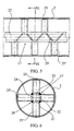
- FIGS 5 and 6 show respective details of the main screw of the furnace.
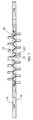
- Figure 7 is a schematic side elevational view of the entire main screw.
- Figure 8 shows a detail of one end of the main screw.
- FIGS. 9, 10 and 11 show respective details of the furnace in cross-sections taken in the section planes indicated.
- the furnace of the present invention comprises a main body 1 of tubular structure, of which the central element is constituted by the tubular chamber 2 of the furnace mounted in the furnace body, which is insulated by means of refractory bricks 3 and insulation layers based on high-density ceramic fibre, indicated in the upper portion by the numeral 4.
- the furnace is heated by radiation, by panels of electrical resistors incorporated in the body of the furnace, as can be seen in the detail of Figure 4 in which the furnace body 1 is mounted on a support frame composed principally of a variable number of upright posts 5 and 6 for fixing the furnace to the floor; in the interior, it is possible to see the mounting of the lateral panels of heating resistors 7 and 8 which are incorporated in the insulating refractory material composed of the refractory bricks 3 having a temperature classification of up to 1,260°C.
- a plurality of heating zones, preferably three zones, are disposed along the furnace, each zone having six resistors distributed longitudinally.
- Each of the three heating zones will be provided with two K-type temperature probes for the control of the heating resistors.
- Each of the heating zones can utilize its optimal adjustment point in dependence on the quality of the raw material, on the physical and chemical characteristics thereof, and on the physical and chemical characteristics of the final product to be produced.
- the input of raw material will take place through a feed pipe 9, shown in broken outline, provided with an helical screw for forcing the material to enter the chamber 2 through the duct 10.
- a feed pipe 9 shown in broken outline, provided with an helical screw for forcing the material to enter the chamber 2 through the duct 10.
- the output of the product after it has been treated as it travels along the tubular chamber 2, will take place at the opposite end through a gravity outlet 12, into a rotary collector 13 driven by an independent geared motor unit 14.
- At the actual outlet of the furnace chamber there will be an air-inlet 15 and optional air extraction 16, both being controlled by corresponding valves.
- the raw material is moved along the main chamber 2 of the furnace by an internal screw of special construction, indicated 17 in Figures 1 and 5 to 11.
- the screw is rotated by a geared motor unit 18 and a transmission system 19 with belts, chains, or the like.
- the screw 17 is constituted by a square, tubular central element, as can be seen in Figure 6, in which it is possible to see the screw 17, which is constituted by a square central tubular element 20 with faces 21, 22, 23 and 24 on which sets of aligned vanes 25, 25', -25"... are fixed, the vanes being arranged at suitable inclinations so as together to form a helical screw for moving the raw material along the tubular chamber of the furnace.
- Respective percussion devices or “hammers”, indicated 26 and 27 in Figure 1, are incorporated in the ends of the agitator shaft 17.
- Each of these elements is constituted by a central tubular body, Figure 2, and respective short end extensions 27 and 28 of predetermined inclination, there being disposed inside the elements, some free masses such as spheres 29 and 30, which can be moved along the tubular elements upon rotation of the screw, giving rise to impacts which prevent adhesion or compaction of the material on the screw.
- the central tubular element 20 forming the drive screw has ends to which the drive and percussion members can be coupled by keying as can be seen in Figure 8 and the following drawings.
- a tubular extension 31 is coupled to the square tubular element 20 by means of an internal coupling sleeve 32 which is coupled with the two tubular elements enabling the end 21 to have openings 33 of suitable shape and arrangement for the coupling of the drive members of the furnace.
Landscapes
- Engineering & Computer Science (AREA)
- Mechanical Engineering (AREA)
- General Engineering & Computer Science (AREA)
- Chemical & Material Sciences (AREA)
- Combustion & Propulsion (AREA)
- Oxygen, Ozone, And Oxides In General (AREA)
- Furnace Details (AREA)
Claims (9)
- Four électrique pour la production d'oxydes métalliques,comprenant une chambre interne tubulaire (2) pour le traitement de la matière première, montée à l'intérieur du corps enveloppant du four qui est isolé de l'extérieur et muni de systèmes de résistances internes pour chauffer la chambre du four par rayonnement, comprenant des moyens pour alimenter la matière première sur une extrémité et des moyens pour commander la sortie du produit achevé à l'autre extrémité de la chambre de traitement du four, à l'intérieur duquel une vis hélicoïdale (17) actionnée en rotation depuis l'extérieur, est montée de façon rotative, des dispositifs de percussion respectifs (26,27) étant incorporés dans les extrémités de la vis pour empêcher le compactage de la masse sur la vis.
- Four électrique pour la production d'oxydes métalliques selon la revendication 1, dans lequel vis pour déplacer la matière première est composée d'un corps central sur la surface extérieur duquel sont fixés des séries de pales alignées (25,25',25") disposées selon une inclinaison de façon à former ensemble une vis hélicoïdale pour déplacer la masse à traiter.
- Four électrique pour la production d'oxydes métalliques selon la revendication 2, dans lequel le corps central de la vis est conçu avec une forme carrée, prismatique par des plaques, soudées ensemble, formant ses faces.
- Four électrique pour la production d'oxydes métalliques selon la revendication 1, caractérisé en ce que les résistances de chauffage sont disposées en séries respectives en alignement sur les parois latérales du corps enveloppant du four, sur les côtés opposés de la chambre de traitement tubulaire, et divisée en une pluralité de sections longitudinales commandées indépendamment, permettant des points d'ajustement de température indépendante pour adapter le four aux différentes caractéristiques de la matière première et du produit à réaliser.
- Four électrique pour la production d'oxydes métalliques selon la revendication 1, dans lequel le corps enveloppant du four comprend une maçonnerie réfractaire isolante qui loge également les résistances de chauffage, l'isolation étant réalisée sur le sommet par des fibres céramiques haute densité.
- Four électrique pour la production d'oxydes métalliques selon la revendication 1, dans lequel chacun des dispositifs de percussion montés sur les extrémités de l'arbre de la vis centrale pour déplacer la masse à traiter est formé par un élément tubulaire transversal en agencement symétrique par rapport à l'axe de la vis et doté d'extrémités fermées plus courtes (28) d'inclinaison prédéterminée, à l'intérieur desquelles se trouvent des masses librement mobiles (29) qui peuvent produire des impacts pendant la rotation de la vis, empêchant le compactage de la masse à traiter.
- Four électrique pour la production d'oxydes métalliques selon la revendication 1, dans lequel sur l'extrémité d'entrée du four se trouve un alimentateur à vis sans fin pour l'entrée de matière première, également muni d'une entrée d'air et, à l'extrémité de la sortie de la matière première, il est prévu une sortie par gravité et un collecteur rotatif, et une entrée et une sortie d'air respectives, commandées par des soupapes respectives.
- Four électrique pour la production d'oxydes métalliques selon la revendication 1, dans lequel la vis d'entraínement de la chambre de traitement du four est commandée en rotation à l'aide d'un variateur de fréquence qui commande simultanément la vitesse de rotation de la vis sans fin de la chambre de traitement et celle de l'élément d'alimentation tubulaire de matière première.
- Four électrique pour la production d'oxydes métalliques selon la revendication 1, ayant un système d'extension libre qui absorbe les expansions de la chambre tubulaire et de la vis de mouvement résultant de la différence des températures produites à l'intérieur de la chambre de chauffage.
Applications Claiming Priority (2)
| Application Number | Priority Date | Filing Date | Title |
|---|---|---|---|
| ES200002840A ES2184583B1 (es) | 2000-11-28 | 2000-11-28 | Horno electrico para la produccion de oxidos metalicos. |
| ES200002840 | 2000-11-28 |
Publications (3)
| Publication Number | Publication Date |
|---|---|
| EP1211471A2 EP1211471A2 (fr) | 2002-06-05 |
| EP1211471A3 EP1211471A3 (fr) | 2003-11-26 |
| EP1211471B1 true EP1211471B1 (fr) | 2004-10-06 |
Family
ID=8495785
Family Applications (1)
| Application Number | Title | Priority Date | Filing Date |
|---|---|---|---|
| EP01500124A Expired - Lifetime EP1211471B1 (fr) | 2000-11-28 | 2001-05-18 | Four électrique pour la production d'oxydes métalliques |
Country Status (7)
| Country | Link |
|---|---|
| US (1) | US6700918B2 (fr) |
| EP (1) | EP1211471B1 (fr) |
| AT (1) | ATE278921T1 (fr) |
| BR (1) | BR0105522B1 (fr) |
| DE (1) | DE60106179D1 (fr) |
| ES (2) | ES2184583B1 (fr) |
| MX (1) | MXPA01011617A (fr) |
Families Citing this family (3)
| Publication number | Priority date | Publication date | Assignee | Title |
|---|---|---|---|---|
| FR2924300B1 (fr) * | 2007-11-23 | 2009-12-04 | E T I A Evaluation Technologiq | Dispositif de traitement thermique de solides divises. |
| FR3101699B1 (fr) * | 2019-10-08 | 2021-09-10 | E T I A Evaluation Tech Ingenierie Et Applications | Dispositif de traitement thermique d’un produit comprenant au moins un élément chauffant et procédé correspondant |
| RU208353U1 (ru) * | 2021-10-11 | 2021-12-14 | федеральное государственное бюджетное образовательное учреждение высшего образования "Иркутский национальный исследовательский технический университет" (ФГБОУ ВО "ИРНИТУ") | Электрическая печь для обжига вермикулита |
Family Cites Families (9)
| Publication number | Priority date | Publication date | Assignee | Title |
|---|---|---|---|---|
| US4218213A (en) * | 1978-10-16 | 1980-08-19 | Selas Corporation Of America | Thermally conductive partition |
| US4256453A (en) * | 1978-10-16 | 1981-03-17 | Selas Corporation Of America | Calciner screw construction |
| US4352969A (en) * | 1980-11-17 | 1982-10-05 | Alco Standard Corporation | Inductively heated rotary retort heat treating furnace |
| ES8405134A1 (es) * | 1982-12-31 | 1984-05-16 | Prieto Cuervo Agustin | Horno mufla rotativo para obtencion de litargirio a partir de masicot. |
| US4606283A (en) * | 1985-03-13 | 1986-08-19 | Desormeaux Farrell P | System for extracting contaminants and hydrocarbons from cuttings waste in oil well drilling |
| US4631026A (en) * | 1985-11-08 | 1986-12-23 | Oxide & Chemical Corporation | Rotary turntable furnace for litharge production |
| US4912301A (en) * | 1988-10-17 | 1990-03-27 | Oxide & Chemical Corporation | Apparatus and method for the production of oxides of lead |
| IT1230293B (it) * | 1989-07-05 | 1991-10-18 | Minemet Italia Spa | Forno in particolare per la produzione di litargirio mediante calcinazione di massicot. |
| WO1995023948A1 (fr) * | 1994-03-03 | 1995-09-08 | Anglo American Corporation Of South Africa Limited | Four |
-
2000
- 2000-11-28 ES ES200002840A patent/ES2184583B1/es not_active Expired - Fee Related
-
2001
- 2001-05-18 DE DE60106179T patent/DE60106179D1/de not_active Expired - Lifetime
- 2001-05-18 ES ES01500124T patent/ES2228781T3/es not_active Expired - Lifetime
- 2001-05-18 EP EP01500124A patent/EP1211471B1/fr not_active Expired - Lifetime
- 2001-05-18 AT AT01500124T patent/ATE278921T1/de active
- 2001-11-13 US US10/054,072 patent/US6700918B2/en not_active Expired - Lifetime
- 2001-11-14 MX MXPA01011617A patent/MXPA01011617A/es active IP Right Grant
- 2001-11-28 BR BRPI0105522-4A patent/BR0105522B1/pt not_active IP Right Cessation
Also Published As
| Publication number | Publication date |
|---|---|
| ES2228781T3 (es) | 2005-04-16 |
| BR0105522B1 (pt) | 2011-01-25 |
| ATE278921T1 (de) | 2004-10-15 |
| EP1211471A2 (fr) | 2002-06-05 |
| BR0105522A (pt) | 2002-07-02 |
| US6700918B2 (en) | 2004-03-02 |
| ES2184583A1 (es) | 2003-04-01 |
| ES2184583B1 (es) | 2004-01-01 |
| MXPA01011617A (es) | 2004-11-10 |
| US20020064204A1 (en) | 2002-05-30 |
| EP1211471A3 (fr) | 2003-11-26 |
| DE60106179D1 (de) | 2004-11-11 |
Similar Documents
| Publication | Publication Date | Title |
|---|---|---|
| HUT58900A (en) | Calcining furnace for producing lead oxide | |
| US6700918B2 (en) | Electric furnace for the production of metal oxides | |
| CN203869496U (zh) | 载体的焙烧设备 | |
| CN102002574B (zh) | 同炉多带双金属带锯条在线全自动回火设备与工艺 | |
| KR101797147B1 (ko) | 로터리 킬른 | |
| US5328084A (en) | Aluminum heat exchanger braze furnace | |
| CN214148791U (zh) | 一种应用于烧制陶瓷墙地砖的实验辊道窑炉 | |
| CN201762398U (zh) | 同炉多带双金属带锯条在线全自动回火设备 | |
| US4912301A (en) | Apparatus and method for the production of oxides of lead | |
| CN118391901B (zh) | 一种立式焙烧炉及电池材料加工设备 | |
| CN201954963U (zh) | 设有送料装置的立式烧结窑 | |
| JP3548771B2 (ja) | 熱処理炉 | |
| CN2140043Y (zh) | 钢托架可移动隧道式电加热炉 | |
| JP2008145004A (ja) | 垂直焼成炉及びそれを使用した焼成方法 | |
| CN113000827B (zh) | 一种可控流量的铁水倾倒装置 | |
| CN116294575B (zh) | 一种加热烧结辊道窑 | |
| EP1273862B1 (fr) | Four continu pour la production d'oxydes métalliques | |
| CN223755751U (zh) | 一种石英砂粉烧结机 | |
| CN114714492B (zh) | 一种龙泉青瓷的均匀加热加工设备 | |
| KR100233566B1 (ko) | 전기식 로타리킬른 열처리 로 | |
| CN210481196U (zh) | 一种燃气直燃式玻璃钢化炉 | |
| CN217654272U (zh) | 一种焙烧装置 | |
| JP4302459B2 (ja) | 回転式連続熱処理装置 | |
| CN2493333Y (zh) | 环形电阻加热炉 | |
| CN222352891U (zh) | 一种预热保温型烧结矿物料输送装置 |
Legal Events
| Date | Code | Title | Description |
|---|---|---|---|
| PUAI | Public reference made under article 153(3) epc to a published international application that has entered the european phase |
Free format text: ORIGINAL CODE: 0009012 |
|
| AK | Designated contracting states |
Kind code of ref document: A2 Designated state(s): AT BE CH CY DE DK ES FI FR GB GR IE IT LI LU MC NL PT SE TR |
|
| AX | Request for extension of the european patent |
Free format text: AL;LT;LV;MK;RO;SI |
|
| PUAL | Search report despatched |
Free format text: ORIGINAL CODE: 0009013 |
|
| AK | Designated contracting states |
Kind code of ref document: A3 Designated state(s): AT BE CH CY DE DK ES FI FR GB GR IE IT LI LU MC NL PT SE TR |
|
| AX | Request for extension of the european patent |
Extension state: AL LT LV MK RO SI |
|
| RIC1 | Information provided on ipc code assigned before grant |
Ipc: 7F 27D 23/02 B Ipc: 7F 27B 9/06 B Ipc: 7F 27B 9/00 A |
|
| 17P | Request for examination filed |
Effective date: 20040102 |
|
| GRAP | Despatch of communication of intention to grant a patent |
Free format text: ORIGINAL CODE: EPIDOSNIGR1 |
|
| GRAS | Grant fee paid |
Free format text: ORIGINAL CODE: EPIDOSNIGR3 |
|
| AKX | Designation fees paid |
Designated state(s): AT BE CH CY DE DK ES FI FR GB GR IE IT LI LU MC NL PT SE TR |
|
| GRAA | (expected) grant |
Free format text: ORIGINAL CODE: 0009210 |
|
| AK | Designated contracting states |
Kind code of ref document: B1 Designated state(s): AT BE CH CY DE DK ES FI FR GB GR IE IT LI LU MC NL PT SE TR |
|
| PG25 | Lapsed in a contracting state [announced via postgrant information from national office to epo] |
Ref country code: FI Free format text: LAPSE BECAUSE OF FAILURE TO SUBMIT A TRANSLATION OF THE DESCRIPTION OR TO PAY THE FEE WITHIN THE PRESCRIBED TIME-LIMIT Effective date: 20041006 Ref country code: CH Free format text: LAPSE BECAUSE OF FAILURE TO SUBMIT A TRANSLATION OF THE DESCRIPTION OR TO PAY THE FEE WITHIN THE PRESCRIBED TIME-LIMIT Effective date: 20041006 Ref country code: BE Free format text: LAPSE BECAUSE OF FAILURE TO SUBMIT A TRANSLATION OF THE DESCRIPTION OR TO PAY THE FEE WITHIN THE PRESCRIBED TIME-LIMIT Effective date: 20041006 Ref country code: NL Free format text: LAPSE BECAUSE OF FAILURE TO SUBMIT A TRANSLATION OF THE DESCRIPTION OR TO PAY THE FEE WITHIN THE PRESCRIBED TIME-LIMIT Effective date: 20041006 Ref country code: LI Free format text: LAPSE BECAUSE OF FAILURE TO SUBMIT A TRANSLATION OF THE DESCRIPTION OR TO PAY THE FEE WITHIN THE PRESCRIBED TIME-LIMIT Effective date: 20041006 Ref country code: FR Free format text: LAPSE BECAUSE OF FAILURE TO SUBMIT A TRANSLATION OF THE DESCRIPTION OR TO PAY THE FEE WITHIN THE PRESCRIBED TIME-LIMIT Effective date: 20041006 |
|
| REG | Reference to a national code |
Ref country code: GB Ref legal event code: FG4D |
|
| REG | Reference to a national code |
Ref country code: CH Ref legal event code: EP |
|
| REG | Reference to a national code |
Ref country code: IE Ref legal event code: FG4D |
|
| REF | Corresponds to: |
Ref document number: 60106179 Country of ref document: DE Date of ref document: 20041111 Kind code of ref document: P |
|
| PG25 | Lapsed in a contracting state [announced via postgrant information from national office to epo] |
Ref country code: SE Free format text: LAPSE BECAUSE OF FAILURE TO SUBMIT A TRANSLATION OF THE DESCRIPTION OR TO PAY THE FEE WITHIN THE PRESCRIBED TIME-LIMIT Effective date: 20050106 Ref country code: GR Free format text: LAPSE BECAUSE OF FAILURE TO SUBMIT A TRANSLATION OF THE DESCRIPTION OR TO PAY THE FEE WITHIN THE PRESCRIBED TIME-LIMIT Effective date: 20050106 Ref country code: DK Free format text: LAPSE BECAUSE OF FAILURE TO SUBMIT A TRANSLATION OF THE DESCRIPTION OR TO PAY THE FEE WITHIN THE PRESCRIBED TIME-LIMIT Effective date: 20050106 |
|
| PG25 | Lapsed in a contracting state [announced via postgrant information from national office to epo] |
Ref country code: DE Free format text: LAPSE BECAUSE OF FAILURE TO SUBMIT A TRANSLATION OF THE DESCRIPTION OR TO PAY THE FEE WITHIN THE PRESCRIBED TIME-LIMIT Effective date: 20050108 |
|
| NLV1 | Nl: lapsed or annulled due to failure to fulfill the requirements of art. 29p and 29m of the patents act | ||
| REG | Reference to a national code |
Ref country code: CH Ref legal event code: PL |
|
| REG | Reference to a national code |
Ref country code: ES Ref legal event code: FG2A Ref document number: 2228781 Country of ref document: ES Kind code of ref document: T3 |
|
| PG25 | Lapsed in a contracting state [announced via postgrant information from national office to epo] |
Ref country code: LU Free format text: LAPSE BECAUSE OF NON-PAYMENT OF DUE FEES Effective date: 20050518 Ref country code: IE Free format text: LAPSE BECAUSE OF NON-PAYMENT OF DUE FEES Effective date: 20050518 Ref country code: CY Free format text: LAPSE BECAUSE OF FAILURE TO SUBMIT A TRANSLATION OF THE DESCRIPTION OR TO PAY THE FEE WITHIN THE PRESCRIBED TIME-LIMIT Effective date: 20050518 |
|
| PG25 | Lapsed in a contracting state [announced via postgrant information from national office to epo] |
Ref country code: MC Free format text: LAPSE BECAUSE OF NON-PAYMENT OF DUE FEES Effective date: 20050531 |
|
| PLBE | No opposition filed within time limit |
Free format text: ORIGINAL CODE: 0009261 |
|
| STAA | Information on the status of an ep patent application or granted ep patent |
Free format text: STATUS: NO OPPOSITION FILED WITHIN TIME LIMIT |
|
| 26N | No opposition filed |
Effective date: 20050707 |
|
| EN | Fr: translation not filed | ||
| REG | Reference to a national code |
Ref country code: IE Ref legal event code: MM4A |
|
| PG25 | Lapsed in a contracting state [announced via postgrant information from national office to epo] |
Ref country code: PT Free format text: LAPSE BECAUSE OF NON-PAYMENT OF DUE FEES Effective date: 20050306 |
|
| PGFP | Annual fee paid to national office [announced via postgrant information from national office to epo] |
Ref country code: ES Payment date: 20160304 Year of fee payment: 16 Ref country code: IT Payment date: 20160201 Year of fee payment: 16 Ref country code: TR Payment date: 20160128 Year of fee payment: 16 |
|
| PGFP | Annual fee paid to national office [announced via postgrant information from national office to epo] |
Ref country code: GB Payment date: 20160301 Year of fee payment: 16 |
|
| PGFP | Annual fee paid to national office [announced via postgrant information from national office to epo] |
Ref country code: AT Payment date: 20160316 Year of fee payment: 16 |
|
| REG | Reference to a national code |
Ref country code: AT Ref legal event code: MM01 Ref document number: 278921 Country of ref document: AT Kind code of ref document: T Effective date: 20170518 |
|
| GBPC | Gb: european patent ceased through non-payment of renewal fee |
Effective date: 20170518 |
|
| PG25 | Lapsed in a contracting state [announced via postgrant information from national office to epo] |
Ref country code: AT Free format text: LAPSE BECAUSE OF NON-PAYMENT OF DUE FEES Effective date: 20170518 |
|
| PG25 | Lapsed in a contracting state [announced via postgrant information from national office to epo] |
Ref country code: GB Free format text: LAPSE BECAUSE OF NON-PAYMENT OF DUE FEES Effective date: 20170518 |
|
| PG25 | Lapsed in a contracting state [announced via postgrant information from national office to epo] |
Ref country code: IT Free format text: LAPSE BECAUSE OF NON-PAYMENT OF DUE FEES Effective date: 20170518 |
|
| REG | Reference to a national code |
Ref country code: ES Ref legal event code: FD2A Effective date: 20180705 |
|
| PG25 | Lapsed in a contracting state [announced via postgrant information from national office to epo] |
Ref country code: ES Free format text: LAPSE BECAUSE OF NON-PAYMENT OF DUE FEES Effective date: 20170519 |
|
| PG25 | Lapsed in a contracting state [announced via postgrant information from national office to epo] |
Ref country code: TR Free format text: LAPSE BECAUSE OF NON-PAYMENT OF DUE FEES Effective date: 20170518 |