EP1211489A2 - Drehkolbenzähler - Google Patents
Drehkolbenzähler Download PDFInfo
- Publication number
- EP1211489A2 EP1211489A2 EP01124416A EP01124416A EP1211489A2 EP 1211489 A2 EP1211489 A2 EP 1211489A2 EP 01124416 A EP01124416 A EP 01124416A EP 01124416 A EP01124416 A EP 01124416A EP 1211489 A2 EP1211489 A2 EP 1211489A2
- Authority
- EP
- European Patent Office
- Prior art keywords
- measuring chamber
- measuring device
- displacers
- shafts
- flow
- Prior art date
- Legal status (The legal status is an assumption and is not a legal conclusion. Google has not performed a legal analysis and makes no representation as to the accuracy of the status listed.)
- Withdrawn
Links
Images
Classifications
-
- G—PHYSICS
- G01—MEASURING; TESTING
- G01F—MEASURING VOLUME, VOLUME FLOW, MASS FLOW OR LIQUID LEVEL; METERING BY VOLUME
- G01F3/00—Measuring the volume flow of fluids or fluent solid material wherein the fluid passes through the meter in successive and more or less isolated quantities, the meter being driven by the flow
- G01F3/02—Measuring the volume flow of fluids or fluent solid material wherein the fluid passes through the meter in successive and more or less isolated quantities, the meter being driven by the flow with measuring chambers which expand or contract during measurement
- G01F3/04—Measuring the volume flow of fluids or fluent solid material wherein the fluid passes through the meter in successive and more or less isolated quantities, the meter being driven by the flow with measuring chambers which expand or contract during measurement having rigid movable walls
- G01F3/06—Measuring the volume flow of fluids or fluent solid material wherein the fluid passes through the meter in successive and more or less isolated quantities, the meter being driven by the flow with measuring chambers which expand or contract during measurement having rigid movable walls comprising members rotating in a fluid-tight or substantially fluid-tight manner in a housing
- G01F3/10—Geared or lobed impeller meters
Definitions
- the invention relates to a flow meter with two in a measuring chamber of a housing rotating in a rolling motion Displacers based on substantially parallel Shafts sit and are guided by meshing gears are.
- Flow meters of this type are in the form of rotary piston meters known and are used for flow measurement of fluids, such as liquids and gases, the Displacer through the one flowing through the measuring chamber Fluid are immediately rotated. The Number of revolutions is used as a measure of the flow Fluid amount used.
- Double wall Rotary lobe meters are e.g. in the form of oval gear, Rotary piston gas and screw counters are known mainly by the shape of the displacer or distinguish the rotary lobe. While with the latter the rotary lobes are helically wound, one the rotary piston is a concave and the other a convex Profile, are oval gear meters with oval-shaped rotary pistons equipped, which are offset by 90 ° are so that no sliding occurs at their contact point and roll the oval wheels on top of each other.
- the rotary lobes of rotary gas meters are of lemniscate type Shape and arranged so that it can be in any position almost touch.
- the rotary lobe meter mentioned has in common that the by Position of their rotary lobes offset from each other by 90 ° meshing gears located in the measuring chamber becomes.
- the disadvantage here is that storage in particular the displacer is complex and expensive since it on the one hand tight to prevent leakage of the fluid, and on the other hand it has to be easy to get around Avoid pressure loss of the fluid.
- the invention has for its object a flow meter propose that at a simple and inexpensive Build a high tightness and a low Pressure loss of the fluid guaranteed.
- this object is achieved with a flow meter of the type mentioned in that the gears together with the displacers inside the measuring chamber are arranged and the waves the measuring chamber don't enforce.
- Such a rotary piston counter is e.g. in the form of an oval gear, rotary piston gas or screw spindle counter especially viscous for flow measurement Liquids such as syrups, oils or concentrates for the chemical Industry or the food industry.
- the displacers are club-shaped, wherein in particular the displacer has a drawn-in central area and extended end areas on both sides of the same exhibit.
- the displacer cycloid-shaped wall areas have or that the displacer lemniscate shape to have. With such a shape the displacement body there is a large exposure area that a large power transmission and, as a result, greater accuracy of the measurement, as is the case with others, too the above Displacers is the case.
- the waves are one-sided stored in saddle holes in the measuring chamber.
- On that respective saddle hole facing away from the shaft be fixable for example by means of a cover plate, so that the measuring chamber can be cleaned easily can be removed by removing the cover plate and using the shafts the gears and the displacers of the measuring chamber be removed.
- a contactless one Measurement sensor for recording the flow intended.
- at least one displacement body can at least an eccentrically arranged permanent magnet for sampling the flow measurement.
- Data logging can be through a Hall sensor or reed contacts respectively.
- a measuring device for detecting the Number of revolutions of the displacer, which is a measure is counted for the amount of fluid flowed through be located outside the measuring chamber and not mechanically connected to the shafts of the displacer is.
- the rotary lobe meter can thus have a modular design with separately exchangeable measuring chamber and Be measuring device.
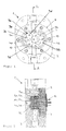
- the rotary piston counter 1 shown in FIG. 1 has an in a housing 2 arranged measuring chamber 6 with two interlocking lemniscate-shaped displacers 3a, 3b on.
- the displacers 3a, 3b sit on parallel shafts 4a, 4b and are non-rotatably connected to them Gears 5a, 5b in a staggered manner by approximately 90 ° to each other Location forced.
- the displacers have one indented middle area 3c and extended end areas 3d on whose end faces are essentially circular are trained.
- Both the shafts 4a, 4b and the gears 5a, 5b are arranged entirely within the measuring chamber 6 to avoid leakage problems to avoid.
- the contours of indented Middle area 3c and end faces 3d of the displacer 3a, 3b are such that the end faces 3d when rotating the displacer at the constriction areas 3c perform a rolling movement.
- the displacers 3a, 3b are each eccentric with two arranged permanent magnet 10 provided a Scanning the flow measurement using an outside of the Measuring chamber 6 arranged (not shown) measuring device allow by this the number of revolutions the displacement body 3a, 3b is detected.
- the measuring chamber 6 has one end sealed by a sealing ring 7 Seat 9 of a cover plate.
- the shafts 4a, 4b are one-sided stored and each with a terminal collar on the inside the saddle holes 11a, 11b arranged in the measuring chamber 6.
- the waves are 4a, 4b at their ends facing away from the saddle holes 11a, 11b by means of a on the seat 9 (see Fig. 1) attached Cover plate 8 axially secured. That way the measuring chamber 6 e.g. cleaned in a simple way be that the cover plate 8 removed and the waves 4a, 4b with the gears 5a, 5b and the displacers 3a, 3b are removed from the measuring chamber 6.
- the outside of the housing 2 is not mechanically connected the measuring device 4a, 4b connected in the form of a Induction coil or other pulse generator 12 for detecting the Number of revolutions of the displacer 3a, 3b arranged.
Landscapes
- Physics & Mathematics (AREA)
- Fluid Mechanics (AREA)
- General Physics & Mathematics (AREA)
- Measuring Volume Flow (AREA)
Abstract
Description
- Fig. 1
- eine Draufsicht auf eine Messkammer eines erfindungsgemäßen Drehkolbenzählers, und
- Fig. 2
- einen Längsschnitt A-A gemäß der Fig. 1.
Claims (7)
- Durchflussmessgerät (1) mit zwei in einer Messkammer (6) eines Gehäuses (2) in einer Wälzbewegung umlaufenden Verdrängerkörpern (3a,3b), die auf im wesentlichen parallelen Wellen (4a,4b) sitzen und mittels kämmender Zahnräder (5a,5b) zwangsgeführt sind, dadurch gekennzeichnet, dass die Zahnräder (5a,5b) zusammen mit den Verdrängerkörpern (3a,3b) innerhalb der Messkammer (6) angeordnet sind und die Wellen (4a,4b) die Messkammer (6) nicht durchsetzen.
- Durchflussmessgerät nach Anspruch 1, dadurch gekennzeichnet, dass die Verdrängerkörper keulenartig ausgebildet sind.
- Durchflussmessgerät nach einem der Ansprüche 1 oder 2, dadurch gekennzeichnet, dass die Verdrängerkörper einen eingezogenen Mittelbereich (3c) und beidseitig desselben erweiterte Endbereiche (3d) aufweisen.
- Vorrichtung nach einem der Ansprüche 1 bis 3, dadurch gekennzeichnet, dass die Verdrängerkörper zykloidenförmige Wandbereiche aufweisen.
- Durchflussmessgerät nach einem der Ansprüche 1 bis 4, dadurch gekennzeichnet, dass die Verdrängerkörper Lemniskaten-Form haben.
- Durchflussmessgerät nach einem der Ansprüche 1 oder 5, dadurch gekennzeichnet, dass die Wellen (4a,4b) einseitig in Sattellöchern (11a,11b) der Messkammer (6) gelagert sind.
- Durchflussmessgerät nach einem der Ansprüche 1 bis 6, gekennzeichnet durch einen berührungslosen Messwertaufnehmer.
Applications Claiming Priority (2)
| Application Number | Priority Date | Filing Date | Title |
|---|---|---|---|
| DE20020241U | 2000-11-29 | ||
| DE20020241U DE20020241U1 (de) | 2000-11-29 | 2000-11-29 | Drehkolbenzähler |
Publications (2)
| Publication Number | Publication Date |
|---|---|
| EP1211489A2 true EP1211489A2 (de) | 2002-06-05 |
| EP1211489A3 EP1211489A3 (de) | 2003-03-05 |
Family
ID=7949433
Family Applications (1)
| Application Number | Title | Priority Date | Filing Date |
|---|---|---|---|
| EP01124416A Withdrawn EP1211489A3 (de) | 2000-11-29 | 2001-10-11 | Drehkolbenzähler |
Country Status (2)
| Country | Link |
|---|---|
| EP (1) | EP1211489A3 (de) |
| DE (1) | DE20020241U1 (de) |
Cited By (1)
| Publication number | Priority date | Publication date | Assignee | Title |
|---|---|---|---|---|
| DE102004063123A1 (de) * | 2004-12-22 | 2006-07-13 | Gruber, Günther | Kompensatorhahn, Verfahren zum Zapfen von Getränken und Verwendung eines Kompensatorhahnes |
Family Cites Families (3)
| Publication number | Priority date | Publication date | Assignee | Title |
|---|---|---|---|---|
| GB2101219B (en) * | 1981-07-07 | 1984-08-22 | Breckland Meters Limited | Rotary fluid flow meter |
| CH691412A5 (de) * | 1995-11-02 | 2001-07-13 | Avimex Ag | Zahnradvolumenzähler. |
| NL1010006C2 (nl) * | 1998-09-04 | 2000-03-07 | Instromet Bv | Draaizuigerinrichting. |
-
2000
- 2000-11-29 DE DE20020241U patent/DE20020241U1/de not_active Expired - Lifetime
-
2001
- 2001-10-11 EP EP01124416A patent/EP1211489A3/de not_active Withdrawn
Cited By (1)
| Publication number | Priority date | Publication date | Assignee | Title |
|---|---|---|---|---|
| DE102004063123A1 (de) * | 2004-12-22 | 2006-07-13 | Gruber, Günther | Kompensatorhahn, Verfahren zum Zapfen von Getränken und Verwendung eines Kompensatorhahnes |
Also Published As
| Publication number | Publication date |
|---|---|
| EP1211489A3 (de) | 2003-03-05 |
| DE20020241U1 (de) | 2002-01-17 |
Similar Documents
| Publication | Publication Date | Title |
|---|---|---|
| AT400766B (de) | Einrichtung zur volumenmessung strömender medien | |
| EP0491246B1 (de) | Volumensensor für Flüssigkeiten | |
| EP2696176B1 (de) | Zahnraddurchflussmesser | |
| DE2705249A1 (de) | Zahnradmaschine (pumpe oder motor) | |
| DE3147208A1 (de) | Volumenstromsensor nach art eines zahnradmotors | |
| DE2446416C3 (de) | DurchfluBmesser | |
| EP1211489A2 (de) | Drehkolbenzähler | |
| DE3833678C2 (de) | Gerät zum Erkennen und Messen des Durchflusses eines viskosen Mediums durch eine Leitung | |
| DE2458699A1 (de) | Nach dem verdraengerprinzip arbeitender rotations-durchflussmesser fuer fluide | |
| DE4221597A1 (de) | Strömungsmeßvorrichtung, Motor oder Pumpe mit zwei umlaufenden Flügeln | |
| DE19547537C1 (de) | Gerotormotor mit Drehzahlabtastung | |
| DE2756215A1 (de) | Kupplungsvorrichtung zur verbindung des messteils mit dem anzeigeteil von gasmessgeraeten | |
| DE2249952B2 (de) | Hydraulische Zahnradmaschine | |
| DE19808218A1 (de) | Antriebsvorrichtung mit einem Exzentergetriebe zur Definition einer Winkelausgangsstellung | |
| DE2709913C2 (de) | Zahnradpumpe | |
| DE961039C (de) | Apparat zum Messen von Drehgeschwindigkeiten | |
| DE2239580C3 (de) | Wechselgetriebe zum Justieren des Mengenzählwerks eines Volumenzählers | |
| DE3249829C2 (en) | Parallel and internal axis rotary piston engine | |
| DE36429C (de) | Zapfhahn mit Mefseinrichtung | |
| DE1186228B (de) | Drehkolben-Fluessigkeitsmengenzaehler | |
| DE19524377A1 (de) | Prüfpumpe zur Druckerzeugung beim Prüfen von Druckmeßgeräten | |
| DE9416839U1 (de) | Volumenzähler | |
| DE2128919A1 (de) | Durchfluß-Volumenmesser für Flüssigkeiten | |
| DE102024115601A1 (de) | Vorrichtung zur messung eines volumenstroms eines fluids | |
| DE8530573U1 (de) | Vorrichtung zur Ermittlung des Beginns eines Verfalls von bewegten, flüssigkeitsgeschmierten Teilen |
Legal Events
| Date | Code | Title | Description |
|---|---|---|---|
| PUAI | Public reference made under article 153(3) epc to a published international application that has entered the european phase |
Free format text: ORIGINAL CODE: 0009012 |
|
| AK | Designated contracting states |
Kind code of ref document: A2 Designated state(s): AT BE CH CY DE DK ES FI FR GB GR IE IT LI LU MC NL PT SE TR |
|
| AX | Request for extension of the european patent |
Free format text: AL;LT;LV;MK;RO;SI |
|
| PUAL | Search report despatched |
Free format text: ORIGINAL CODE: 0009013 |
|
| AK | Designated contracting states |
Kind code of ref document: A3 Designated state(s): AT BE CH CY DE DK ES FI FR GB GR IE IT LI LU MC NL PT SE TR Designated state(s): AT BE CH CY DE DK ES FI FR GB GR IE IT LI LU MC NL PT SE TR |
|
| AX | Request for extension of the european patent |
Extension state: AL LT LV MK RO SI |
|
| RIC1 | Information provided on ipc code assigned before grant |
Ipc: 7G 01F 3/10 B Ipc: 7G 01F 3/08 A |
|
| STAA | Information on the status of an ep patent application or granted ep patent |
Free format text: STATUS: THE APPLICATION HAS BEEN WITHDRAWN |
|
| 18W | Application withdrawn |
Effective date: 20030424 |