EP1211582A1 - Dispositif de surveillance, de commande et de régulation d'une installation technique de système d'automation de bâtiments - Google Patents
Dispositif de surveillance, de commande et de régulation d'une installation technique de système d'automation de bâtiments Download PDFInfo
- Publication number
- EP1211582A1 EP1211582A1 EP00126131A EP00126131A EP1211582A1 EP 1211582 A1 EP1211582 A1 EP 1211582A1 EP 00126131 A EP00126131 A EP 00126131A EP 00126131 A EP00126131 A EP 00126131A EP 1211582 A1 EP1211582 A1 EP 1211582A1
- Authority
- EP
- European Patent Office
- Prior art keywords
- input
- output module
- field device
- field
- output
- Prior art date
- Legal status (The legal status is an assumption and is not a legal conclusion. Google has not performed a legal analysis and makes no representation as to the accuracy of the status listed.)
- Granted
Links
Images

Classifications
-
- G—PHYSICS
- G05—CONTROLLING; REGULATING
- G05B—CONTROL OR REGULATING SYSTEMS IN GENERAL; FUNCTIONAL ELEMENTS OF SUCH SYSTEMS; MONITORING OR TESTING ARRANGEMENTS FOR SUCH SYSTEMS OR ELEMENTS
- G05B19/00—Program-control systems
- G05B19/02—Program-control systems electric
- G05B19/418—Total factory control, i.e. centrally controlling a plurality of machines, e.g. direct or distributed numerical control [DNC], flexible manufacturing systems [FMS], integrated manufacturing systems [IMS] or computer integrated manufacturing [CIM]
- G05B19/4185—Total factory control, i.e. centrally controlling a plurality of machines, e.g. direct or distributed numerical control [DNC], flexible manufacturing systems [FMS], integrated manufacturing systems [IMS] or computer integrated manufacturing [CIM] characterised by the network communication
-
- G—PHYSICS
- G05—CONTROLLING; REGULATING
- G05B—CONTROL OR REGULATING SYSTEMS IN GENERAL; FUNCTIONAL ELEMENTS OF SUCH SYSTEMS; MONITORING OR TESTING ARRANGEMENTS FOR SUCH SYSTEMS OR ELEMENTS
- G05B19/00—Program-control systems
- G05B19/02—Program-control systems electric
- G05B19/04—Program control other than numerical control, i.e. in sequence controllers or logic controllers
- G05B19/042—Program control other than numerical control, i.e. in sequence controllers or logic controllers using digital processors
- G05B19/0421—Multiprocessor system
-
- G—PHYSICS
- G05—CONTROLLING; REGULATING
- G05B—CONTROL OR REGULATING SYSTEMS IN GENERAL; FUNCTIONAL ELEMENTS OF SUCH SYSTEMS; MONITORING OR TESTING ARRANGEMENTS FOR SUCH SYSTEMS OR ELEMENTS
- G05B2219/00—Program-control systems
- G05B2219/20—Pc systems
- G05B2219/25—Pc structure of the system
- G05B2219/25014—Fieldbus general name of bus connected to machines, detectors, actuators
-
- G—PHYSICS
- G05—CONTROLLING; REGULATING
- G05B—CONTROL OR REGULATING SYSTEMS IN GENERAL; FUNCTIONAL ELEMENTS OF SUCH SYSTEMS; MONITORING OR TESTING ARRANGEMENTS FOR SUCH SYSTEMS OR ELEMENTS
- G05B2219/00—Program-control systems
- G05B2219/20—Pc systems
- G05B2219/25—Pc structure of the system
- G05B2219/25016—Eiba bus, european installation bus association, ib installation bus
-
- G—PHYSICS
- G05—CONTROLLING; REGULATING
- G05B—CONTROL OR REGULATING SYSTEMS IN GENERAL; FUNCTIONAL ELEMENTS OF SUCH SYSTEMS; MONITORING OR TESTING ARRANGEMENTS FOR SUCH SYSTEMS OR ELEMENTS
- G05B2219/00—Program-control systems
- G05B2219/20—Pc systems
- G05B2219/25—Pc structure of the system
- G05B2219/25056—Automatic configuration of monitoring, control system as function of operator input, events
-
- G—PHYSICS
- G05—CONTROLLING; REGULATING
- G05B—CONTROL OR REGULATING SYSTEMS IN GENERAL; FUNCTIONAL ELEMENTS OF SUCH SYSTEMS; MONITORING OR TESTING ARRANGEMENTS FOR SUCH SYSTEMS OR ELEMENTS
- G05B2219/00—Program-control systems
- G05B2219/20—Pc systems
- G05B2219/25—Pc structure of the system
- G05B2219/25428—Field device
-
- G—PHYSICS
- G05—CONTROLLING; REGULATING
- G05B—CONTROL OR REGULATING SYSTEMS IN GENERAL; FUNCTIONAL ELEMENTS OF SUCH SYSTEMS; MONITORING OR TESTING ARRANGEMENTS FOR SUCH SYSTEMS OR ELEMENTS
- G05B2219/00—Program-control systems
- G05B2219/20—Pc systems
- G05B2219/26—Pc applications
- G05B2219/2642—Domotique, domestic, home control, automation, smart house
-
- G—PHYSICS
- G05—CONTROLLING; REGULATING
- G05B—CONTROL OR REGULATING SYSTEMS IN GENERAL; FUNCTIONAL ELEMENTS OF SUCH SYSTEMS; MONITORING OR TESTING ARRANGEMENTS FOR SUCH SYSTEMS OR ELEMENTS
- G05B2219/00—Program-control systems
- G05B2219/30—Nc systems
- G05B2219/31—From computer integrated manufacturing till monitoring
- G05B2219/31121—Fielddevice, field controller, interface connected to fieldbus
-
- G—PHYSICS
- G05—CONTROLLING; REGULATING
- G05B—CONTROL OR REGULATING SYSTEMS IN GENERAL; FUNCTIONAL ELEMENTS OF SUCH SYSTEMS; MONITORING OR TESTING ARRANGEMENTS FOR SUCH SYSTEMS OR ELEMENTS
- G05B2219/00—Program-control systems
- G05B2219/30—Nc systems
- G05B2219/31—From computer integrated manufacturing till monitoring
- G05B2219/31135—Fieldbus
Definitions
- the invention relates to a method and a device according to the Preambles of claims 1 and 8.
- Such devices are suitable, for example, for monitoring and control and / or regulation of process variables in complex technical systems, whereby exemplary heating, ventilation and air conditioning systems, access and Fire monitoring systems or general building automation systems - the are also referred to as building management systems - be mentioned in which In particular, indoor climate sizes can also be influenced.
- Building automation systems are usually a variety of so-called To operate field devices such as sensors and actuators.
- Bus systems and Technologies include LON or LonWorks® from ECHELON, the European installation bus EIB or the one defined according to German standard DIN 19245 PROFIBUS.
- optical data communication channels or a radio network can be used, for example a fiber optic network or a cellular telephone network, such as GSM or UMTS.
- EP 416 891 A2 proposes a device which is used to operate Field devices used interface units that are connected to a common Data bus are coupled.
- An interface unit is now from a predetermined one Type and thus capable of exactly a certain type of field device, typically Analog input, analog output, digital input or digital output to operate.
- An output driver circuit for an interface unit is known from EP 335 743 A2 known, which has connection points, both as a signal output as well as Signal input can be used for devices.
- EP 606 335 a control system with a central receiver is known from EP 606 335 known that is connected to a variety of control units.
- Process data are can be detected by scanning units, which data is preferably transmitted wirelessly to the transmit central recipient.
- the invention has for its object a method for automatic Commissioning and integration of field devices of a building management system specify, and to create a facility for performing the method.
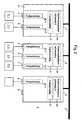
- 1 means a communication medium for connecting units 2, 3 and 4 an arrangement for monitoring, controlling and / or regulating a operational system of a building.
- a first unit 2 and a second unit 3 are each a control unit. and / or control device.
- a third unit 4 is an input / output unit for operation of field devices 5.
- the input / output unit 4 is in several input / output modules divided, which are advantageously connected to one another via a bus system 6.
- a bus system 6 In the Drawing is a first copy of the input / output module with 7, a second Copy with 8 and a third copy with 9.
- the number of over Bus system interconnected copies 7, 8 or 9 of the input / output module is not limited to only three as shown in FIG. 1.
- the first copy 7 advantageously has within the input / output unit 4 compared to the other copies 8 and 9 of the input / output modules via one Expanded functionality by the input / output module 7 exchanging data between the higher-level communication medium 1 and the bus system 6 Input / output unit 4 enables different types of signal carriers if required and different types of data transmission protocols are coordinated. Due to the expanded functionality, the first copy 7 serves within the input / output unit 4 as the basic module, the second copy 8 and the third Copy 9 within the input / output unit 4 each as an expansion module work.
- the first copy 7 of the input / output module advantageously has operating means 10 for a user interface.
- the input / output module 7 comprises the operating means 10 also a connection for a screen terminal or a mobile computer.
- the bus system 6 also has means for feeding the copies 7, 8 and 9 of the input / output module, and / or means for supplying the connected Field devices 5.
- the input / output unit 4 shows the first copy 7 of the input / output module, which acts as the basic module Power supply unit for energy supply via the bus system 6.
- the first unit 2 is over another Communication medium 15 with a higher-level system - for example with a control center, not shown in the drawing - connected. If necessary, that is second unit 3 with a screen terminal or a mobile computer 16 connected.
- the input / output module 7, 8 or 9 advantageously has a plurality of connection points in each case A, B and C for field devices 5. Basically, the number of implemented Connection points per input / output module 7, 8 or 9 can be selected within wide limits and on permissible module costs, space requirements and on the expected data flow per To coordinate time unit. For building automation systems, eight are advantageous or sixteen connection points per input / output module 7, 8 or 9.
- connection points A, B and C are basically identical and universal can be used as an input port and as an output port, i.e. bidirectional and for analog Signals and digital signals.
- the connection point A, B or C advantageously has three each Connection points for the field device 5.
- the universal connection point A, B or C can therefore be used for a variety of field device types, namely for sensors or Actuators, i.e. for field devices with analog input, analog output, digital input or digital output, each with or without supply via connection point A, B or C.
- the field device 5 is two-wire or three-wire with the Connection point A, B or C connected (Fig. 5). If required, the field device 5 is included connected several connection points, for example, if that Field device 5 is an actuator with position feedback, with the control signal then Benefit issued at a first connection point A and at a second A state or the current position of the actuator at the same time is read.
- the field device 5 is typically a sensor for detecting a process variable or an actuator for influencing a process variable.
- connection points A, B or C of a copy 7, 8 or 9 of the input / output module are connected: a temperature sensor 5.1, a humidity sensor 5.2, an actuator 5.3 for a ventilation flap, a gas sensor 5.4, a switch 5.5 and an actuator 5.6 with position feedback, which the connection points A and B of Input / output module 9 required.
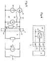
- essential structural elements are of the copy 7, 8 or 9 of the input / output module shown in FIG. 2.
- the copy 7, 8 or 9 of the input / output module has adjustable Communication addresses 20 and a memory area 21 for storing the configurable functionality of the corresponding copy 7, 8 or 9 of the input / output module.
- Each of the copies 7, 8 and 9 of the input / output module advantageously has a variable 22.A or for each of its connection points A, B and C. 22.B or 22.C to save the configurable field device type that corresponds to the corresponds to the connection point A, B or C assigned field device 5.
- the corresponds Port A, B or C each have a data point to which data signals are output, or from which data signals are read.
- Advantageous are several, logical related data points through software of the input / output unit 4 and also by software of the regulation and / or control device 2 or 3 (FIG. 1) to an input / output object can be summarized, in a special case a certain input / output object is assigned to a single data point.
- the communication addresses 20 for each input / output object of the Copy 7, 8 or 9 a physical address, which advantageously also a logical address is assigned.
- the physical address a first component KB assigned to the base module, a second component KE assigned to the expansion module and a third component Component KO assigned to input / output object.
- An input / output object therefore advantageously has a unique 4 in the input / output unit physical address "KB.KE.KO".
- the KE component for the expansion module is then eliminated, if the input / output object is assigned to the basic module.
- At least the two of them Components KE and KO are in an advantageous implementation of the input / output unit 4 through the corresponding copies 7, 8 or 9 of the input / output module automatically assigned, the component KE being exemplary the physical position - order - of item 7, 8 or 9 is determined.
- the automatic assignment of the communication addresses 20 or the two Components KE and KO are advantageously carried out during commissioning of the input / output unit.
- the input / output unit is in particular in a phase of commissioning 4 - those of those to be connected to copy 7, 8 or 9 connected field devices 5 dependent functionality of the copy 7, 8 or 9 stored.
- the functionality of the Copy 7, 8 or 9 significantly determined.
- variable 22.A or 22.B or 22.C is - with advantage in a phase of Commissioning of the input / output unit 4 - that of the at the connection point A, B or C of the copy 7, 8 or 9 to be connected or connected Field device 5 dependent field device type saved. Also through the saved The field device type is the mode of operation of the, related to the connection point A, B or C. Copy 7, 8 or 9 significantly determined.
- a class or a range of values for the field device type is of the expected variety dependent on permissible field devices 5.
- the class mentioned includes examples at least the values "sensor with electrical signal source (active sensor)”, “sensor without electrical signal source (passive sensor) ",” actuator with feedback “and “Actuator without feedback”.
- Range of values and character set e.g. digital or analog signals.
- a first function block 30 enables communication via the bus system 6 (Fig. 2) guaranteed.
- the first function block 30 also advantageously takes over the input / output module Communication between the bus system 6 and the communication medium 1 (Fig. 1).
- a second function block 31 assigns the input / output module in a configuration phase the intended functionality and ensures this in one Operating phase.
- a third function block 32 compares those in the configuration phase in the input / output module stored data with measurement data, wherein the measurement data by the input / output module by measurements on the connected field device 5 be determined automatically.
- a fourth function block 33 generates a status log, on the one hand via essential parameters or states of the input / output module and on the other hand via essential parameters or states of the connected field device 5.
- the fourth Function block 33 also advantageously logs from third function block 32 detected wiring errors regarding the connection points A, B and C (Fig. 2).
- the status report is created and included during commissioning
- a statement about the parameters and the functionality of the input / output module after the configuration phase and another statement about Operational readiness or the state after a test phase the is carried out after the configuration phase, and after - if it was successful - the connected field device 5 completely in the input / output unit is involved.
- the protocol is advantageously sent to a mobile computer via the operating means 10 or the terminal 16 (Fig. 1) issued.
- a fifth function block 34 is used to process and process signals from and to the connection point A, B or C (FIG. 2) of the field device 5.
- Function block 30, 31, 32, 33 or 34 can be used as an electronic circuit or at least partially in software as a process, program piece or routine be realized, the function block in a software version also includes the target hardware.
- At least some of the function blocks 30, 31, 32, 33 or 34 are advantageously used as so-called "Application-Specific Integrated Circuit ASIC" implemented.
- connection point A - or B or C - has at least two Terminals 40, 41 and 42 for field device 5: a first Terminal 40 for a reference potential, one with an interface circuit 43 connected second connecting terminal 41 and, if required, one to a source 44 connected third connection terminal 42.
- the interface circuit 43 is of this type trained that both delivered an output signal for the field device 5, as well an input signal supplied by the field device 5 can be received. If necessary, the field device 5 can be fed via the source 44, with the source 44 also Advantage depending on the requirements of the field device 5, a constant voltage or a can supply constant current for feeding the field device 5.
- the effort for connecting the field devices 5 to the input / output unit is particularly low 4 when the terminals 40, 41 and 42 through reliable spring clips are implemented.
- the source 44 is in turn fed via the bus system 6.
- the intended Functionality of the input / output module 7, 8 or 9 and the field device types for the Input / output module 7, 8 or 9 provided field devices 5 (Fig. 2), where the necessary information with advantage via the operating means 10 (Fig. 1) in the input / output unit 4 can be stored, with the operating means 10 at If a mobile computer is required.
- the information at least partially also via the communication medium 1 in the input / output unit 4 can be loaded, the mobile computer 16 being used as an example.
- the definition of a component of the communication addresses 20 takes place at the Commissioning if necessary already in the configuration phase.
- Commissioning therefore begins with a configuration phase in which the after the Planning of the system defined parameters and the functionality of the input / output unit 4 can be stored in the input / output unit 4. Commissioning is completed with the successful test phase in which the connected Field devices 5 automatically measured electrically and the data obtained with the configured data can be compared.
- Certain types of field devices - such as resistance sensors - are in the test phase practically verifiable with 100% certainty.
- An advantageous method for commissioning the input / output unit 4 and thus the device for controlling and / or regulating process variables by means of the Field devices 4 have at least the following method steps: a first step, in which the input / output module 7, 8 or 9 an address or an address range is assigned. A second step, in which the functionality of the input / output module 7, 8 or 9 is configured, and a third step in which the Field device type of a connected field device 5 is automatically verified.
- the proposed input / output unit 4 enables the proposed advantageous essentially automatic commissioning, which with relatively little time can be practically carried out without special knowledge.
- test phase - or parts of it - also after the Commissioning can be carried out automatically if required. This can cause interference be recognized early on in the system.
Landscapes
- Engineering & Computer Science (AREA)
- Physics & Mathematics (AREA)
- Automation & Control Theory (AREA)
- General Physics & Mathematics (AREA)
- Quality & Reliability (AREA)
- Manufacturing & Machinery (AREA)
- General Engineering & Computer Science (AREA)
- Air Conditioning Control Device (AREA)
- Programmable Controllers (AREA)
- Selective Calling Equipment (AREA)
- Alarm Systems (AREA)
- Burglar Alarm Systems (AREA)
- Maintenance And Inspection Apparatuses For Elevators (AREA)
Priority Applications (3)
| Application Number | Priority Date | Filing Date | Title |
|---|---|---|---|
| EP00126131A EP1211582B1 (fr) | 2000-11-30 | 2000-11-30 | Dispositif de surveillance, de commande et de régulation d'une installation technique de système d'automation de bâtiments |
| AT00126131T ATE241162T1 (de) | 2000-11-30 | 2000-11-30 | Anordnung zur überwachung, steuerung und regelung einer betriebstechnischen anlage eines gebäudes |
| DE50002284T DE50002284D1 (de) | 2000-11-30 | 2000-11-30 | Anordnung zur Überwachung, Steuerung und Regelung einer betriebstechnischen Anlage eines Gebäudes |
Applications Claiming Priority (1)
| Application Number | Priority Date | Filing Date | Title |
|---|---|---|---|
| EP00126131A EP1211582B1 (fr) | 2000-11-30 | 2000-11-30 | Dispositif de surveillance, de commande et de régulation d'une installation technique de système d'automation de bâtiments |
Publications (2)
| Publication Number | Publication Date |
|---|---|
| EP1211582A1 true EP1211582A1 (fr) | 2002-06-05 |
| EP1211582B1 EP1211582B1 (fr) | 2003-05-21 |
Family
ID=8170532
Family Applications (1)
| Application Number | Title | Priority Date | Filing Date |
|---|---|---|---|
| EP00126131A Expired - Lifetime EP1211582B1 (fr) | 2000-11-30 | 2000-11-30 | Dispositif de surveillance, de commande et de régulation d'une installation technique de système d'automation de bâtiments |
Country Status (3)
| Country | Link |
|---|---|
| EP (1) | EP1211582B1 (fr) |
| AT (1) | ATE241162T1 (fr) |
| DE (1) | DE50002284D1 (fr) |
Cited By (17)
| Publication number | Priority date | Publication date | Assignee | Title |
|---|---|---|---|---|
| EP1500992A1 (fr) * | 2003-07-21 | 2005-01-26 | Siemens Building Technologies AG | Dispositif de commande d'appareils de terrain pour une installation technique dans un système d'automatisation de bâtiments |
| WO2006013021A3 (fr) * | 2004-07-30 | 2006-04-20 | Abb Patent Gmbh | Procede et dispositif pour verifier de maniere fonctionnelle un appareil de champ avant sa mise en marche |
| WO2006089760A1 (fr) | 2005-02-24 | 2006-08-31 | Vega Grieshaber Kg | Systeme de bus de terrain pour la communication sans fil |
| EP1734427A1 (fr) * | 2005-06-17 | 2006-12-20 | Honeywell Technologies Sarl ECC | Module d'entrée-sortie utilisable dans un système technique de bâtiment et système technique de bâtiment correspondant |
| EP1762918A1 (fr) | 2005-09-09 | 2007-03-14 | Omron Corporation | Appareil terminal à distance pour contrôleur programmable |
| DE102006017243A1 (de) * | 2006-04-12 | 2007-10-18 | Vega Grieshaber Kg | Sende-Empfangsgerät zur Übertragung von Feldgerätsignalen |
| WO2008015262A1 (fr) * | 2006-08-02 | 2008-02-07 | Siemens Schweiz Ag | Procédé de transmission asynchrone en série de données dans un dispositif pour la surveillance, la commande et la régulation d'une installation technique fonctionnelle d'un bâtiment |
| US7442068B2 (en) | 2004-09-24 | 2008-10-28 | Siemens Schweiz Ag | Electrical device having a base and an electrical module |
| WO2008145170A1 (fr) * | 2007-05-31 | 2008-12-04 | Siemens Aktiengesellschaft | Procédé pour configurer un système d'automatisation |
| EP1950536A3 (fr) * | 2006-11-27 | 2009-01-21 | VEGA Grieshaber KG | Adaptateur d'interface |
| US7885610B2 (en) | 2006-04-12 | 2011-02-08 | Vega Grieshaber Kg | Transceiver for wireless transmission of field device signals |
| US7962100B2 (en) | 2005-02-24 | 2011-06-14 | Vega Grieshaber Kg | Data transmission system for wireless communication |
| WO2012131422A1 (fr) * | 2011-03-31 | 2012-10-04 | Abb Technology Ltd | Procédé de conception et de construction et de diagnostic d'un dispositif de champ et système correspondant |
| CN103149039A (zh) * | 2012-12-21 | 2013-06-12 | 党亚峰 | 一种中央空调系统节能评估系统 |
| DE102012111018A1 (de) * | 2012-11-15 | 2014-05-15 | Systemplan GmbH | Mehrkanaliges Messdatenerfassungsgerät |
| US8923286B2 (en) | 2009-09-23 | 2014-12-30 | Phoenix Contact Gmbh & Co. Kg | Method and apparatus for safety-related communication in a communication network of an automation system |
| EP2421344A3 (fr) * | 2010-08-20 | 2017-03-22 | Rockwell Automation Technologies, Inc. | Dispositifs d'entrée/sortie dotés d'une fonctionnalité reconfigurable |
Families Citing this family (4)
| Publication number | Priority date | Publication date | Assignee | Title |
|---|---|---|---|---|
| DE102004015227A1 (de) * | 2004-03-24 | 2005-10-27 | Siemens Ag | Elektrisches Feldgerät |
| ATE504870T1 (de) | 2007-02-09 | 2011-04-15 | Siemens Ag | Verfahren zum einbinden von netzwerkknoten |
| DE102009029933A1 (de) * | 2009-06-19 | 2010-12-23 | Honeywell Technologies S.A.R.L. | Gebäudemanagementsystem |
| US10175148B2 (en) * | 2015-10-12 | 2019-01-08 | Epro Gmbh | Universal sensor interface for machine monitoring system |
Citations (3)
| Publication number | Priority date | Publication date | Assignee | Title |
|---|---|---|---|---|
| EP0345493A1 (fr) * | 1988-06-08 | 1989-12-13 | Landis & Gyr Technology Innovation AG | Dispositif de surveillance, de commande et de régulation d'une installation technique de systèmes d'automation de bâtiments |
| US5980078A (en) * | 1997-02-14 | 1999-11-09 | Fisher-Rosemount Systems, Inc. | Process control system including automatic sensing and automatic configuration of devices |
| US6064312A (en) * | 1998-07-31 | 2000-05-16 | Hewlett-Packard Company | Method and apparatus for automatic verification of measurement probe functionality and compensation |
-
2000
- 2000-11-30 DE DE50002284T patent/DE50002284D1/de not_active Expired - Lifetime
- 2000-11-30 EP EP00126131A patent/EP1211582B1/fr not_active Expired - Lifetime
- 2000-11-30 AT AT00126131T patent/ATE241162T1/de not_active IP Right Cessation
Patent Citations (3)
| Publication number | Priority date | Publication date | Assignee | Title |
|---|---|---|---|---|
| EP0345493A1 (fr) * | 1988-06-08 | 1989-12-13 | Landis & Gyr Technology Innovation AG | Dispositif de surveillance, de commande et de régulation d'une installation technique de systèmes d'automation de bâtiments |
| US5980078A (en) * | 1997-02-14 | 1999-11-09 | Fisher-Rosemount Systems, Inc. | Process control system including automatic sensing and automatic configuration of devices |
| US6064312A (en) * | 1998-07-31 | 2000-05-16 | Hewlett-Packard Company | Method and apparatus for automatic verification of measurement probe functionality and compensation |
Cited By (26)
| Publication number | Priority date | Publication date | Assignee | Title |
|---|---|---|---|---|
| EP1500992A1 (fr) * | 2003-07-21 | 2005-01-26 | Siemens Building Technologies AG | Dispositif de commande d'appareils de terrain pour une installation technique dans un système d'automatisation de bâtiments |
| WO2006013021A3 (fr) * | 2004-07-30 | 2006-04-20 | Abb Patent Gmbh | Procede et dispositif pour verifier de maniere fonctionnelle un appareil de champ avant sa mise en marche |
| US7442068B2 (en) | 2004-09-24 | 2008-10-28 | Siemens Schweiz Ag | Electrical device having a base and an electrical module |
| WO2006089760A1 (fr) | 2005-02-24 | 2006-08-31 | Vega Grieshaber Kg | Systeme de bus de terrain pour la communication sans fil |
| CN101120543B (zh) * | 2005-02-24 | 2012-09-26 | Vega格里沙贝两合公司 | 用于数据传输的系统和方法,控制设备 |
| US7962100B2 (en) | 2005-02-24 | 2011-06-14 | Vega Grieshaber Kg | Data transmission system for wireless communication |
| EP1734427A1 (fr) * | 2005-06-17 | 2006-12-20 | Honeywell Technologies Sarl ECC | Module d'entrée-sortie utilisable dans un système technique de bâtiment et système technique de bâtiment correspondant |
| DE102005028187A1 (de) * | 2005-06-17 | 2006-12-28 | Honeywell Technologies Sarl | Ein- und Ausgabemodul, das für ein gebäudetechnisches System geeignet ist und ein dazugehöriges gebäudetechnisches System |
| US7562164B2 (en) | 2005-09-09 | 2009-07-14 | Omron Corporation | Remote terminal apparatus for programmable controller |
| EP1762918A1 (fr) | 2005-09-09 | 2007-03-14 | Omron Corporation | Appareil terminal à distance pour contrôleur programmable |
| DE102006017243A1 (de) * | 2006-04-12 | 2007-10-18 | Vega Grieshaber Kg | Sende-Empfangsgerät zur Übertragung von Feldgerätsignalen |
| US7885610B2 (en) | 2006-04-12 | 2011-02-08 | Vega Grieshaber Kg | Transceiver for wireless transmission of field device signals |
| DE102006017243B4 (de) * | 2006-04-12 | 2011-09-15 | Vega Grieshaber Kg | Sende-Empfangsgerät zur drahtlosen Übertragung von Feldgerätesignalen |
| WO2008015262A1 (fr) * | 2006-08-02 | 2008-02-07 | Siemens Schweiz Ag | Procédé de transmission asynchrone en série de données dans un dispositif pour la surveillance, la commande et la régulation d'une installation technique fonctionnelle d'un bâtiment |
| EP1887446A1 (fr) * | 2006-08-02 | 2008-02-13 | Siemens Aktiengesellschaft | Procédé destiné à la transmission asynchrone sérielle de données dans un dispositif de contrôle, de commande et de régulation d'une installation technique industrielle d'un bâtiment |
| US8150462B2 (en) | 2006-11-27 | 2012-04-03 | Vega Grieshaber Kg | Connection box |
| EP1950536A3 (fr) * | 2006-11-27 | 2009-01-21 | VEGA Grieshaber KG | Adaptateur d'interface |
| EP2944927A1 (fr) * | 2006-11-27 | 2015-11-18 | VEGA Grieshaber KG | Boitier de raccordement |
| WO2008145170A1 (fr) * | 2007-05-31 | 2008-12-04 | Siemens Aktiengesellschaft | Procédé pour configurer un système d'automatisation |
| US8923286B2 (en) | 2009-09-23 | 2014-12-30 | Phoenix Contact Gmbh & Co. Kg | Method and apparatus for safety-related communication in a communication network of an automation system |
| DE102009042354C5 (de) * | 2009-09-23 | 2017-07-13 | Phoenix Contact Gmbh & Co. Kg | Verfahren und Vorrichtung zur sicherheitsgerichteten Kommunikation im Kommunikations-Netzwerk einer Automatisierungs-Anlage |
| EP2421344A3 (fr) * | 2010-08-20 | 2017-03-22 | Rockwell Automation Technologies, Inc. | Dispositifs d'entrée/sortie dotés d'une fonctionnalité reconfigurable |
| WO2012131422A1 (fr) * | 2011-03-31 | 2012-10-04 | Abb Technology Ltd | Procédé de conception et de construction et de diagnostic d'un dispositif de champ et système correspondant |
| CN103748524A (zh) * | 2011-03-31 | 2014-04-23 | Abb技术有限公司 | 工程设计并诊断现场装置的方法及其系统 |
| DE102012111018A1 (de) * | 2012-11-15 | 2014-05-15 | Systemplan GmbH | Mehrkanaliges Messdatenerfassungsgerät |
| CN103149039A (zh) * | 2012-12-21 | 2013-06-12 | 党亚峰 | 一种中央空调系统节能评估系统 |
Also Published As
| Publication number | Publication date |
|---|---|
| EP1211582B1 (fr) | 2003-05-21 |
| DE50002284D1 (de) | 2003-06-26 |
| ATE241162T1 (de) | 2003-06-15 |
Similar Documents
| Publication | Publication Date | Title |
|---|---|---|
| EP1211582B1 (fr) | Dispositif de surveillance, de commande et de régulation d'une installation technique de système d'automation de bâtiments | |
| EP1956455B1 (fr) | Méthode pour intégrer des noeuds de réseau | |
| DE10026918B4 (de) | Virtueller Netzwerkadapter | |
| DE102004052075A1 (de) | Knoten für ein Bus-Netzwerk, Bus-Netzwerk und Verfahren zum Konfigurieren des Netzwerks | |
| DE102009045055B4 (de) | Verfahren zum Konfigurieren einer Feldbusschnittstelle | |
| EP0890242A1 (fr) | Procede pour determiner des decalages de potentiel entre modules electroniques d'un reseau a bus filaire | |
| WO2003027629A1 (fr) | Procede de realisation d'un telediagnostic sur un vehicule automobile, module de diagnostic de vehicule et centre de services | |
| WO2007137708A1 (fr) | Appareil et procédé d'adressage et convertisseurs | |
| EP4062591B1 (fr) | Procédé de surveillance de la communication sur un bus de communication, dispositif électronique pour connexion à un bus de communication ainsi que dispositif de surveillance central pour connexion à un bus de communication | |
| DE4216242C2 (de) | Identifizierung von Sensoren / Aktuatoren in Bussystemen | |
| WO2022018131A1 (fr) | Procédé de couplage et d'accouplement d'un capteur, et réseau de communication | |
| EP3861412B1 (fr) | Dispositif agrégateur pour un accès unifié à une pluralité de segments de réseau d'un système de bus de terrain | |
| EP3497524A1 (fr) | Sous-programme d'initialisation automatique dans un systeme d'automatisation | |
| EP0823803A1 (fr) | Dispositif d'accès à un appareil connecté à un réseau local à travers un réseau public | |
| EP1199846A1 (fr) | Procédé de configuration automatique d'un appareil dans un bus de secteur | |
| DE19917102A1 (de) | Projektierungs- und Diagnoseeinrichtung für eine elektrische Anlage | |
| WO2023170198A1 (fr) | Dispositif comprenant un appareil de communication pour le transfert de données par l'intermédiaire d'un bus de transfert de données, et système de transfert de données comprenant des dispositifs de ce type | |
| DE10331307A1 (de) | Vorrichtung und Verfahren sowie Sicherheitsmodul zur Sicherung eines Datenzugriffs eines Kommunikationsteilnehmers auf mindestens eine Automatisierungskomponente eines Automatisierungssystems | |
| EP1840684A1 (fr) | Dispositif et système d'automatisation dont les composants peuvent communiquer par liaison radio utilisant des modules radio détachables | |
| EP3729737B1 (fr) | Composant de bus de terrain comprenant un élément de réglage pour la configuration de la transmission de données à un nuage | |
| US7013186B2 (en) | Switchgear cabinet monitoring and control arrangement | |
| EP3948448A1 (fr) | Procédé de modification d'un logiciel de commande d'un système d'automatisation | |
| DE102007039427A1 (de) | Steuerknoten für ein Netzwerk aus Steuerknoten | |
| EP4262155A1 (fr) | Dispositif et procédé de connexion d'un appareil de terrain à un système de communication | |
| DE102006051980B4 (de) | Feldkommunikationssystem |
Legal Events
| Date | Code | Title | Description |
|---|---|---|---|
| PUAI | Public reference made under article 153(3) epc to a published international application that has entered the european phase |
Free format text: ORIGINAL CODE: 0009012 |
|
| AK | Designated contracting states |
Kind code of ref document: A1 Designated state(s): AT BE CH CY DE DK ES FI FR GB GR IE IT LI LU MC NL PT SE TR |
|
| AX | Request for extension of the european patent |
Free format text: AL;LT;LV;MK;RO;SI |
|
| 17P | Request for examination filed |
Effective date: 20020708 |
|
| GRAH | Despatch of communication of intention to grant a patent |
Free format text: ORIGINAL CODE: EPIDOS IGRA |
|
| AKX | Designation fees paid |
Designated state(s): AT BE CH CY DE DK ES FI FR GB GR IE IT LI LU MC NL PT SE TR |
|
| GRAH | Despatch of communication of intention to grant a patent |
Free format text: ORIGINAL CODE: EPIDOS IGRA |
|
| GRAA | (expected) grant |
Free format text: ORIGINAL CODE: 0009210 |
|
| AK | Designated contracting states |
Designated state(s): AT BE CH CY DE DK ES FI FR GB GR IE IT LI LU MC NL PT SE TR |
|
| PG25 | Lapsed in a contracting state [announced via postgrant information from national office to epo] |
Ref country code: IE Free format text: LAPSE BECAUSE OF FAILURE TO SUBMIT A TRANSLATION OF THE DESCRIPTION OR TO PAY THE FEE WITHIN THE PRESCRIBED TIME-LIMIT Effective date: 20030521 Ref country code: FI Free format text: LAPSE BECAUSE OF FAILURE TO SUBMIT A TRANSLATION OF THE DESCRIPTION OR TO PAY THE FEE WITHIN THE PRESCRIBED TIME-LIMIT Effective date: 20030521 Ref country code: TR Free format text: LAPSE BECAUSE OF FAILURE TO SUBMIT A TRANSLATION OF THE DESCRIPTION OR TO PAY THE FEE WITHIN THE PRESCRIBED TIME-LIMIT Effective date: 20030521 |
|
| REG | Reference to a national code |
Ref country code: GB Ref legal event code: FG4D Free format text: NOT ENGLISH |
|
| REG | Reference to a national code |
Ref country code: CH Ref legal event code: EP |
|
| REG | Reference to a national code |
Ref country code: IE Ref legal event code: FG4D Free format text: GERMAN |
|
| REF | Corresponds to: |
Ref document number: 50002284 Country of ref document: DE Date of ref document: 20030626 Kind code of ref document: P |
|
| GBT | Gb: translation of ep patent filed (gb section 77(6)(a)/1977) | ||
| PG25 | Lapsed in a contracting state [announced via postgrant information from national office to epo] |
Ref country code: PT Free format text: LAPSE BECAUSE OF FAILURE TO SUBMIT A TRANSLATION OF THE DESCRIPTION OR TO PAY THE FEE WITHIN THE PRESCRIBED TIME-LIMIT Effective date: 20030821 Ref country code: DK Free format text: LAPSE BECAUSE OF FAILURE TO SUBMIT A TRANSLATION OF THE DESCRIPTION OR TO PAY THE FEE WITHIN THE PRESCRIBED TIME-LIMIT Effective date: 20030821 Ref country code: GR Free format text: LAPSE BECAUSE OF FAILURE TO SUBMIT A TRANSLATION OF THE DESCRIPTION OR TO PAY THE FEE WITHIN THE PRESCRIBED TIME-LIMIT Effective date: 20030821 |
|
| PG25 | Lapsed in a contracting state [announced via postgrant information from national office to epo] |
Ref country code: ES Free format text: LAPSE BECAUSE OF FAILURE TO SUBMIT A TRANSLATION OF THE DESCRIPTION OR TO PAY THE FEE WITHIN THE PRESCRIBED TIME-LIMIT Effective date: 20030901 |
|
| REG | Reference to a national code |
Ref country code: SE Ref legal event code: TRGR |
|
| PG25 | Lapsed in a contracting state [announced via postgrant information from national office to epo] |
Ref country code: MC Free format text: LAPSE BECAUSE OF NON-PAYMENT OF DUE FEES Effective date: 20031130 Ref country code: AT Free format text: LAPSE BECAUSE OF NON-PAYMENT OF DUE FEES Effective date: 20031130 Ref country code: LU Free format text: LAPSE BECAUSE OF NON-PAYMENT OF DUE FEES Effective date: 20031130 Ref country code: BE Free format text: LAPSE BECAUSE OF NON-PAYMENT OF DUE FEES Effective date: 20031130 Ref country code: CY Free format text: LAPSE BECAUSE OF FAILURE TO SUBMIT A TRANSLATION OF THE DESCRIPTION OR TO PAY THE FEE WITHIN THE PRESCRIBED TIME-LIMIT Effective date: 20031130 |
|
| REG | Reference to a national code |
Ref country code: IE Ref legal event code: FD4D Ref document number: 1211582E Country of ref document: IE |
|
| ET | Fr: translation filed | ||
| PLBE | No opposition filed within time limit |
Free format text: ORIGINAL CODE: 0009261 |
|
| STAA | Information on the status of an ep patent application or granted ep patent |
Free format text: STATUS: NO OPPOSITION FILED WITHIN TIME LIMIT |
|
| 26N | No opposition filed |
Effective date: 20040224 |
|
| BERE | Be: lapsed |
Owner name: *SIEMENS BUILDING TECHNOLOGIES A.G. Effective date: 20031130 |
|
| REG | Reference to a national code |
Ref country code: CH Ref legal event code: PFA Owner name: SIEMENS BUILDING TECHNOLOGIES AG C-IPR Free format text: SIEMENS BUILDING TECHNOLOGIES AG#BELLERIVESTRASSE 36#8008 ZUERICH (CH) -TRANSFER TO- SIEMENS BUILDING TECHNOLOGIES AG C-IPR#GUBELSTRASSE 22#6300 ZUG (CH) |
|
| REG | Reference to a national code |
Ref country code: FR Ref legal event code: TP |
|
| REG | Reference to a national code |
Ref country code: CH Ref legal event code: PUE Owner name: SIEMENS AKTIENGESELLSCHAFT Free format text: SIEMENS BUILDING TECHNOLOGIES AG C-IPR#GUBELSTRASSE 22#6300 ZUG (CH) -TRANSFER TO- SIEMENS AKTIENGESELLSCHAFT#WITTELSBACHERPLATZ 2#80333 MUENCHEN (DE) Ref country code: CH Ref legal event code: NV Representative=s name: SIEMENS SCHWEIZ AG |
|
| REG | Reference to a national code |
Ref country code: GB Ref legal event code: 732E Free format text: REGISTERED BETWEEN 20090514 AND 20090520 |
|
| REG | Reference to a national code |
Ref country code: NL Ref legal event code: SD Effective date: 20110318 |
|
| PGFP | Annual fee paid to national office [announced via postgrant information from national office to epo] |
Ref country code: DE Payment date: 20130118 Year of fee payment: 13 Ref country code: CH Payment date: 20130211 Year of fee payment: 13 |
|
| PGFP | Annual fee paid to national office [announced via postgrant information from national office to epo] |
Ref country code: GB Payment date: 20131111 Year of fee payment: 14 Ref country code: FR Payment date: 20131119 Year of fee payment: 14 Ref country code: SE Payment date: 20131107 Year of fee payment: 14 |
|
| PGFP | Annual fee paid to national office [announced via postgrant information from national office to epo] |
Ref country code: IT Payment date: 20131127 Year of fee payment: 14 Ref country code: NL Payment date: 20131105 Year of fee payment: 14 |
|
| REG | Reference to a national code |
Ref country code: CH Ref legal event code: PL |
|
| PG25 | Lapsed in a contracting state [announced via postgrant information from national office to epo] |
Ref country code: LI Free format text: LAPSE BECAUSE OF NON-PAYMENT OF DUE FEES Effective date: 20131130 Ref country code: CH Free format text: LAPSE BECAUSE OF NON-PAYMENT OF DUE FEES Effective date: 20131130 |
|
| REG | Reference to a national code |
Ref country code: DE Ref legal event code: R119 Ref document number: 50002284 Country of ref document: DE Effective date: 20140603 |
|
| PG25 | Lapsed in a contracting state [announced via postgrant information from national office to epo] |
Ref country code: DE Free format text: LAPSE BECAUSE OF NON-PAYMENT OF DUE FEES Effective date: 20140603 |
|
| REG | Reference to a national code |
Ref country code: NL Ref legal event code: V1 Effective date: 20150601 |
|
| GBPC | Gb: european patent ceased through non-payment of renewal fee |
Effective date: 20141130 |
|
| PG25 | Lapsed in a contracting state [announced via postgrant information from national office to epo] |
Ref country code: SE Free format text: LAPSE BECAUSE OF NON-PAYMENT OF DUE FEES Effective date: 20141201 |
|
| REG | Reference to a national code |
Ref country code: SE Ref legal event code: EUG |
|
| REG | Reference to a national code |
Ref country code: FR Ref legal event code: ST Effective date: 20150731 |
|
| PG25 | Lapsed in a contracting state [announced via postgrant information from national office to epo] |
Ref country code: NL Free format text: LAPSE BECAUSE OF NON-PAYMENT OF DUE FEES Effective date: 20150601 |
|
| PG25 | Lapsed in a contracting state [announced via postgrant information from national office to epo] |
Ref country code: GB Free format text: LAPSE BECAUSE OF NON-PAYMENT OF DUE FEES Effective date: 20141130 |
|
| PG25 | Lapsed in a contracting state [announced via postgrant information from national office to epo] |
Ref country code: FR Free format text: LAPSE BECAUSE OF NON-PAYMENT OF DUE FEES Effective date: 20141201 |
|
| PG25 | Lapsed in a contracting state [announced via postgrant information from national office to epo] |
Ref country code: IT Free format text: LAPSE BECAUSE OF NON-PAYMENT OF DUE FEES Effective date: 20141130 |