EP1211878A2 - Verfahren und Vorrichtung zur Anrufumleitung mittels eines Stellvertreter in einem Kommunikationssystem - Google Patents
Verfahren und Vorrichtung zur Anrufumleitung mittels eines Stellvertreter in einem Kommunikationssystem Download PDFInfo
- Publication number
- EP1211878A2 EP1211878A2 EP01000669A EP01000669A EP1211878A2 EP 1211878 A2 EP1211878 A2 EP 1211878A2 EP 01000669 A EP01000669 A EP 01000669A EP 01000669 A EP01000669 A EP 01000669A EP 1211878 A2 EP1211878 A2 EP 1211878A2
- Authority
- EP
- European Patent Office
- Prior art keywords
- terminal
- call forwarding
- call
- message
- communication system
- Prior art date
- Legal status (The legal status is an assumption and is not a legal conclusion. Google has not performed a legal analysis and makes no representation as to the accuracy of the status listed.)
- Granted
Links
Images



Classifications
-
- H—ELECTRICITY
- H04—ELECTRIC COMMUNICATION TECHNIQUE
- H04M—TELEPHONIC COMMUNICATION
- H04M3/00—Automatic or semi-automatic exchanges
- H04M3/42—Systems providing special services or facilities to subscribers
- H04M3/54—Arrangements for diverting calls for one subscriber to another predetermined subscriber
-
- H—ELECTRICITY
- H04—ELECTRIC COMMUNICATION TECHNIQUE
- H04M—TELEPHONIC COMMUNICATION
- H04M7/00—Arrangements for interconnection between switching centres
- H04M7/006—Networks other than PSTN/ISDN providing telephone service, e.g. Voice over Internet Protocol (VoIP), including next generation networks with a packet-switched transport layer
Definitions
- the invention relates to a method and an apparatus for Call forwarding in a multicast communication system of terminals according to the preamble of claim 1.
- LANs Local networks
- multimedia communication systems for example the standard ITU-T H.323 interfaces, necessary Units and processes.
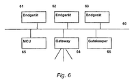
- FIG. 6 shows the basic structure of a device according to H.323 shown.
- the packet-based network 60 With the packet-based network 60 are the end devices 61, 62 and 63, the gateway 64, the gatekeeper 66 and the Multipoint Controll Unit (MCU) 65 connected.
- the end devices 61-63 can communicate with one another via the network 60, To do this, however, they have to register with Gatekeeper 66 and request the transmission capacity (bandwidth) from him.
- the gateway 64 forms the interface of the device other networks.
- the MCU 65 is used in the H.323 standard for conference calls Are defined.
- a computer can be switched off as a terminal and then no longer accessible in the communication system.
- Call forwarding is refining in the H.323 Standard H.450.3 provided, but not the case of one switchable terminal is taken into account. So becomes a Terminal switched off after activating call forwarding, call forwarding is lost.
- the object of the present invention is a method and to provide a device for call forwarding also for disconnectable end devices in a communication system guarantee.
- a variety of end devices connected to a local area network are connected, a call forwarding from a first Terminal activated to a second terminal, an information reported to a proxy unit via call forwarding, whereupon a rerouting of a call for the first terminal based on the transmitted information.
- a computer-controlled device in one Communication system a variety of end devices that with are connected to a local network, also a proxy unit, manages the call forwarding of the end devices. By this method and this device is one Call forwarding even after the first terminal is switched off possible.
- Communication system uses the H.323 protocol. Thereby can use standardized interfaces for communication and procedures are used.
- the proxy unit is a third terminal of the communication system because no additional superordinate units are necessary.
- the substitute unit stores a list of the LAN registered devices. This allows the deputy unit initiate a call forwarding without trying must be undertaken to communicate with the first terminal.
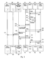
- FIG. 1 A preferred embodiment of the device according to the invention is shown in Fig. 1.
- a PC as a terminal 1 is via its H.323 interface 11 as a proxy client 10 connected to the local area network (LAN) 12.
- Two other end devices 2, 3 are connected to the LAN 12 as clients.
- All Terminals 1 to 3 are connected to the monitoring unit 5, which in turn via a T server 6 and a CSTA3 interface with the deputy unit 7 together with associated Database 8 is connected.
- the activated call forwarding saved by the end devices 1-3 via the monitoring unit 5 and the T server 6 be transferred to the deputy 7.
- the monitoring unit 5 monitors the end devices registered in the LAN, as well all calls and connections in the LAN.
- the T server 6 can for example a central telephone system with a connection to the public or local telephone network or a telephone server for example a "computer telephone integration" (CTI) server with connection to a central telephone system his.
- CTI computer telephone integration
- the arrangement shown in Figure 2 is also called “Third Party "or central solution.
- a more detailed description Such a device is found in the older one Patent application DE 199 47 032.
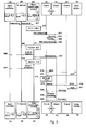
- the message exchange is in each case in the flow diagrams between the terminals 1 to 4, the gatekeeper 9, the monitoring unit 5, the T server 6 and the deputy 7 shown.
- There is an initial and an end state for each unit by the reference character extended by a letter the unit (e.g. terminal 1 in Figure 2: 1A > 1B).
- the following simplifications are also shown in FIGS. 2 to 5 and their description: A message the content unchanged from one unit to the next is passed through, but is only with two arrows provided with a reference number. Simple confirmation messages (e.g. Ack 313) are not described in detail.
- the terminal 2 shows how the terminals 1 to 3 are one after the other through the messages 201, 203, 205, through the messages 202, 204, 206 are confirmed at the monitoring unit 5 register.
- the terminal 1 shares the monitoring unit 5 with its property that it is in local network 12 serves as a proxy client.
- the deputy 7 requests the list of registered Terminal devices via the T server 6 from the monitoring unit 5 from.
- a confirmation message 208 be with the message 209 the list of registered terminals (1 to 3) from the monitoring unit 5 to the representative 7.
- the representative 7 also requests the monitoring unit 5 message 210 to start monitoring the proxy client (Terminal) 1 on.
- the monitoring unit 5 thus has its starting state 5A reaches the final state 5B in FIG. 2.
- condition 5B of the monitoring unit 5 identify the digits 1 to 3 in the dashed box of the monitoring unit 5 The fact that the terminals 1 to 3 in the monitoring unit are registered, and the bold print of the number 1 the The fact that the terminal 1 registers as a proxy client has been.
- Fig. 3 is the activation of the call forwarding of the terminal 2 on the terminal 3, as well as switching off the terminal 2 shown.
- the terminal requests 2 from the gatekeeper 9 to the address of the terminal 3.
- the terminal 2 requests the establishment of a connection with Terminal 3 via the message 303.
- the terminal 3 provides this connection in step 304, whereby the terminal 2 communicates status information, for example restrictions include.
- the terminal 2 solves the Connection to the terminal 3 with the message 305.
- the Message 306 is shared by terminal 2 of monitoring unit 5 active call forwarding from terminal 2 to terminal 3 from Type "immediate call forwarding" with.
- the monitoring unit 5 transmits this information to the terminal 1 with the message 307, whereupon the terminal 1 sends the gatekeeper 9 via a registration request 308 the list of redirected terminals telling. After answer 309 of gatekeeper 9 confirmed the terminal 1 redirects the call to the monitoring unit 5 with message 310. With message 311, the monitoring unit conducts the information of the call forwarding to the Substitute 7 on the T-server 6 further. With the unsubscribe message 312 and its confirmation 313 reports that Terminal 2 from the monitoring unit 5 to after logging off 314 and its confirmation 315 for deregistration from Gatekeeper 9 to cease operation. The only one shown Change from state B to state C of the units in 3 is the switching off of the terminal 2.
- Fig. 4 is an incoming call from a terminal 4 for the terminal 2 is shown in its message sequence, whereby the units for state C change to state D.
- the Terminal 4 sends an access request 401 to gatekeeper 9 and receives with confirmation 402 as destination address "D1 or Proxy ".
- the terminal 4 then generates one in step 403 H.323 call identification number (call ID) HC1.
- call ID HC1 requests the terminal 4 from the terminal 1 in the Message 404 to establish a connection, whereupon the Terminal 1 in request request 405 the bandwidth at Gatekeeper 9 requests and confirmed with message 406 gets.
- the terminal 4 divides the monitoring unit 5 into the message 407 with the H.
- Step 412 replaces C1 with HC1 and sends with the message 413 the information about the connection established between Terminal 1 and terminal 4 to the representative 7 on.
- FIG. 5 shows the diversion of the call from FIG. 4.
- the deputy notifies 7 the monitoring unit 5 from the call forwarding by tell her the new destination address (terminal 3).
- the C1 is replaced by HC1
- the message 503 from the monitoring unit 5 to the terminal 1.
- the terminal 1 calls a message 504 Call forwarding function on the terminal 4, which with the Message 505 is confirmed.
- the terminal 1 confirms the call forwarding to the monitoring unit 5 for HC1, in Step 507 again converts HC1 to C1 to use the Message 508 to confirm call forwarding to Deputy 7 to be forwarded.
- the message 509 informs the terminal 4 of the monitoring unit 5 the call forwarding with detailed information about the call forwarding, which after conversion step 510 in the Message 511 is forwarded to the deputy 7.
- the Step 512 requests the terminal 1 a bandwidth for the Connection to the terminal unit 3 to that with the message 513 is confirmed.
- the establishment of the connection is requested with message 515.
- the terminal 3 makes an access request 516 to the Gatekeeper 9, then the terminal 3 alarms the terminal 4 for the second call ID HC2.
- the terminal 4 solves with the Message 519 the connection to the terminal 1 with the call ID HC1 and finally the connection HC2 between terminal 3 and terminal 4 with the message 520.
- the terminal 1 is also the representative unit and takes over their tasks. This arrangement is also called First-party or stand-alone solution.
Landscapes
- Engineering & Computer Science (AREA)
- Signal Processing (AREA)
- Computer Networks & Wireless Communication (AREA)
- Data Exchanges In Wide-Area Networks (AREA)
- Telephonic Communication Services (AREA)
Abstract
Description
- Fig. 1
- eine schematische Darstellung einer erfindungsgemäßen Vorrichtung mit Stellvertretereinheit,
- Fig. 2
- ein Ablaufdiagramm für eine Initialisierungsphase in einem Kommunikationssystem entsprechend Figur 1,
- Fig. 3
- ein Ablaufdiagramm für das Aktivieren einer Anrufumleitung und Abschalten des ersten Endgerätes in dem Kommunikationssystem aus Figur 2,
- Fig. 4
- ein Ablaufdiagramm für einen ankommenden Anruf Endgerätes in dem Kommunikationssystem aus Figur 3,
- Fig. 5
- ein Ablaufdiagramm für das erfindungsgemäße Umleiten des Anrufes in dem Kommunikationssystem aus Figur 4,
- Fig. 6
- eine schematische Darstellung einer Vorrichtung mit Einheiten gemäß H.323.
- Initialisierung in Fig. 2,
- Aktivieren einer Anrufumleitung in Fig. 3,
- Anruf von einem vierten Endgerät an den Umleitenden in Fig. 4,
- Umleitung des Anrufs in Fig. 5.
Claims (9)
- Verfahren zur Anrufumleitung in einem Kommunikationssystem mit einer Vielzahl von Endgeräten (1 - 4), die mit einem lokalen Netzwerk (LAN) (12) verbunden sind, mit folgenden Schritten:gekennzeichnet durchAktivieren einer Anrufumleitung von einem ersten Endgerät (2) zu einem zweiten Endgerät (3);Übertragen einer Information über die aktivierte Anrufumleitung an eine Stellvertretereinheit (7); undUmleiten eines Anrufs für das erste Endgerät (2) anhand der übertragenen Information.
- Verfahren nach Anspruch 1 dadurch gekennzeichnet, dass das Protokoll H.323 im Kommunikationssystem verwendet wird.
- Verfahren nach Anspruch 1 oder 2 dadurch gekennzeichnet, dass die Stellvertretereinheit ein drittes Endgerät des Kommunikationssystems ist.
- Verfahren nach einem der Ansprüche 1 bis 3 dadurch gekennzeichnet, dass das erste Endgerät abschaltbar ist.
- Verfahren nach einem der Ansprüche 1 bis 4 dadurch gekennzeichnet, dass das Übertragen der Information an die Stellvertretereinheit in einer Protokollschicht oberhalb des H.323 Protokoll erfolgt.
- Verfahren nach Anspruch 5 dadurch gekennzeichnet, dass die Stellvertretereinheit eine Liste der mit dem LAN verbundenen Endgeräte speichert.
- Verfahren nach Anspruch 6 dadurch gekennzeichnet, dass die Stellvertretereinheit die Anrufumleitung steuert.
- Rechnergesteuerte Vorrichtung in einem Kommunikationssystem mit:dadurch gekennzeichnet, dass die Vorrichtung weiter umfasst:einer Vielzahl von Endgeräten, die mit einem lokalen Netzwerk (LAN) verbunden sind;eine Stellvertretereinheit, die Anrufumleitungen der Endgeräte verwaltet.
- Vorrichtung nach Anspruch 8, die zumindest eines der Verfahren 1 bis 7 realisiert.
Applications Claiming Priority (2)
| Application Number | Priority Date | Filing Date | Title |
|---|---|---|---|
| DE10059175A DE10059175A1 (de) | 2000-11-29 | 2000-11-29 | Verfahren und Vorrichtung zur Anrufumleitung mittels eines Stellvertreters in einem Kommunikationssystem |
| DE10059175 | 2000-11-29 |
Publications (3)
| Publication Number | Publication Date |
|---|---|
| EP1211878A2 true EP1211878A2 (de) | 2002-06-05 |
| EP1211878A3 EP1211878A3 (de) | 2003-08-13 |
| EP1211878B1 EP1211878B1 (de) | 2006-01-25 |
Family
ID=7665047
Family Applications (1)
| Application Number | Title | Priority Date | Filing Date |
|---|---|---|---|
| EP01000669A Expired - Lifetime EP1211878B1 (de) | 2000-11-29 | 2001-11-28 | Verfahren und Vorrichtung zur Anrufumleitung mittels eines Stellvertreter in einem Kommunikationssystem |
Country Status (3)
| Country | Link |
|---|---|
| US (1) | US7027435B2 (de) |
| EP (1) | EP1211878B1 (de) |
| DE (2) | DE10059175A1 (de) |
Cited By (2)
| Publication number | Priority date | Publication date | Assignee | Title |
|---|---|---|---|---|
| US9714411B2 (en) | 2004-10-29 | 2017-07-25 | Baxalta GmbH | Animal protein-free media for cultivation of cells |
| US9758568B2 (en) | 2006-01-04 | 2017-09-12 | Baxalta GmbH | Oligopeptide-free cell culture media |
Families Citing this family (28)
| Publication number | Priority date | Publication date | Assignee | Title |
|---|---|---|---|---|
| US8751571B2 (en) | 2001-02-27 | 2014-06-10 | Verizon Data Services Llc | Methods and systems for CPN triggered collaboration |
| US7903796B1 (en) | 2001-02-27 | 2011-03-08 | Verizon Data Services Llc | Method and apparatus for unified communication management via instant messaging |
| US8798251B2 (en) | 2001-02-27 | 2014-08-05 | Verizon Data Services Llc | Methods and systems for computer enhanced conference calling |
| US8750482B2 (en) | 2001-02-27 | 2014-06-10 | Verizon Data Services Llc | Methods and systems for preemptive rejection of calls |
| US8488766B2 (en) | 2001-02-27 | 2013-07-16 | Verizon Data Services Llc | Methods and systems for multiuser selective notification |
| US8467502B2 (en) | 2001-02-27 | 2013-06-18 | Verizon Data Services Llc | Interactive assistant for managing telephone communications |
| US8494135B2 (en) * | 2001-02-27 | 2013-07-23 | Verizon Data Services Llc | Methods and systems for contact management |
| US8774380B2 (en) | 2001-02-27 | 2014-07-08 | Verizon Patent And Licensing Inc. | Methods and systems for call management with user intervention |
| US6976017B1 (en) | 2001-02-27 | 2005-12-13 | Verizon Data Services Inc. | Method and apparatus for context based querying |
| US8488761B2 (en) * | 2001-02-27 | 2013-07-16 | Verizon Data Services Llc | Methods and systems for a call log |
| US8503639B2 (en) | 2001-02-27 | 2013-08-06 | Verizon Data Services Llc | Method and apparatus for adaptive message and call notification |
| US8472606B2 (en) * | 2001-02-27 | 2013-06-25 | Verizon Data Services Llc | Methods and systems for directory information lookup |
| US8472931B2 (en) * | 2002-11-25 | 2013-06-25 | Telesector Resources Group, Inc. | Methods and systems for automatic communication line management based on device location |
| US7912193B2 (en) | 2001-02-27 | 2011-03-22 | Verizon Data Services Llc | Methods and systems for call management with user intervention |
| US8503650B2 (en) | 2001-02-27 | 2013-08-06 | Verizon Data Services Llc | Methods and systems for configuring and providing conference calls |
| US8761363B2 (en) | 2001-02-27 | 2014-06-24 | Verizon Data Services Llc | Methods and systems for automatic forwarding of communications to a preferred device |
| US8873730B2 (en) | 2001-02-27 | 2014-10-28 | Verizon Patent And Licensing Inc. | Method and apparatus for calendared communications flow control |
| US8472428B2 (en) | 2001-02-27 | 2013-06-25 | Verizon Data Services Llc | Methods and systems for line management |
| US6750897B1 (en) | 2001-08-16 | 2004-06-15 | Verizon Data Services Inc. | Systems and methods for implementing internet video conferencing using standard phone calls |
| US9392120B2 (en) | 2002-02-27 | 2016-07-12 | Verizon Patent And Licensing Inc. | Methods and systems for call management with user intervention |
| US7899172B2 (en) | 2003-01-21 | 2011-03-01 | Avaya Canada Corp. | Call forwarding systems, methods and network devices |
| DE10345051B4 (de) * | 2003-09-26 | 2009-04-09 | Siemens Ag | Verfahren zum Aufbau einer Kommunikationsverbindung in einem direkt kommunizierenden Kommunikationsnetzwerk |
| KR101130096B1 (ko) * | 2003-11-21 | 2012-03-28 | 아바야 캐나다 코포레이션 | 네트워크 디바이스들의 백업 |
| US20050157575A1 (en) * | 2003-12-03 | 2005-07-21 | International Business Machines Corporation | Storage device and method |
| US20050144621A1 (en) * | 2003-12-23 | 2005-06-30 | Millbery Trevor A. | CSTA services library |
| US20060067300A1 (en) * | 2004-09-30 | 2006-03-30 | Behrouz Poustchi | System and method for bridge call appearance in distributed peer-to-peer network |
| JP2008113381A (ja) * | 2006-10-31 | 2008-05-15 | Toshiba Corp | 通信システム |
| US8509202B2 (en) * | 2008-08-14 | 2013-08-13 | Koninklijke Philips N.V. | Method for communicating in a network, a system and a primary station therefor |
Family Cites Families (2)
| Publication number | Priority date | Publication date | Assignee | Title |
|---|---|---|---|---|
| US6449260B1 (en) * | 1998-05-01 | 2002-09-10 | Siemens Information And Communication Networks, Inc. | Multimedia automatic call distribution system |
| US6603849B2 (en) * | 1999-08-20 | 2003-08-05 | Ericsson Inc. | System and method for call re-direction in H.323 network |
-
2000
- 2000-11-29 DE DE10059175A patent/DE10059175A1/de not_active Withdrawn
-
2001
- 2001-11-28 DE DE50108773T patent/DE50108773D1/de not_active Expired - Lifetime
- 2001-11-28 EP EP01000669A patent/EP1211878B1/de not_active Expired - Lifetime
- 2001-11-29 US US09/998,066 patent/US7027435B2/en not_active Expired - Lifetime
Cited By (3)
| Publication number | Priority date | Publication date | Assignee | Title |
|---|---|---|---|---|
| US9714411B2 (en) | 2004-10-29 | 2017-07-25 | Baxalta GmbH | Animal protein-free media for cultivation of cells |
| US9809796B2 (en) | 2004-10-29 | 2017-11-07 | Baxalta GmbH | Animal protein-free media for cultivation of cells |
| US9758568B2 (en) | 2006-01-04 | 2017-09-12 | Baxalta GmbH | Oligopeptide-free cell culture media |
Also Published As
| Publication number | Publication date |
|---|---|
| EP1211878A3 (de) | 2003-08-13 |
| US7027435B2 (en) | 2006-04-11 |
| DE50108773D1 (de) | 2006-04-13 |
| US20020136182A1 (en) | 2002-09-26 |
| DE10059175A1 (de) | 2002-06-20 |
| EP1211878B1 (de) | 2006-01-25 |
Similar Documents
| Publication | Publication Date | Title |
|---|---|---|
| EP1211878B1 (de) | Verfahren und Vorrichtung zur Anrufumleitung mittels eines Stellvertreter in einem Kommunikationssystem | |
| DE60014234T2 (de) | System und Verfahren zum Ermöglichen von Fehlertolerante Systeme | |
| DE69827798T2 (de) | Multimedia-Anrufhandhabung | |
| DE10245330B4 (de) | Softwareschalter der verteilte Firewalls für eine Lastteilung von Internet-Telefonie-Verkehr in einem IP-Netz verwendet | |
| DE69615225T2 (de) | Verteilte architektur für dienste eines telefonsystems | |
| DE60036912T2 (de) | System und Verfahren zur Bandbreite-Basierte Codec-Auswahl | |
| EP1492300A1 (de) | Verfahren und Anordnung zum Zugriff auf ein erstes Endgerät eines ersten Kommunikationsnetzwerkes durch einen Kommunikationsknoten in einem zweiten Kommunikationsnetzwerk | |
| DE60212988T2 (de) | Verfahren, Einrichtung und Computerprogramm zur Auswahl einer Medienübergangskontrollfunktion basierend auf der Überwachung von Resourcen von Medienübergangsfunktionen | |
| EP1665756A1 (de) | Interworking von protokollen hybrider multimedianetze | |
| EP1269766B1 (de) | Bereitstellen von ergänzenden diensten in einem paketvermittelnden kommunikationsnetz | |
| DE10241202A1 (de) | Verfahren und Anordnungen zur Kommunikation zwischen einem leitungsvermittelten Kommunikationsnetz und mehreren VoIP-Netzwerkdomänen | |
| EP1305957B1 (de) | Anordnung zum anschluss einer telekommunikationseinrichtung an ein paketvermittelndes kommunikationsnetz | |
| EP1493285B1 (de) | Call hold / terminal portability in h.323/isup-bicc-sip netzen | |
| DE10053951B4 (de) | Verfahren und Router zur Einrichtung einer Verbindung über ein IP-orientiertes Netz | |
| EP1661363B1 (de) | Verfahren zur unterstuetzung des name delivery leistungsmerkmales fuer gemischte tdm netze/sip centrex kommunikations- architekturen | |
| EP1313301A1 (de) | Multimediales Kommunikationssystem mit aktivierbaren Zusatzdiensten während einer Konferenz | |
| EP1513312B1 (de) | Multimediale Videotelephonie | |
| EP1969801B1 (de) | Verfahren und vorrichtung zum konfigurieren neuer und modifizierter dienste in einer vermittlungseinheit eines ip multimedia subsystems | |
| DE10245547B3 (de) | Verfahren zum Aufbau einer VoIP-Telefonverbindung in einem gesicherten Netzwerk sowie Schaltungsanordnung | |
| EP1269767B1 (de) | Verarbeitung von signalisierungsdaten und verbindungssteuerung von teilnehmern eines paketvermittelnden kommunikationsnetzes | |
| EP2469822B1 (de) | Computer-Telephonie-Integration mit Anbindung der Computer über einen Presence-Server | |
| DE10245643A1 (de) | Integrierte Steuereinheit | |
| DE69927588T2 (de) | Mehrfachvermittlungszentrale-datennetz | |
| EP1438827A1 (de) | Functionsplit für einheiten zur netzsteuerung | |
| EP1929748A1 (de) | Abwesenheitsassistenzsystem für multimediafähige kommunikationssysteme |
Legal Events
| Date | Code | Title | Description |
|---|---|---|---|
| PUAI | Public reference made under article 153(3) epc to a published international application that has entered the european phase |
Free format text: ORIGINAL CODE: 0009012 |
|
| AK | Designated contracting states |
Kind code of ref document: A2 Designated state(s): AT BE CH CY DE DK ES FI FR GB GR IE IT LI LU MC NL PT SE TR |
|
| AX | Request for extension of the european patent |
Free format text: AL;LT;LV;MK;RO;SI |
|
| PUAL | Search report despatched |
Free format text: ORIGINAL CODE: 0009013 |
|
| AK | Designated contracting states |
Designated state(s): AT BE CH CY DE DK ES FI FR GB GR IE IT LI LU MC NL PT SE TR |
|
| AX | Request for extension of the european patent |
Extension state: AL LT LV MK RO SI |
|
| RIC1 | Information provided on ipc code assigned before grant |
Ipc: 7H 04M 3/54 A Ipc: 7H 04L 29/06 B Ipc: 7H 04M 7/00 B |
|
| 17P | Request for examination filed |
Effective date: 20040213 |
|
| 17Q | First examination report despatched |
Effective date: 20040310 |
|
| AKX | Designation fees paid |
Designated state(s): DE FR GB IT |
|
| GRAP | Despatch of communication of intention to grant a patent |
Free format text: ORIGINAL CODE: EPIDOSNIGR1 |
|
| GRAS | Grant fee paid |
Free format text: ORIGINAL CODE: EPIDOSNIGR3 |
|
| GRAA | (expected) grant |
Free format text: ORIGINAL CODE: 0009210 |
|
| AK | Designated contracting states |
Kind code of ref document: B1 Designated state(s): DE FR GB IT |
|
| PG25 | Lapsed in a contracting state [announced via postgrant information from national office to epo] |
Ref country code: IT Free format text: LAPSE BECAUSE OF FAILURE TO SUBMIT A TRANSLATION OF THE DESCRIPTION OR TO PAY THE FEE WITHIN THE PRESCRIBED TIME-LIMIT;WARNING: LAPSES OF ITALIAN PATENTS WITH EFFECTIVE DATE BEFORE 2007 MAY HAVE OCCURRED AT ANY TIME BEFORE 2007. THE CORRECT EFFECTIVE DATE MAY BE DIFFERENT FROM THE ONE RECORDED. Effective date: 20060125 |
|
| REG | Reference to a national code |
Ref country code: GB Ref legal event code: FG4D Free format text: NOT ENGLISH |
|
| GBT | Gb: translation of ep patent filed (gb section 77(6)(a)/1977) |
Effective date: 20060125 |
|
| REF | Corresponds to: |
Ref document number: 50108773 Country of ref document: DE Date of ref document: 20060413 Kind code of ref document: P |
|
| ET | Fr: translation filed | ||
| PLBE | No opposition filed within time limit |
Free format text: ORIGINAL CODE: 0009261 |
|
| STAA | Information on the status of an ep patent application or granted ep patent |
Free format text: STATUS: NO OPPOSITION FILED WITHIN TIME LIMIT |
|
| 26N | No opposition filed |
Effective date: 20061026 |
|
| REG | Reference to a national code |
Ref country code: GB Ref legal event code: 732E Free format text: REGISTERED BETWEEN 20121025 AND 20121031 |
|
| REG | Reference to a national code |
Ref country code: FR Ref legal event code: TP Owner name: SIEMENS ENTERPRISE COMMUNICATIONS GMBH & CO. K, DE Effective date: 20130108 |
|
| REG | Reference to a national code |
Ref country code: DE Ref legal event code: R082 Ref document number: 50108773 Country of ref document: DE Representative=s name: FRITZSCHE PATENT, DE |
|
| REG | Reference to a national code |
Ref country code: DE Ref legal event code: R082 Ref document number: 50108773 Country of ref document: DE Representative=s name: FRITZSCHE PATENT, DE Effective date: 20130313 Ref country code: DE Ref legal event code: R081 Ref document number: 50108773 Country of ref document: DE Owner name: SIEMENS ENTERPRISE COMMUNICATIONS GMBH & CO. K, DE Free format text: FORMER OWNER: SIEMENS AKTIENGESELLSCHAFT, 80333 MUENCHEN, DE Effective date: 20130313 Ref country code: DE Ref legal event code: R081 Ref document number: 50108773 Country of ref document: DE Owner name: UNIFY GMBH & CO. KG, DE Free format text: FORMER OWNER: SIEMENS AKTIENGESELLSCHAFT, 80333 MUENCHEN, DE Effective date: 20130313 Ref country code: DE Ref legal event code: R082 Ref document number: 50108773 Country of ref document: DE Representative=s name: FRITZSCHE PATENTANWAELTE, DE Effective date: 20130313 |
|
| REG | Reference to a national code |
Ref country code: DE Ref legal event code: R082 Ref document number: 50108773 Country of ref document: DE Representative=s name: FRITZSCHE PATENT, DE |
|
| REG | Reference to a national code |
Ref country code: DE Ref legal event code: R081 Ref document number: 50108773 Country of ref document: DE Owner name: UNIFY GMBH & CO. KG, DE Free format text: FORMER OWNER: SIEMENS ENTERPRISE COMMUNICATIONS GMBH & CO. KG, 81379 MUENCHEN, DE Effective date: 20131112 Ref country code: DE Ref legal event code: R082 Ref document number: 50108773 Country of ref document: DE Representative=s name: FRITZSCHE PATENT, DE Effective date: 20131112 Ref country code: DE Ref legal event code: R082 Ref document number: 50108773 Country of ref document: DE Representative=s name: FRITZSCHE PATENTANWAELTE, DE Effective date: 20131112 |
|
| REG | Reference to a national code |
Ref country code: FR Ref legal event code: CD Owner name: UNIFY GMBH & CO.KG, DE Effective date: 20140429 |
|
| REG | Reference to a national code |
Ref country code: FR Ref legal event code: PLFP Year of fee payment: 15 |
|
| PGFP | Annual fee paid to national office [announced via postgrant information from national office to epo] |
Ref country code: IT Payment date: 20151124 Year of fee payment: 15 |
|
| REG | Reference to a national code |
Ref country code: DE Ref legal event code: R082 Ref document number: 50108773 Country of ref document: DE Representative=s name: FRITZSCHE PATENTANWAELTE, DE Ref country code: DE Ref legal event code: R081 Ref document number: 50108773 Country of ref document: DE Owner name: UNIFY GMBH & CO. KG, DE Free format text: FORMER OWNER: UNIFY GMBH & CO. KG, 81379 MUENCHEN, DE |
|
| REG | Reference to a national code |
Ref country code: FR Ref legal event code: PLFP Year of fee payment: 16 |
|
| PG25 | Lapsed in a contracting state [announced via postgrant information from national office to epo] |
Ref country code: IT Free format text: LAPSE BECAUSE OF NON-PAYMENT OF DUE FEES Effective date: 20161128 |
|
| REG | Reference to a national code |
Ref country code: FR Ref legal event code: PLFP Year of fee payment: 17 |
|
| PGFP | Annual fee paid to national office [announced via postgrant information from national office to epo] |
Ref country code: FR Payment date: 20171124 Year of fee payment: 17 Ref country code: DE Payment date: 20171124 Year of fee payment: 17 |
|
| PGFP | Annual fee paid to national office [announced via postgrant information from national office to epo] |
Ref country code: GB Payment date: 20171124 Year of fee payment: 17 |
|
| REG | Reference to a national code |
Ref country code: DE Ref legal event code: R119 Ref document number: 50108773 Country of ref document: DE |
|
| GBPC | Gb: european patent ceased through non-payment of renewal fee |
Effective date: 20181128 |
|
| PG25 | Lapsed in a contracting state [announced via postgrant information from national office to epo] |
Ref country code: FR Free format text: LAPSE BECAUSE OF NON-PAYMENT OF DUE FEES Effective date: 20181130 Ref country code: DE Free format text: LAPSE BECAUSE OF NON-PAYMENT OF DUE FEES Effective date: 20190601 |
|
| PG25 | Lapsed in a contracting state [announced via postgrant information from national office to epo] |
Ref country code: GB Free format text: LAPSE BECAUSE OF NON-PAYMENT OF DUE FEES Effective date: 20181128 |