EP1212502B1 - Türaussengriff, insbesondere für fahrzeuge - Google Patents
Türaussengriff, insbesondere für fahrzeuge Download PDFInfo
- Publication number
- EP1212502B1 EP1212502B1 EP00945937A EP00945937A EP1212502B1 EP 1212502 B1 EP1212502 B1 EP 1212502B1 EP 00945937 A EP00945937 A EP 00945937A EP 00945937 A EP00945937 A EP 00945937A EP 1212502 B1 EP1212502 B1 EP 1212502B1
- Authority
- EP
- European Patent Office
- Prior art keywords
- shaped
- shell
- front cover
- fact
- door handle
- Prior art date
- Legal status (The legal status is an assumption and is not a legal conclusion. Google has not performed a legal analysis and makes no representation as to the accuracy of the status listed.)
- Expired - Lifetime
Links
- 230000015572 biosynthetic process Effects 0.000 abstract 1
- 238000004181 pedogenesis Methods 0.000 abstract 1
- 210000002414 leg Anatomy 0.000 description 9
- 238000004519 manufacturing process Methods 0.000 description 3
- 238000004382 potting Methods 0.000 description 3
- 229910000859 α-Fe Inorganic materials 0.000 description 2
- YQOLEILXOBUDMU-KRWDZBQOSA-N (4R)-5-[(6-bromo-3-methyl-2-pyrrolidin-1-ylquinoline-4-carbonyl)amino]-4-(2-chlorophenyl)pentanoic acid Chemical compound CC1=C(C2=C(C=CC(=C2)Br)N=C1N3CCCC3)C(=O)NC[C@H](CCC(=O)O)C4=CC=CC=C4Cl YQOLEILXOBUDMU-KRWDZBQOSA-N 0.000 description 1
- 238000005266 casting Methods 0.000 description 1
- 229940125844 compound 46 Drugs 0.000 description 1
- 150000001875 compounds Chemical class 0.000 description 1
- 230000001419 dependent effect Effects 0.000 description 1
- 230000001771 impaired effect Effects 0.000 description 1
- 230000037431 insertion Effects 0.000 description 1
- 238000003780 insertion Methods 0.000 description 1
- IOMMMLWIABWRKL-WUTDNEBXSA-N nazartinib Chemical compound C1N(C(=O)/C=C/CN(C)C)CCCC[C@H]1N1C2=C(Cl)C=CC=C2N=C1NC(=O)C1=CC=NC(C)=C1 IOMMMLWIABWRKL-WUTDNEBXSA-N 0.000 description 1
- 230000000149 penetrating effect Effects 0.000 description 1
- 230000002093 peripheral effect Effects 0.000 description 1
- 229920005989 resin Polymers 0.000 description 1
- 239000011347 resin Substances 0.000 description 1
- 238000003892 spreading Methods 0.000 description 1
- 229920003002 synthetic resin Polymers 0.000 description 1
- 239000000057 synthetic resin Substances 0.000 description 1
- 210000000689 upper leg Anatomy 0.000 description 1
- XLYOFNOQVPJJNP-UHFFFAOYSA-N water Substances O XLYOFNOQVPJJNP-UHFFFAOYSA-N 0.000 description 1
Images


Classifications
-
- E—FIXED CONSTRUCTIONS
- E05—LOCKS; KEYS; WINDOW OR DOOR FITTINGS; SAFES
- E05B—LOCKS; ACCESSORIES THEREFOR; HANDCUFFS
- E05B85/00—Details of vehicle locks not provided for in groups E05B77/00 - E05B83/00
- E05B85/10—Handles
- E05B85/14—Handles pivoted about an axis parallel to the wing
- E05B85/16—Handles pivoted about an axis parallel to the wing a longitudinal grip part being pivoted at one end about an axis perpendicular to the longitudinal axis of the grip part
-
- E—FIXED CONSTRUCTIONS
- E05—LOCKS; KEYS; WINDOW OR DOOR FITTINGS; SAFES
- E05B—LOCKS; ACCESSORIES THEREFOR; HANDCUFFS
- E05B81/00—Power-actuated vehicle locks
- E05B81/54—Electrical circuits
- E05B81/64—Monitoring or sensing, e.g. by using switches or sensors
- E05B81/76—Detection of handle operation; Detection of a user approaching a handle; Electrical switching actions performed by door handles
-
- E—FIXED CONSTRUCTIONS
- E05—LOCKS; KEYS; WINDOW OR DOOR FITTINGS; SAFES
- E05B—LOCKS; ACCESSORIES THEREFOR; HANDCUFFS
- E05B81/00—Power-actuated vehicle locks
- E05B81/54—Electrical circuits
- E05B81/64—Monitoring or sensing, e.g. by using switches or sensors
- E05B81/76—Detection of handle operation; Detection of a user approaching a handle; Electrical switching actions performed by door handles
- E05B81/78—Detection of handle operation; Detection of a user approaching a handle; Electrical switching actions performed by door handles as part of a hands-free locking or unlocking operation
Definitions
- the invention is directed to an outside door handle specified in the preamble of claim 1, (DE 197 45 149 A1).
- the known handle is provided with a cavity. Therefore, the handle was bivalve-shaped, consisting of a C-shaped base shell and connected to the leg ends C-shaped cover shell.
- a disadvantage of such an arrangement that the end-side Verclipsung the shells does not provide sufficient strength for use as a door handle and on the front of a contact joint is formed, which is visually disturbing, as occurring at this visible point manufacturing tolerances are particularly clear.
- this joint offers the possibility that settle dirt on the front and moisture enters the interior between the shells, so that the local components are impaired in their function.
- the embedding of the electronic components in the upright inner shell by means of a synthetic resin is not a permanent solution, since the resin begins to flow with time.
- the invention has for its object to provide a reliable outside door handle the to develop in the preamble of claim 1 mentioned type, the said Disadvantages avoids and a particularly good, if necessary releasable connection generated between the two shells. This is inventively by the im Characteristics of claim 1 listed measures achieved, the following particular importance.
- the C-shaped front panel clad the U-shell or shells, between which the Cavity arises. If only a single U-shell is used, the covers Front bar with its one C-end section, the U-shell opening immediately from. So a check-side contact joint is basically avoided.
- the handle is formed from two shells, namely a U-shaped base shell and a cover shell, between which the cavity is located.
- the C-shaped front panel looks like a Clamp, which presses the cover shell against the U-shaped profiled base shell.
- this clip-like connection is added.
- the check-side contact between the two shells covered in any case is still present, but the access of dirt or moisture into the Interior space between the shells much more difficult.
- labyrinth course in front The solubility as needed is because of the snapped C-ends in given the lower and upper side grooves.
- a further advantageous embodiment consists of a U-shaped Base shell, in the direction of the applied front bar a U-opening has.
- a U-opening In the U-opening of the carrier with the electronic components is accurate fit inserted.
- the front strip clipped onto the base shell covers with her Front section of the U-opening of the base shell with the support therein.
- the carrier can be designed as a container made of hard plastic, the upwards is open, so that from there in the manufacture of the door handle, the electronics in the Container can be inserted. To prevent the electronics from slipping and to protect media access (e.g., from water), it is stored in the container e.g. shed with a soft plastic. This proves the opening of the Containers upwards as an advantage, since the upper open side of the container is level is and thus a uniform filling of the container with the potting compound can be done.
- the handle 10 is provided with a recognizable from Fig. 2 cavity 14, wherein a carrier 15 for electronic components is arranged.
- electronic components 16 is an acting as an antenna ferrite rod in question.
- the handle 10 To generate the Cavity 14 and for introducing the electronic components 16 and their support 15, the handle 10, as the cross section of Fig. 2 shows, double-shelled educated.
- the local handle 10 ' is for generation the local cavity 14 'of two shells 21', 22 '. It is one U-shaped profiled base shell 21 ', the two U-legs 23' by means of a Cover shell 22 'are connected.
- a clip connection 24 ' servese, because both shells 21 ', 22' are made of plastic, which has sufficient elasticity having. In the case of connection according to FIGS.
- the display side 17 'of the Handle 10 a contact joint 18 ', through which moisture or Dirt over the engaged clip connection 24 into the cavity 14 'can get.
- the show side of the handle 10 'can with a optionally metallic trim 19 ' may be provided.
- FIG. 1 and 2 A structure comparable to that extent also has the handle 10 according to FIG. 1 and 2 of the invention.
- Those already described in connection with FIGS. 4 and 5 Components are with corresponding reference numerals, but without a dash (apostrophe) inserted in these figures. In that regard, the previous description applies. It is sufficient just to comment on the differences.
- FIGS. 1 and 2 In the handle 10 according to the invention as shown in FIGS. 1 and 2 is a C-shaped profiled front bar 20 is used, which the two shells 21, 22 on the side spans.
- the front panel 20 itself now forms the actual show page 17 of the Handle and covers the contact joint 18 from.
- the C-end portions 25 of Front strip 20 engage over a peripheral region of the two shells 21, 22, where stepped recesses 26 are located. Finally, grab the two free C-ends 27 in a top or bottom 29, 28, where they are arranged sunk. In the case of connection, a clamping of the two shells 21, 22 by this front panel 20 instead.
- the aforementioned step 26 on the two shells 21, 22 has a step depth, the approximately equal to the thickness of the end portions 25 of the front panel 20. That has to Result that the handle 10, despite the stapled front panel 20, a in has substantially feather-free outline 30.
- the front panel 20 can turn be provided with a decorative panel 19 again.
- Between the patch Front panel 20 and the uncovered adjacent areas of the two Shells 21, 22 may have a "shadow gap" indicated in FIGS. 2 and 3 be.
- This shadow gap 31 promotes only the good look of the handle according to the invention.
- This Scfuge 31 does not come in the Connection with the known contact joint 18 'of Fig. 3 explained danger to.
- a in the area of the shadow gap 31 penetrating moisture can not in the Vorhohlraum 14 of the handle 10 according to the invention reach because in between a closed wall in both shells 21, 22 is present.
- FIG. 3 shows a comparison with FIG. 2 space-saving second embodiment of a handle according to the invention 10 "the same reference numerals as used in the first embodiment, therefore insofar as the previous description applies. It is enough only on the differences enter into.
- the one snap element 36 is located on the inner surface 38 of the End section 25 "and here consists of a Zabnaussparung the U-shell 21 has the corresponding Jacobschnappelement 37, which consists of a Tooth projection is formed.
- the outer U-leg has 23 "of the shell 21 at the handle 10" such a tooth projection 37 and indeed his leg end 40.
- the elements 37, 38 in a special way profiled.
- the U-space 44th here only single shell 21 of the cavity for receiving the already described carrier 15 for the electronic components 16.
- the Bottom area 39 and the two leg ends 40 formed ungraded and in Surface contact with the inner surfaces 38 of the two C-end portions 25 ".
- a base shell 21 '' ' has a transverse U-shaped configuration whose U-shaped opening the local front panel 20 '' 'is facing.
- the U-shape is formed from the two legs 47 and the base 48 of the base shell 21 '' '.
- the electronics 16 with a Potting compound 46 water-proof and shockproof potted.
- the container 15 is up Opened so that the electronics in the manufacture from above into the container can be introduced and also the casting through the upper, left open Area of the container can be made.
- the visible shadow gap 31 is located at this Embodiment rather between the C-end portions 25 and the visible outer sides of the legs 47 of the base shell 21 ".
- Fig. 7 to 9 is shown in which operation is the departure of a cable 50 of the handle 10 '' 'is located.
- This also applies to all others Embodiments of the present invention.
- an opening 52 through which the cable 50, which comes out of the container / carrier 15, passed through.
- This breakthrough might also be e.g. in the positions 52 ', 52' 'and 52' '' lie.
- a plurality of apertures 52, 52 ', 52 ", 52" ' is at the door of the vehicle mounted handle hidden and not visible to the user.
- the cable 50 has a connector 51, by means of which the electronics, located in the container 15 is connected to the vehicle-mounted electronics.
Landscapes
- Lock And Its Accessories (AREA)
- Purses, Travelling Bags, Baskets, Or Suitcases (AREA)
- Steering Devices For Bicycles And Motorcycles (AREA)
Description
Zur Aufnahme von elektronischen Bauteilen ist der bekannte Handgriff mit einem Hohlraum versehen. Daher wurde der Handgriff zweischalig ausgebildet, bestehend aus einer C-förmigen Grundschale und einer mit deren Schenkelenden verbundenen C-förmigen Deckschale. Nachteilig ist an einer solchen Anordnung, daß die endseitige Verclipsung der Schalen nicht ausreichend Festigkeit für den Gebrauch als Türgriff bietet und auf der Frontseite eine Berührungsfuge entsteht, die optisch störend ist, da an dieser sichtbaren Stelle auftretende Fertigungstoleranzen besonders deutlich werden. Desweiteren bietet diese Fuge die Möglichkeit, daß sich Verschmutzungen an der Frontseite festsetzen und Feuchtigkeit in den Innenraum zwischen den Schalen gelangt, so daß die dortigen Bauteile in ihrer Funktion beeinträchtigt werden. Auch das Einbetten der elektronischen Bauteile in der aufrechtstehenden Innenschale mittels eines Kunstharzes ist keine dauerhafte Lösung, da das Harz mit der Zeit zu fliessen beginnt.
- Fig. 1,
- bei einer zweischaligen ersten Ausführungsform der Erfindung, eine Draufsicht auf den Griff und zwar in Blickrichtung des Pfeiles I von Fig. 2,
- Fig. 2,
- in starker Vergrößerung, einen schematischen Querschnitt durch den Griff, entlang der Schnittlinie II - II von Fig. 1,
- Fig. 3,
- in einer der Fig. 2 entsprechenden Darstellung, ein zweites, nur einschalig ausgebildetes Ausführungsbeispiel der Erfindung,
- Fig. 4
- in einer der Fig. 2 entsprechenden Darstellung das Aussehen des bekannten Handgriffs, längs der Schnittlinie IV - IV von Fig. 5, und
- Fig. 5
- eine Vorderansicht des in Fig. 4 gezeigten, bekannten Handgriffs in Blickrichtung von Ziff. V der Fig. 4,
- Fig. 6
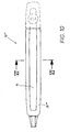
- in einer Fig. 2 entsprechenden Darstellung, ein drittes, nur einschalig ausgebildetes Ausführungsbeispiel der Erfindung, im Schnitt gemäß VI - VI aus Fig. 10,
- Fig. 7
- bei einer einschaligen Ausführungsform der Erfindung gemäß Fig. 6, eine Draufsicht auf den Griff und zwar in Blickrichtung des Pfeiles VII von Fig. 6,
- Fig. 8
- einen Schnitt gemäß VIII - VIII aus Fig. 7 mit der Projektion einer Rückansicht des vorderen Teils des Handgriffs,
- Fig. 9
- einen Schnitt gemäß IX - IX aus Fig. 8,
- Fig. 10
- eine Vorderansicht des dritten, nur einschalig ausgebildeten Ausführungsbeispiels der Erfindung.
- 10, 10'
- Handgriff
- 10"
- Alternative zu 10 (Fig. 3)
- 10'''
- Alternative zu 10 (Fig. 6)
- 11, 11'
- Griffende von 10 bzw. 10'
- 12
- Griffende
- 13, 13'
- Zylinderturm bei 10, 10'
- 14, 14'
- Hohlraum in 10 bzw. 10'
- 15, 15'
- Träger für 16 bzw. 16'
- 16, 16'
- elektronische Bauteile, Ferritstab
- 17, 17'
- Schauseite von 10 bzw. 10'
- 18, 18'
- Berührungsfuge zwischen 21, 22 bzw. 21', 22'
- 19, 19'
- Zierblende
- 20
- C-förmige Frontleiste an 10
- 20"
- Frontleiste für 10" (Fig. 3)
- 20'''
- Frontleiste für 10'' (Fig. 6)
- 21, 21', 21", 21'''
- U-Schale, U-förmige Grundschale
- 22, 22'
- Deckschale
- 23, 23'
- Schenkel von 21 bzw. 21'
- 23"
- Schenkel vpn 21 bei 10" (Fig. 3)
- 24, 24'
- Clipsverbindung zwischen 23, 22 bzw. 23', 22'
- 25
- Endabschnitte von 20
- 25''
- Endabschnitt von 20" (Fig. 3)
- 26
- stufenförmige Ausnehmung in 21, 22
- 27
- hakenartiges C-Ende von 20
- 27''
- Ende von 25''
- 28, 28'
- Unternut in 21, 21''
- 29
- Obernut in 22
- 29'
- Obernut in 21'
- 30
- Umriss von 10
- 31
- Schattenfuge bei 25
- 32
- Öffnung von 21 (Fig. 3)
- 32'
- Öffnung von 21" (Fig. 6)
- 33
- Aushöhlung von 25" (Fig. 3)
- 34
- Montagepfeil für 20'' (Fig. 3)
- 35
- Schnappverbindung von 36, 37
- 36
- Schnappelement von 35, Zahnaussparung
- 37
- Gegenschnappelement von 35, Zahnvorsprung
- 38
- Innenfläche von 25" (Fig. 3)
- 39
- Bodenbereich von 21
- 40
- stirnseitiges Schenkelende von 23" (Fig. 3)
- 41
- Auflaufschräge von 37
- 42
- steile Zahnflanke von 37
- 43
- Demontagepfeil von 20" (Fig. 3)
- 44
- Raum in 21 (Fig. 3)
- 44'
- Raum in 21 " (Fig. 6)
- 45
- Frontabschnitt von 20'''
- 46
- Vergussmasse
- 47
- Schenkel von 21" bei 10'''
- 48
- Basis von 21" bei 10'''
- 50
- Kabel
- 51
- Anschlussstecker
- 52
- Durchbruch
- 52', 52", 52'''
- Durchbrüche
Claims (12)
- Türaußengriff, insbesondere für Fahrzeuge, bestehend aus einem auf der Türaußenseite angeordneten bügelförmigen, wenigstens bereichsweise hohlen Handgriff (10", 10'''), der in seinem Hohlraum (44, 44') elektronische Bauteile (16) aufnimmt,
wobei der Handgriff (10"; 10''') wenigstens eine U-förmige Schale (21, 21''') aufweist, deren U-Raum (44, 44') zur Aufnahme der elektronischen Bauteile (16) dient und
im Verbindungsfall eine C-förmig profilierte Frontleiste (20"; 20''') die U-förmige Schale (21, 21''') schauseitig überspannt und an dieser verankert ist
die beiden C-Endabschnitte (25"; 25) der Frontleiste (20"; 20''') jeweils einen Umfangsbereich der U-förmigen Schale (21, 21''') über- bzw. untergreifen und dort verankert sind,
dadurch gekennzeichnet, dass
die elektronischen Bauteile (16) in einem nach oben geöffneten Träger wasserdicht vergossen sind. - Türaußengriff nach Anspruch 1, dadurch gekennzeichnet, dass die C-Frontleiste (20") mit ihrem einen C-Endabschnitt (25") die nach oben gerichtete U-Schalenöffnung (32) der Schale (21) unmittelbar abdeckt.
- Türaußengriff nach Anspruch 1, dadurch gekennzeichnet, dass die U-Öffnung (32') der U-förmigen Schale (21''') zum Frontabschnitt (45) der C-Frontleiste (20''') hin ausgerichtet ist und die Frontleiste (20''') mit ihrem Frontabschnitt (45) die U-Schalenöffnung (32') der Schale (21''') unmittelbar abdeckt.
- Türaußengriff nach Anspruch 2, dadurch gekennzeichnet, dass die beiden C-Endabschnitte (25") der C-Frontleiste (20") an ihrer Innenfläche (38) jeweils ein profiliertes Schnappelement, wie eine Zahnaussparung (36), aufweisen und dieses Schnappelement im Verbindungsfall mit einem Gegenschnappelement an der Schale (21), wie einem Zahnvorsprung (37), in Eingriff steht.
- Türaußengriff nach einem oder mehreren der Ansprüche 1 bis 4, dadurch gekennzeichnet, dass die C-Frontleiste (20", 20''') im wesentlichen parallel zueinander verlaufende C-Endabschnitte (25, 25") besitzt und die C-Endabschnitte (25, 25") zur Verbindung in einer seitlichen Schiebemontage (34) der C-Frontleiste (20", 20''') auf die Schale (21, 21''') aufschnappbar sind.
- Türaußengriff nach Anspruch 4 und 5, dadurch gekennzeichnet, dass das Schnapp- bzw. Gegenschnappelement (36, 37) ein Zahnprofil aufweist und dieses Zahnprofil auf seiner Aufschieberichtung (34) der C-Frontleiste (20") wirksamen Zahnflanke eine Auflaufschräge (41) für die C-Endabschnitte (25") besitzt, während in Gegenrichtung (43) eine steile Zahnflanke (42) vorgesehen ist.
- Türaußengriff nach Anspruch 1, dadurch gekennzeichnet, dass der Handgriff (10) eine zweiteilige (21, 22) Kombination aus einer U-förmigen Grundschale (21) und aus einer mit deren U-Schenkeln (23) verbundenen Deckschale (22) ist,
wobei zwischen den beiden Schalen (21, 22) im Verbindungsfall schauseitig eine Berührungsfuge (18) entsteht und der Hohlraum (14) zwischen den beiden Schalen (21, 22) zur Aufnahme der elektronischen Bauteile (16) dient,
die C-Endabschnitte (25) der C-Frontleiste (20) hakenartig abgewinkelte freie C-Enden (27) aufweisen
dadurch gekennzeichnet, dass
im Verbindungsfall die beiden Schalen (21,22) schauseitig von der Frontleiste (20) überspannt werden, wobei die beiden C-Endabschnitte (25) der Frontleiste (20) jeweils einen Umfangsbereich der Schalen (21, 22) übergreifen bzw. untergreifen und in einer Obernut (29) der Deckschale (22) bzw. in einer Unternut (28) der Grundschale (21) versenkt angeordnet sind. - Türaußengriff nach Anspruch 7, dadurch gekennzeichnet, dass die Grund- und die Deckschale (21, 22) im Bereich des Über- bzw. Untergriffs der Frontleiste (20) stufenförmig ausgenommen (26) sind und diese Ausnehmungen (26) an der Obernut (29) bzw. Unternut (28) enden.
- Türaußengriff nach einem der Ansprüche 1 bis 8, dadurch gekennzeichnet, dass im Montagefall die Frontleiste (20, 20", 20''') mit ihrem Umriss (30) bündig in die Schalen (21, 22) bzw. in die Schale (21, 21''') übergeht.
- Türaußengriff nach einem oder mehreren der Ansprüche 1 bis 9, dadurch gekennzeichnet, dass die Frontleiste (20; 20", 20''') ihrerseits schauseitig mit einer vorzugsweise eingelassenen Zierblende (19) versehen ist.
- Türaußengriff nach einem oder mehreren der Ansprüche 1 bis 10, dadurch gekennzeichnet, daß der Träger für die elektronischen Bauteile (16) ein nach fünf von sechs Seiten mit Wänden umgebener Container (15) ist, dessen Öffnung nach der Montage im Griff (10, 10'', 10''') nach oben weist.
- Türaußengriff nach Anspruch 11, dadurch gekennzeichnet, daß der Container (15) aus Hartkunststoff gefertigt ist.
Applications Claiming Priority (5)
| Application Number | Priority Date | Filing Date | Title |
|---|---|---|---|
| DE19935290A DE19935290B4 (de) | 1999-07-27 | 1999-07-27 | Türaußengriff, insbesondere für Fahrzeuge |
| DE19935290 | 1999-07-27 | ||
| DE29916091U DE29916091U1 (de) | 1999-07-27 | 1999-09-14 | Türaußengriff, insbesondere für Fahrzeuge |
| DE29916091U | 1999-09-14 | ||
| PCT/EP2000/006928 WO2001007736A1 (de) | 1999-07-27 | 2000-07-20 | Türaussengriff, insbesondere für fahrzeuge |
Publications (2)
| Publication Number | Publication Date |
|---|---|
| EP1212502A1 EP1212502A1 (de) | 2002-06-12 |
| EP1212502B1 true EP1212502B1 (de) | 2005-09-07 |
Family
ID=26054366
Family Applications (1)
| Application Number | Title | Priority Date | Filing Date |
|---|---|---|---|
| EP00945937A Expired - Lifetime EP1212502B1 (de) | 1999-07-27 | 2000-07-20 | Türaussengriff, insbesondere für fahrzeuge |
Country Status (9)
| Country | Link |
|---|---|
| US (1) | US6769154B1 (de) |
| EP (1) | EP1212502B1 (de) |
| JP (1) | JP3695531B2 (de) |
| CN (1) | CN1295419C (de) |
| AT (1) | ATE304105T1 (de) |
| AU (1) | AU5986100A (de) |
| DE (1) | DE50011128D1 (de) |
| ES (1) | ES2244453T3 (de) |
| WO (1) | WO2001007736A1 (de) |
Cited By (1)
| Publication number | Priority date | Publication date | Assignee | Title |
|---|---|---|---|---|
| WO2009152801A1 (de) * | 2008-06-19 | 2009-12-23 | Huf Hülsbeck & Fürst Gmbh & Co. Kg | Türaussengriff |
Families Citing this family (28)
| Publication number | Priority date | Publication date | Assignee | Title |
|---|---|---|---|---|
| DE19961360A1 (de) * | 1999-12-17 | 2001-07-05 | Bosch Gmbh Robert | Türaußengriffanordnung für eine Kraftfahrzeugtür |
| EP1291480A1 (de) * | 2001-08-16 | 2003-03-12 | Valeo Sicurezza Abitacolo S.p.A. | Aussengriff für ein Kraftfahrzeug |
| ES2305163T3 (es) * | 2001-08-16 | 2008-11-01 | Valeo Sicurezza Abitacolo S.P.A. | Manija de abertura que incorpora un modulo electronico, en especial para vehiculo automovil. |
| AU2002361052A1 (en) * | 2001-12-12 | 2003-06-23 | Witte-Velbert Gmbh And Co. Kg | Handle, in particular designed for motor vehicle doors |
| EP1513999A1 (de) * | 2002-06-20 | 2005-03-16 | Schaffner Emv Ag | Elektronische steuerschaltung mit einem sender f r ein fahrz eugt r-schliesssystem |
| US6965352B2 (en) * | 2003-04-08 | 2005-11-15 | Matsushita Electric Industrial Co., Ltd. | Antenna device for vehicles and vehicle antenna system and communication system using the antenna device |
| JP4342207B2 (ja) | 2003-04-22 | 2009-10-14 | アイシン精機株式会社 | 車両用ドアハンドル装置 |
| GB2421799B (en) * | 2003-06-20 | 2006-11-15 | Honda Lock Kk | Vehicle door outer handle system |
| JP3696866B2 (ja) * | 2003-10-20 | 2005-09-21 | 株式会社アルファ | ドア開閉装置 |
| JP4154309B2 (ja) * | 2003-10-21 | 2008-09-24 | 株式会社ホンダロック | 車両用ドアハンドル装置 |
| JP2005136689A (ja) * | 2003-10-30 | 2005-05-26 | Alpha Corp | アンテナ |
| JP4160488B2 (ja) * | 2003-10-30 | 2008-10-01 | 株式会社アルファ | アンテナ |
| EP1582659B1 (de) * | 2004-03-29 | 2013-03-20 | Aisin Seiki Kabushiki Kaisha | Türgriff für einen Fahrzeug |
| DE602005021841D1 (de) | 2004-03-30 | 2010-07-29 | Honda Lock Kk | Türgriffanordnung für eine Kraftfahrzeugtür |
| JP4443307B2 (ja) * | 2004-05-31 | 2010-03-31 | 株式会社アルファ | ドアハンドル装置 |
| DE102004038569B3 (de) * | 2004-08-06 | 2005-10-20 | Huf Huelsbeck & Fuerst Gmbh | Kraftfahrzeugtürgriff |
| US7201415B2 (en) * | 2004-12-14 | 2007-04-10 | Putco, Inc. | Method and apparatus for applying a decorative design to a door handle |
| DE102005004572A1 (de) * | 2005-02-01 | 2006-08-17 | Bayerische Motoren Werke Ag | Türgriff, insbesondere für eine Kraftfahrzeugtür |
| JP4882370B2 (ja) * | 2005-12-27 | 2012-02-22 | アイシン精機株式会社 | 車両用ドアハンドル |
| DE102007011080A1 (de) * | 2007-03-07 | 2008-09-11 | Huf Hülsbeck & Fürst Gmbh & Co. Kg | Außengriff an Türen oder Klappen von Fahrzeugen |
| WO2008137634A1 (en) | 2007-05-03 | 2008-11-13 | Donnelly Corporation | Illumination module for a vehicle |
| JP4751860B2 (ja) * | 2007-07-27 | 2011-08-17 | アイシン精機株式会社 | ドアハンドル装置 |
| JP5374173B2 (ja) * | 2009-01-30 | 2013-12-25 | 株式会社アルファ | 車両用ドアハンドル装置 |
| US8037577B2 (en) * | 2009-03-16 | 2011-10-18 | Infar Industrial Co., Ltd. | Tool handle |
| TWI458420B (zh) * | 2011-03-14 | 2014-10-21 | Wistron Corp | 易於拆裝之門蓋結構 |
| JP5580263B2 (ja) | 2011-08-23 | 2014-08-27 | 株式会社ホンダロック | 車両用ドアのアウトハンドル装置 |
| US20140292004A1 (en) * | 2013-04-01 | 2014-10-02 | Magna Mirrors Of America, Inc. | Vehicle door handle system |
| CN219061285U (zh) * | 2022-09-09 | 2023-05-23 | 伊利诺斯工具制品有限公司 | 用于车辆的门把手组件 |
Family Cites Families (9)
| Publication number | Priority date | Publication date | Assignee | Title |
|---|---|---|---|---|
| DE1974519U (de) * | 1967-05-22 | 1967-12-07 | Biedermann K G Geb | Vorrichtung zum abschneiden und aufschweissen von schuhoesenstreifen auf schuhschaftteile. |
| JP2921640B2 (ja) * | 1994-03-17 | 1999-07-19 | 矢崎総業株式会社 | 給電コネクタ |
| DE19745149C2 (de) * | 1996-04-27 | 2002-10-31 | Huf Huelsbeck & Fuerst Gmbh | Schließsystem, insbesondere für Kraftfahrzeuge |
| DE19633894C2 (de) * | 1996-08-22 | 1999-12-23 | Huf Huelsbeck & Fuerst Gmbh | Vorrichtung zur Betätigung eines in einer Tür, einer Klappe o. dgl. eingebauten Schlosses, insbesondere bei einem Fahrzeug |
| JPH10297571A (ja) * | 1997-04-23 | 1998-11-10 | Masuyuki Naruse | ハンドルグリップ機構 |
| AU9143698A (en) * | 1997-12-03 | 1999-06-24 | Robert Bosch Gmbh | A door handle assembly |
| US6007356A (en) * | 1998-07-02 | 1999-12-28 | Stein; Myron | Water tight quick connect electrical connector |
| FR2819538B1 (fr) * | 2001-01-12 | 2003-10-17 | Mecaplast Sa | Poignee de portiere de vehicule automobile |
| JP3566943B2 (ja) * | 2001-07-02 | 2004-09-15 | アイシン精機株式会社 | 車両用ドアハンドル |
-
2000
- 2000-07-20 ES ES00945937T patent/ES2244453T3/es not_active Expired - Lifetime
- 2000-07-20 WO PCT/EP2000/006928 patent/WO2001007736A1/de not_active Ceased
- 2000-07-20 CN CNB008108862A patent/CN1295419C/zh not_active Expired - Fee Related
- 2000-07-20 US US10/031,770 patent/US6769154B1/en not_active Expired - Lifetime
- 2000-07-20 AT AT00945937T patent/ATE304105T1/de not_active IP Right Cessation
- 2000-07-20 JP JP2001512143A patent/JP3695531B2/ja not_active Expired - Fee Related
- 2000-07-20 AU AU59861/00A patent/AU5986100A/en not_active Abandoned
- 2000-07-20 EP EP00945937A patent/EP1212502B1/de not_active Expired - Lifetime
- 2000-07-20 DE DE50011128T patent/DE50011128D1/de not_active Expired - Lifetime
Cited By (2)
| Publication number | Priority date | Publication date | Assignee | Title |
|---|---|---|---|---|
| WO2009152801A1 (de) * | 2008-06-19 | 2009-12-23 | Huf Hülsbeck & Fürst Gmbh & Co. Kg | Türaussengriff |
| DE102008036512A1 (de) * | 2008-06-19 | 2009-12-24 | Huf Hülsbeck & Fürst Gmbh & Co. Kg | Türaußengriff |
Also Published As
| Publication number | Publication date |
|---|---|
| CN1295419C (zh) | 2007-01-17 |
| EP1212502A1 (de) | 2002-06-12 |
| JP2003505626A (ja) | 2003-02-12 |
| DE50011128D1 (de) | 2005-10-13 |
| CN1365417A (zh) | 2002-08-21 |
| AU5986100A (en) | 2001-02-13 |
| JP3695531B2 (ja) | 2005-09-14 |
| ATE304105T1 (de) | 2005-09-15 |
| WO2001007736A1 (de) | 2001-02-01 |
| ES2244453T3 (es) | 2005-12-16 |
| US6769154B1 (en) | 2004-08-03 |
Similar Documents
| Publication | Publication Date | Title |
|---|---|---|
| EP1212502A1 (de) | Türaussengriff, insbesondere für fahrzeuge | |
| DE3440899C1 (de) | Schaltschrank mit einem boxartigen Schrankkorpus und mit einer die OEffnung desselben verschliessenden Schranktuer | |
| DE19803402A1 (de) | Anordnung zur Befestigung eines Formteils an einem Karosseriekörper | |
| DE19737667C1 (de) | Reihe von aneinandergereihten Schaltschränken | |
| DE102007011080A1 (de) | Außengriff an Türen oder Klappen von Fahrzeugen | |
| DE19935290B4 (de) | Türaußengriff, insbesondere für Fahrzeuge | |
| DE19755150A1 (de) | Stangenausrichtungsaufnahme für ein Türmodul | |
| DE19843422B4 (de) | Türschloss eines Kraftfahrzeugs | |
| DE60133217T2 (de) | Halteclip zum Anbringen von Komponenten an einer Seitenzierleiste | |
| DE102016123889A1 (de) | Verbindungsanordnung zum Verbinden eines Pfostens mit einem Rahmenprofil eines Fensters oder einer Türe aus Kunststoff | |
| DE60011949T2 (de) | Verriegelungsbeschlag vom Typ Treibstangenbeschlag oder dergleichen | |
| EP1635434A1 (de) | Elektrische/elektronische Installationseinheit | |
| DE69103083T2 (de) | Griffeinheit für ein Fahrzeug und diesbezügliches Verfahren des Zusammenbaues. | |
| DE10031111B4 (de) | Stoßleiste für ein Fahrzeug | |
| EP1134334B1 (de) | Schliessbügel mit einer Eingriffsöffnung für ein Sperrglied eines Schlosses | |
| DE3741830C2 (de) | ||
| DE3605604A1 (de) | Einteilige klammer | |
| EP1515867A1 (de) | Befestigungsvorrichtung für einen handgriff | |
| DE1659705A1 (de) | Aus Kunststoffbauteilen zusammensetzbare wasserdichte Aussenfensterbank | |
| DE10342664A1 (de) | Elektronischer Schlüssel | |
| DE3601891A1 (de) | Rastvorrichtung zur befestigung eines anbauteiles, verfahren zur montage einer mit einem anbauteil versehenen wandverkleidung sowie kraftfahrzeugtuer mit einem als tuertasche ausgebildeten anbauteil | |
| DE60036151T2 (de) | Abschlussvorrichtung für eine Karosserieöffnung, mit Dichtungs- und/oder Versteifungselement, und korrespondierendes Herstellungsverfahren | |
| DE60309374T2 (de) | Türgriff, insbesondere für Fahrzeuge | |
| DE102019116824A1 (de) | Dichtungsanordnung für ein Fahrzeugfenster, Fahrzeugtür und Kraftfahrzeug | |
| DE68907970T2 (de) | Konstruktion zum Tragen eines grossen Spiegels und ein grosser Spiegel, der diese Konstruktion hat. |
Legal Events
| Date | Code | Title | Description |
|---|---|---|---|
| PUAI | Public reference made under article 153(3) epc to a published international application that has entered the european phase |
Free format text: ORIGINAL CODE: 0009012 |
|
| 17P | Request for examination filed |
Effective date: 20020117 |
|
| AK | Designated contracting states |
Kind code of ref document: A1 Designated state(s): AT BE CH CY DE DK ES FI FR GB GR IE IT LI LU MC NL PT SE |
|
| R17P | Request for examination filed (corrected) |
Effective date: 20020117 |
|
| 17Q | First examination report despatched |
Effective date: 20041115 |
|
| GRAP | Despatch of communication of intention to grant a patent |
Free format text: ORIGINAL CODE: EPIDOSNIGR1 |
|
| GRAS | Grant fee paid |
Free format text: ORIGINAL CODE: EPIDOSNIGR3 |
|
| GRAA | (expected) grant |
Free format text: ORIGINAL CODE: 0009210 |
|
| AK | Designated contracting states |
Kind code of ref document: B1 Designated state(s): AT BE CH CY DE DK ES FI FR GB GR IE IT LI LU MC NL PT SE |
|
| PG25 | Lapsed in a contracting state [announced via postgrant information from national office to epo] |
Ref country code: NL Free format text: LAPSE BECAUSE OF FAILURE TO SUBMIT A TRANSLATION OF THE DESCRIPTION OR TO PAY THE FEE WITHIN THE PRESCRIBED TIME-LIMIT Effective date: 20050907 Ref country code: FI Free format text: LAPSE BECAUSE OF FAILURE TO SUBMIT A TRANSLATION OF THE DESCRIPTION OR TO PAY THE FEE WITHIN THE PRESCRIBED TIME-LIMIT Effective date: 20050907 Ref country code: IE Free format text: LAPSE BECAUSE OF FAILURE TO SUBMIT A TRANSLATION OF THE DESCRIPTION OR TO PAY THE FEE WITHIN THE PRESCRIBED TIME-LIMIT Effective date: 20050907 Ref country code: GB Free format text: LAPSE BECAUSE OF FAILURE TO SUBMIT A TRANSLATION OF THE DESCRIPTION OR TO PAY THE FEE WITHIN THE PRESCRIBED TIME-LIMIT Effective date: 20050907 |
|
| REG | Reference to a national code |
Ref country code: GB Ref legal event code: FG4D Free format text: NOT ENGLISH |
|
| REG | Reference to a national code |
Ref country code: CH Ref legal event code: EP |
|
| REG | Reference to a national code |
Ref country code: IE Ref legal event code: FG4D Free format text: LANGUAGE OF EP DOCUMENT: GERMAN |
|
| REF | Corresponds to: |
Ref document number: 50011128 Country of ref document: DE Date of ref document: 20051013 Kind code of ref document: P |
|
| PG25 | Lapsed in a contracting state [announced via postgrant information from national office to epo] |
Ref country code: SE Free format text: LAPSE BECAUSE OF FAILURE TO SUBMIT A TRANSLATION OF THE DESCRIPTION OR TO PAY THE FEE WITHIN THE PRESCRIBED TIME-LIMIT Effective date: 20051207 Ref country code: DK Free format text: LAPSE BECAUSE OF FAILURE TO SUBMIT A TRANSLATION OF THE DESCRIPTION OR TO PAY THE FEE WITHIN THE PRESCRIBED TIME-LIMIT Effective date: 20051207 Ref country code: GR Free format text: LAPSE BECAUSE OF FAILURE TO SUBMIT A TRANSLATION OF THE DESCRIPTION OR TO PAY THE FEE WITHIN THE PRESCRIBED TIME-LIMIT Effective date: 20051207 |
|
| REG | Reference to a national code |
Ref country code: ES Ref legal event code: FG2A Ref document number: 2244453 Country of ref document: ES Kind code of ref document: T3 |
|
| PG25 | Lapsed in a contracting state [announced via postgrant information from national office to epo] |
Ref country code: PT Free format text: LAPSE BECAUSE OF FAILURE TO SUBMIT A TRANSLATION OF THE DESCRIPTION OR TO PAY THE FEE WITHIN THE PRESCRIBED TIME-LIMIT Effective date: 20060207 |
|
| NLV1 | Nl: lapsed or annulled due to failure to fulfill the requirements of art. 29p and 29m of the patents act | ||
| GBV | Gb: ep patent (uk) treated as always having been void in accordance with gb section 77(7)/1977 [no translation filed] |
Effective date: 20050907 |
|
| ET | Fr: translation filed | ||
| REG | Reference to a national code |
Ref country code: IE Ref legal event code: FD4D |
|
| PLBE | No opposition filed within time limit |
Free format text: ORIGINAL CODE: 0009261 |
|
| STAA | Information on the status of an ep patent application or granted ep patent |
Free format text: STATUS: NO OPPOSITION FILED WITHIN TIME LIMIT |
|
| PG25 | Lapsed in a contracting state [announced via postgrant information from national office to epo] |
Ref country code: MC Free format text: LAPSE BECAUSE OF NON-PAYMENT OF DUE FEES Effective date: 20060731 Ref country code: CH Free format text: LAPSE BECAUSE OF NON-PAYMENT OF DUE FEES Effective date: 20060731 Ref country code: BE Free format text: LAPSE BECAUSE OF NON-PAYMENT OF DUE FEES Effective date: 20060731 Ref country code: LI Free format text: LAPSE BECAUSE OF NON-PAYMENT OF DUE FEES Effective date: 20060731 |
|
| 26N | No opposition filed |
Effective date: 20060608 |
|
| REG | Reference to a national code |
Ref country code: CH Ref legal event code: PL |
|
| PG25 | Lapsed in a contracting state [announced via postgrant information from national office to epo] |
Ref country code: AT Free format text: LAPSE BECAUSE OF NON-PAYMENT OF DUE FEES Effective date: 20060720 |
|
| BERE | Be: lapsed |
Owner name: HUF HULSBECK & FURST G.M.B.H. & CO. KG Effective date: 20060731 |
|
| PG25 | Lapsed in a contracting state [announced via postgrant information from national office to epo] |
Ref country code: LU Free format text: LAPSE BECAUSE OF NON-PAYMENT OF DUE FEES Effective date: 20060720 |
|
| PG25 | Lapsed in a contracting state [announced via postgrant information from national office to epo] |
Ref country code: CY Free format text: LAPSE BECAUSE OF FAILURE TO SUBMIT A TRANSLATION OF THE DESCRIPTION OR TO PAY THE FEE WITHIN THE PRESCRIBED TIME-LIMIT Effective date: 20050907 |
|
| REG | Reference to a national code |
Ref country code: FR Ref legal event code: PLFP Year of fee payment: 16 |
|
| REG | Reference to a national code |
Ref country code: FR Ref legal event code: PLFP Year of fee payment: 17 |
|
| REG | Reference to a national code |
Ref country code: FR Ref legal event code: PLFP Year of fee payment: 18 |
|
| REG | Reference to a national code |
Ref country code: DE Ref legal event code: R084 Ref document number: 50011128 Country of ref document: DE |
|
| REG | Reference to a national code |
Ref country code: FR Ref legal event code: PLFP Year of fee payment: 19 |
|
| PGFP | Annual fee paid to national office [announced via postgrant information from national office to epo] |
Ref country code: IT Payment date: 20180720 Year of fee payment: 19 Ref country code: FR Payment date: 20180724 Year of fee payment: 19 Ref country code: ES Payment date: 20180816 Year of fee payment: 19 |
|
| PGFP | Annual fee paid to national office [announced via postgrant information from national office to epo] |
Ref country code: DE Payment date: 20190627 Year of fee payment: 20 |
|
| PG25 | Lapsed in a contracting state [announced via postgrant information from national office to epo] |
Ref country code: FR Free format text: LAPSE BECAUSE OF NON-PAYMENT OF DUE FEES Effective date: 20190731 |
|
| REG | Reference to a national code |
Ref country code: DE Ref legal event code: R071 Ref document number: 50011128 Country of ref document: DE |
|
| PG25 | Lapsed in a contracting state [announced via postgrant information from national office to epo] |
Ref country code: IT Free format text: LAPSE BECAUSE OF NON-PAYMENT OF DUE FEES Effective date: 20190720 |
|
| REG | Reference to a national code |
Ref country code: ES Ref legal event code: FD2A Effective date: 20201130 |
|
| PG25 | Lapsed in a contracting state [announced via postgrant information from national office to epo] |
Ref country code: ES Free format text: LAPSE BECAUSE OF NON-PAYMENT OF DUE FEES Effective date: 20190721 |