EP1212773B1 - Schutzschalter mit leicht zu montierender auswechselbarer auslöseeinheit - Google Patents
Schutzschalter mit leicht zu montierender auswechselbarer auslöseeinheit Download PDFInfo
- Publication number
- EP1212773B1 EP1212773B1 EP00949842A EP00949842A EP1212773B1 EP 1212773 B1 EP1212773 B1 EP 1212773B1 EP 00949842 A EP00949842 A EP 00949842A EP 00949842 A EP00949842 A EP 00949842A EP 1212773 B1 EP1212773 B1 EP 1212773B1
- Authority
- EP
- European Patent Office
- Prior art keywords
- trip unit
- conductor means
- nut
- circuit breaker
- housing
- Prior art date
- Legal status (The legal status is an assumption and is not a legal conclusion. Google has not performed a legal analysis and makes no representation as to the accuracy of the status listed.)
- Expired - Lifetime
Links
- 239000004020 conductor Substances 0.000 claims description 36
- 230000007246 mechanism Effects 0.000 claims description 22
- 230000009471 action Effects 0.000 description 8
- 239000002184 metal Substances 0.000 description 4
- 238000010276 construction Methods 0.000 description 3
- 238000004519 manufacturing process Methods 0.000 description 3
- 238000000034 method Methods 0.000 description 3
- 230000008569 process Effects 0.000 description 3
- 230000004044 response Effects 0.000 description 2
- 230000003467 diminishing effect Effects 0.000 description 1
- 238000010891 electric arc Methods 0.000 description 1
- 230000004907 flux Effects 0.000 description 1
- 230000000977 initiatory effect Effects 0.000 description 1
- 238000013021 overheating Methods 0.000 description 1
Images


Classifications
-
- H—ELECTRICITY
- H01—ELECTRIC ELEMENTS
- H01H—ELECTRIC SWITCHES; RELAYS; SELECTORS; EMERGENCY PROTECTIVE DEVICES
- H01H71/00—Details of the protective switches or relays covered by groups H01H73/00 - H01H83/00
- H01H71/08—Terminals; Connections
-
- H—ELECTRICITY
- H01—ELECTRIC ELEMENTS
- H01H—ELECTRIC SWITCHES; RELAYS; SELECTORS; EMERGENCY PROTECTIVE DEVICES
- H01H71/00—Details of the protective switches or relays covered by groups H01H73/00 - H01H83/00
- H01H71/02—Housings; Casings; Bases; Mountings
- H01H71/0207—Mounting or assembling the different parts of the circuit breaker
- H01H71/0228—Mounting or assembling the different parts of the circuit breaker having provisions for interchangeable or replaceable parts
-
- H—ELECTRICITY
- H01—ELECTRIC ELEMENTS
- H01H—ELECTRIC SWITCHES; RELAYS; SELECTORS; EMERGENCY PROTECTIVE DEVICES
- H01H71/00—Details of the protective switches or relays covered by groups H01H73/00 - H01H83/00
- H01H71/10—Operating or release mechanisms
- H01H71/12—Automatic release mechanisms with or without manual release
- H01H71/14—Electrothermal mechanisms
-
- H—ELECTRICITY
- H01—ELECTRIC ELEMENTS
- H01H—ELECTRIC SWITCHES; RELAYS; SELECTORS; EMERGENCY PROTECTIVE DEVICES
- H01H71/00—Details of the protective switches or relays covered by groups H01H73/00 - H01H83/00
- H01H71/10—Operating or release mechanisms
- H01H71/12—Automatic release mechanisms with or without manual release
- H01H71/24—Electromagnetic mechanisms
-
- H—ELECTRICITY
- H01—ELECTRIC ELEMENTS
- H01H—ELECTRIC SWITCHES; RELAYS; SELECTORS; EMERGENCY PROTECTIVE DEVICES
- H01H71/00—Details of the protective switches or relays covered by groups H01H73/00 - H01H83/00
- H01H71/74—Means for adjusting the conditions under which the device will function to provide protection
- H01H71/7409—Interchangeable elements
-
- H—ELECTRICITY
- H01—ELECTRIC ELEMENTS
- H01H—ELECTRIC SWITCHES; RELAYS; SELECTORS; EMERGENCY PROTECTIVE DEVICES
- H01H71/00—Details of the protective switches or relays covered by groups H01H73/00 - H01H83/00
- H01H71/74—Means for adjusting the conditions under which the device will function to provide protection
- H01H71/7418—Adjusting both electrothermal and electromagnetic mechanism
Definitions
- the subject matter of this invention is related generally to molded case circuit breakers and more specifically to removable trip units for molded case circuit breakers.
- Molded case circuit breakers are well known in the art as exemplified by U.S. Patent 5,910,760 issued June 8, 1999 to Malingowski et al., entitled “Circuit Breaker with Double Rate Spring” and assigned to the assignee of the present application. The foregoing is incorporated herein by reference.
- Molded case circuit breakers include a set of separable main contacts, one of which is usually fixed and one of which is movable for automatically opening upon the occurrence of an overload or short circuit electrical current in the network which the circuit breaker is provide to protect.
- the separable main contacts are opened as a result of the functioning of a latched operating mechanism, which is interconnectable by way of an operating handle to a region outside of the circuit breaker.
- the operating handle may be used to trip the circuit breaker manually or to reset and close the circuit breaker contacts once they have been opened automatically.
- the reset action is required because circuit breakers must be mechanically charged to be in a state to reopen immediately upon closure in the event that the fault which cause the tripping in the first place has not disappeared.
- Molded case circuit breakers have trip units, which are often removably insertable in the circuit breaker case.
- the trip unit in addition has at least two calibratabic functions, one of which is generally identified as thermal tripping and the other of which is generally identified as magnetic tripping.
- the trip unit includes a rotatable trip bar, which when rotated will actuate a latchable tripping operation within the operating mechanism to automatically open the circuit breaker contacts.
- the rotatable trip bar is usually actuated in one of two ways. The first way is in response to what is called a magnetic tripping of the circuit breaker.
- a bi-metal element is heated by a heater element which conducts the electrical current flowing through the separable main contacts.
- a heater element which conducts the electrical current flowing through the separable main contacts.
- the bi-metal element flexes or moves it impinges upon the tripping bar causing it to flex and move correspondingly, until eventually a point is reached in which the tripping bar causes the circuit breaker to unlatch and trip automatically.
- Both the magnetic trip mechanism and the thermal trip mechanism usually require initial calibration.
- the electrical current flows through the circuit interrupter from the load by way of a terminal collar to the load terminal of the circuit breaker and from there into the trip unit where it flows through the previously mentioned heater which in turn is serially connected to the electron magnetic member of the magnetic trip device. From there it is interconnected by way of a flexible cable to one end of a moveable contact arm and from there to the main contact on the moveable contact arm.
- the contact arm When the contact arm is closed, it is closed upon a fixed contact which is supported usually on u-shaped conductor, which in turn is interconnected with a line terminal and there to the line terminal collar and finally to the electrical line.
- the circuit breaker usually has an arc chute for assisting in diminishing the electrical arc drawn between the separating contacts during the opening operation for extinguishing of the arc.
- the circuit breaker also has a slot motor arrangement, which is utilized to interact magnetically with the electrical current flowing in the opening contact arm to accelerate the opening of the contact arm magnetically.
- the operating mechanism usually consists of a series of levers and linkages, which are interconnected with the separable main moveable contact arm, the handle mechanism, and by way of a latch arrangement with the aforementioned trip bar. Description and operation of all of the above may be found in the previous mentioned, incorporated by reference '760 patent.
- each circuit breaker usually contains a trip unit which is integrated into the circuit breaker case during the construction process and which causes the tripping of a circuit breaker due to either a magnetic level current overload or a thermal level current overload.
- a trip unit may be found in the aforementioned U.S. Patent 5,901,760.
- Utilization of a trip unit of this kind usually requires mounting of the trip unit from the front or faceplate side thereof. That requires that the area above the mounting screws for the circuit breaker be left open to allow access for a driver which often results in wasted space in the circuit breaker. It would be advantageous if a trip unit could be found in which this wasted space is no longer required and which could be placed into the circuit breaker very late in the manufacturing process, even after the main circuit breaker frame had been completed.
- EP 0 076 719 A1 which is directed to a disconnectable connection between a trip unit and a circuit breaker.
- the disconnectable connections between the removable trip unit and the circuit breaker unit include inclined connection lugs so as to provide access to the set-screws of the connections on the narrow side face of the circuit breaker casing.
- circuit interrupter device as set forth in claim 1 is provided.
- Preferred embodiments are disclosed in the dependant claims.
- circuit interrupter device having a housing.
- an operating mechanism means disposed within the housing.
- separable contacts are disposed within the housing in cooperation with the operating mechanism for being opened by the operating mechanism
- a trip unit is disposed within the housing in cooperation with the operating mechanism for actuating the operating mechanism for opening the separable contacts
- the trip unit has an internal trip unit conductor with an external terminal, the external terminal is connectable in a region outside of the housing with an external conductor, a frame conductor is disposed electrically between the separable contacts and the internal trip unit conductor, there is also a bolt for joining the internal trip unit conductor and the frame conductor, the bolt is accessible from said region outside of the housing.
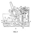
- a molded case circuit breaker or interrupter 10 having a main base 12 and primary cover 14. Attached to the primary cover 14 is a secondary cover 16. A handle 18 extends through a secondary escutcheon 22A in the secondary cover 16 and aligned primary escutcheon 22B in the primary cover 14. An operating mechanism 20 is interconnected with the handle 18 for opening and closing separable main contacts in a manner which will be described hereinafter.
- This circuit breaker has a line end 15 and load end 17.
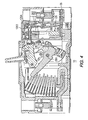
- the circuit breaker or interrupter includes a removable trip unit 24. Removable trip unit 24 has an underlapping lip 24X, the purpose of which will be described hereinafter. There are also depicted a load terminal 26, a right side accessory region or pocket 27 and a left side accessory pocket or region 31.
- Line terminal 36 is disposed to the left in Figure 2, for example, at the line end 15 of the circuit interrupter in a terminal cave or pocket 29.
- a load terminal 26 is disposed to the right in Figure 2, for example, in a load terminal cave or pocket 29.
- a line terminal collar 38 which will be described in more detail hereinafter, and to the right is provided a load terminal jumper-to-movable contact arm conductor 802.
- a flexible conductor 39 Connected to conductor 802 is a flexible conductor 39, which is interconnected with movable contact arm 32 as shown schematically.
- the load terminal jumper or frame conductor 802 is interconnected at its other end with a bi-metal heater 180, which in turn is interconnected at its other end with the terminal 26. Consequently, when the circuit interrupter separable main contacts 28 and 30 are closed upon each other, there is a complete circuit through the circuit interrupter from right to left starting with line conductor 26 through bi-metal heater 180, through load terminal jumper or frame conductor 802, through flexible conductor 39, through the movable contact arm 32, through contact 28 to contact 30 and from there through the fixed contact support or u-shaped member 34 to line terminal 36.
- the operating mechanism includes a cradle 52, which is pivoted on one end at a cradle fixed pivoted pin 54 by way of an opening 54A in the cradle for placement of the cradle fixed pivoted pin therein.
- the cradle includes a cradle-to-side accessory region side protrusion 55.
- an upper toggle link 46 and a lower toggle link 48 are joined pivotally by an upper and lower toggle link pin 50.
- There is provided a lower toggle link to movable contact arm main pivot assemble attachment pin 56 which is affixed to the movable contact arm 32 at an opening 56A.
- a cradle to upper toggle link pivot pin 58 by which the upper toggle link 46 is placed in physical contact with the cradle 52.
- a movable contact arm main pivot assembly 59 which movably, rotatably pivots on a pivot 60.
- a primary frame latch 62 which operates or rotates on a primary frame latch pivot 64.
- the primary frame latch 62 cooperates with a secondary frame latch 68, which rotates on a secondary frame latch pivot 70.
- the operating power for the tripping operating of the circuit breaker is provided by a charged main toggle coil spring 72.
- the main toggle coil spring is interconnected with a handle yoke 44 by way of a handle yoke attachment post 45.
- Cradle 52 has a cradle lip 73, which is captured or held in place by the primary latch 62 when the separable main contacts 28 and 30 are closed. No tripping of the circuit breaker can take place by way of the operating mechanism until the aforementioned primary frame latch 62 has been actuated away from the cradle lip 73 in a manner which will be described hereinafter.
- a combination secondary-frame-latch-primary-frame-latch torsion spring 78 which exerts force against both latches sufficient to cause appropriate movement thereof at the appropriate time.
- the secondary frame latch has a laterally extending trip protrusion 79, the purpose of which will be described later hereinafter.
- Actuation of the primary and secondary frame latches occurs exclusively by way of the utilization of a resetable trip unit trip plunger 74, which is contained entirely within the removable trip unit 24.
- the trip unit trip plunger 74 is controlled or latched by way of a plunger latch or interference latch 75.
- the secondary frame latch 68 is in disposition to be struck by the moving trip unit plunger abutment surface 288. Upon opening of the separable main contacts 30 and 28, an electric arc is drawn therebetween which is exposed to an arc chute 77.
- the secondary frame latch 68 has a bottom portion 89, upon which is disposed an arcuate stop surface 90 for the primary frame latch 62. There is also provided above that arcuate stop surface and as part of the acruate stop member a latch surface 92.
- the operating mechanism described herein may be the same as found in U.S. Patent 5,910,760 issued June 8, 1999 to Malingowski et al., entitled "Circuit Breaker with Double Rate Spring". Thought the primary and secondary frame latches are disposed within the case 12, the trip unit plunger 75 is responsible for initiating all tripping action from the trip unit 24 into the region of the secondary latch 68. Alternatively, the secondary latch 68 may be actuated by a push-to-trip button in a manner, which will be described hereinafter. The secondary latch 68 is actuated to rotate to the left as shown in Figures 2, 3 and 4, for example, in direction 81 about its pivot 70.
- the acruate stop surface 90 for the secondary frame latch 68 rotates away from the bottom of the primary frame latch 62 until the lateral latch surface 92 rotates into a disposition to allow the bottom of the primary frame latch 62 to rotate to the right under the force of the cradle 72.
- Patent 5,910,760 The important part of the operation with respect to this feature is the movement of the secondary frame latch point 76 in the direction opposite to direction 82, against the plunger face 288 in a manner, which will be described later hereinafter. However, if movement of the plunger face 288 in the rightward direction against its plunger spring, as will be described hereinafter, is prevented because of the latching of the plunger member 74, in a manner which will be described hereinafter, then the circuit breaker can not be reset.
- An important feature of the invention lies in the fact that the ultimate control of the resetting of the circuit breaker and tripping of the circuit breaker can be accomplished only from the removable trip unit 24, rather than from the operating mechanism 20.
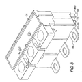
- a pre-attachment nut casing 800 is disposed in the back wall of the back portion 104 of the trip unit 24.
- a load terminal jumper or frame conductor 802 which interconnects the heater 180 with the movable contact arm 32 via a flexible conductor 39 which joins the back part of the arm 32 in the region of the rotating assembly 59.
- the vertical portion 803 of the load terminal jumper 802 is best seen in Figure 7 as being bifurcated and having a pair of tines 803A which are deposed around a u-shaped opening 810.
- Member 802 may be moved upwardly into the casing 800 to align the nut 164 with the pre-existing hole 811 in the back portion of the member 180 and with the fastening bolt 182.
- the fastening bolt 182 may be driven in the direction 804 through the u-shaped opening 810 into the pre-disposed nut 164 and hole or opening 811 in the back member of the heater 180 for complete fastening thereof.
- the u-shaped opening and the tines may be inserted into the path 804 of the bolt 182 from the direction 812 to reduce manufacturing compilation even more. This eliminates the requirement for fastening the arrangement within the circuit breaker itself during the initial construction process, which is a feature of the present invention. Since the trip u nit represents the entire load end of the circuit breaker such a construction process is possible, which greatly reduces manufacturing compilation and time.
Landscapes
- Breakers (AREA)
Claims (6)
- Eine Schalterunterbrechungsvorrichtung (10), die Folgendes aufweist:wobei der Betätigungsmechanismus (20) mit den erwähnten trennbaren Kontaktmitteln (28, 30, 32, 34) gekuppelt ist;ein Gehäuse (12, 14, 16);Betätigungsmechanismusmittel (20) angeordnet innerhalb des Gehäuses;trennbare Kontaktmittel (28, 30, 32, 34) angeordnet innerhalb des Gehäuses mit zwei Kontakten (28, 30), die zum Öffnen strukturiert sind;
wobei der Betätigungsmechanismus (20) derart strukturiert ist, dass er die trennbaren Kontaktmittel (28, 30, 32, 34) öffnet;
Auslöseeinheitmittel (24) angeordnet benachbart zum Gehäuse (12, 14, 16) und gekuppelt mit den Betriebsmechanismusmitteln (20) zum Öffnen der trennbaren Kontaktmittel (28, 30, 32, 34), wobei die Auslöseeinheitsmittel (24) interne Auslöseeinheitsleitermittel (180) mit externen Anschlussmitteln (26) aufweisen, wobei letztere derart strukturiert sind, dass sie die Verbindung mit einem externen Leiter herstellen, der außerhalb des Gehäuses angeordnet ist;
Rahmenleitermittel (802) angeordnet elektrisch zwischen den trennbaren Kontaktmitteln (28, 30, 32, 34) und den internen Auslöseeinheitsleitermitteln (180); und
lösbare Verbindungsmittel (164, 182) zur Verbindung der erwähnten internen Auslöseeinheitsleitermittel (180) und der Rahmenleitermittel (802), wobei die Verbindungsmittel einen Teil (182) besitzen, der von außerhalb des Gehäuses zugänglich ist;
wobei die Verbindungsmittel eine Mutter (164) und einen Bolzen (182) aufweisen, wobei die Rahmenleitermittel (802) und die internen Auslöseeinheitleitermittel (180) jeweils entsprechende Öffnungen (810, 811) besitzen, wobei der Bolzen (182) die erwähnten Öffnungen traversiert und die Mutter (164) gewindemäßig mit dem Bolzen in Eingriff steht, um die Rahmenleitermittel (802) und die erwähnten internen Auslöseeinheitleitermittel (180) dazwischen festzulegen;
wobei die internen Auslöseeinheitsleitermittel (180) und die Rahmenleitermittel (802) derart strukturiert sind, dass sie sich überlappen, dadurch gekennzeichnet, dass die Auslöseeinheitsmittel (24) derart strukturiert sind, dass sie in einer ersten Richtung (812) gleiten, wobei eine der erwähnten Öffnungen nicht vollständig umschlossen ist, und wobei die internen Auslöseeinheitsleitermittel (180) oder die Rahmenleitermittel (802) die erwähnte Mutter (164) vorangebracht daran aufweisen;
wobei die Mutter (164) gewindemäßig mit dem Bolzen (182) in Eingriff steht, und zwar von der Region oder Zone außerhalb des Gehäuses in einer Richtung (804) im Allgemeinen quer zu der erwähnten ersten Richtung (812). - Die Vorrichtung nach Anspruch 1, wobei die Öffnung (810) der Rahmenleitermittel nicht vollständig vom Rest der internen Auslöseeinheitsleitermittel (180) umschlossen ist.
- Die Vorrichtung nach Anspruch 1 oder 2, wobei die internen Auslöseeinheitsleitermittel (180) die erwähnte Mutter (164) vorangebracht darauf aufweisen.
- Die Vorrichtung nach Anspruch 3, wobei die Auslöseeinheit ein Voranbringungsmuttergehäuse (800) aufweist zur Unterbringung der Mutter (164).
- Die Vorrichtung nach Anspruch 4, wobei das Muttergehäuse (800) eine Seitenwand aufweist, die gebildet ist durch die internen Auslöseeinheitsleitermittel (180).
- Die Vorrichtung nach Anspruch 5, wobei das Muttergehäuse (800) in einer Rückwand eines Rückteils (104) der Auslöseeinheit (24) angeordnet ist.
Applications Claiming Priority (3)
| Application Number | Priority Date | Filing Date | Title |
|---|---|---|---|
| US09/377,001 US6144271A (en) | 1999-08-18 | 1999-08-18 | Circuit breaker with easily installed removable trip unit |
| US377001 | 1999-08-18 | ||
| PCT/IB2000/001104 WO2001013398A1 (en) | 1999-08-18 | 2000-08-07 | Circuit breaker with easily installed removable trip unit |
Publications (2)
| Publication Number | Publication Date |
|---|---|
| EP1212773A1 EP1212773A1 (de) | 2002-06-12 |
| EP1212773B1 true EP1212773B1 (de) | 2003-10-15 |
Family
ID=23487366
Family Applications (1)
| Application Number | Title | Priority Date | Filing Date |
|---|---|---|---|
| EP00949842A Expired - Lifetime EP1212773B1 (de) | 1999-08-18 | 2000-08-07 | Schutzschalter mit leicht zu montierender auswechselbarer auslöseeinheit |
Country Status (8)
| Country | Link |
|---|---|
| US (1) | US6144271A (de) |
| EP (1) | EP1212773B1 (de) |
| CA (1) | CA2382256C (de) |
| DE (1) | DE60005981T2 (de) |
| PL (1) | PL194635B1 (de) |
| TW (1) | TW476087B (de) |
| WO (1) | WO2001013398A1 (de) |
| ZA (1) | ZA200202080B (de) |
Families Citing this family (47)
| Publication number | Priority date | Publication date | Assignee | Title |
|---|---|---|---|---|
| US6379196B1 (en) | 2000-03-01 | 2002-04-30 | General Electric Company | Terminal connector for a circuit breaker |
| US6850135B1 (en) | 2003-08-01 | 2005-02-01 | Gaton Corporation | Circuit breaker trip unit employing a reset overtravel compensating rotary trip lever |
| US6921873B2 (en) * | 2003-08-01 | 2005-07-26 | Eaton Corporation | Circuit breaker trip unit employing a rotary plunger |
| US6853279B1 (en) * | 2003-08-01 | 2005-02-08 | Eaton Corporation | Circuit breaker trip unit including a plunger resetting a trip actuator mechanism and a trip bar |
| US20050047045A1 (en) * | 2003-08-29 | 2005-03-03 | Puskar Michael P. | Circuit breaker and trip unit employing multiple function time selector switch |
| US7323956B1 (en) | 2005-07-29 | 2008-01-29 | Eaton Corporation | Electrical switching apparatus and trip unit including one or more fuses |
| US7561387B2 (en) * | 2005-10-19 | 2009-07-14 | Eaton Corporation | Current transformer including a low permeability shunt and a trip device employing the same |
| DE102007010944A1 (de) * | 2006-06-14 | 2007-12-20 | Moeller Gmbh | Thermischer und/oder magnetischer Überlastauslöser |
| US20080055795A1 (en) * | 2006-08-25 | 2008-03-06 | Miller Theodore J | Power supply start-up circuit for a trip unit and circuit interrupter including the same |
| US7385153B1 (en) * | 2007-03-28 | 2008-06-10 | Eaton Corporation | Electrical switching apparatus and trip bar therefor |
| US7800468B2 (en) * | 2007-03-28 | 2010-09-21 | Eaton Corporation | Electrical switching apparatus, and accessory module and strain relief mechanism therefor |
| US7764473B2 (en) | 2007-05-09 | 2010-07-27 | Eaton Corporation | Method of detecting a ground fault and electrical switching apparatus employing the same |
| US20090154046A1 (en) * | 2007-12-18 | 2009-06-18 | Robinson Judy A | Trip unit and electrical switching apparatus including a movable indicator to indicate selection of an arc reduction maintenance system current condition |
| US20090195337A1 (en) * | 2008-01-31 | 2009-08-06 | Carlino Harry J | Manually selectable instantaneous current settings for a trip unit and electrical switching apparatus including the same |
| US7830231B2 (en) | 2008-02-18 | 2010-11-09 | Eaton Corporation | Trip actuator including a thermoplastic bushing, and trip unit and electrical switching apparatus including the same |
| US7948343B2 (en) | 2008-06-30 | 2011-05-24 | Eaton Corporation | Settings emulator for a circuit interrupter trip unit and system including the same |
| US7911298B2 (en) * | 2008-10-08 | 2011-03-22 | Eaton Corporation | Electrical switching apparatus and trip actuator assembly therefor |
| US8093964B2 (en) * | 2008-12-29 | 2012-01-10 | Schneider Electric USA, Inc. | Add-on trip module for multi-pole circuit breaker |
| US8035467B2 (en) * | 2008-12-03 | 2011-10-11 | Mittelstadt Chad R | Add-on trip module for multi-pole circuit breaker |
| US8093965B2 (en) * | 2008-12-03 | 2012-01-10 | Schneider Electric USA, Inc. | Add-on trip module for multi-pole circuit breaker |
| US8040644B2 (en) * | 2008-12-17 | 2011-10-18 | Gaton Corporation | Power distribution system and electrical switching apparatus employing a filter trap circuit to provide arc fault trip coordination |
| KR101026306B1 (ko) * | 2009-10-20 | 2011-03-31 | 엘에스산전 주식회사 | 순시 트립 기구를 가진 배선용차단기 |
| US8508891B2 (en) | 2011-01-11 | 2013-08-13 | Eaton Corporation | Trip unit providing remote electrical signal to remotely indicate that an arc reduction maintenance mode is remotely enabled, and electrical switching apparatus including the same |
| US8564923B2 (en) | 2011-01-13 | 2013-10-22 | Eaton Corporation | Accessory module providing a zone selective interlocking interface external to a trip unit, and system and circuit interrupter including the same |
| CN102332702B (zh) * | 2011-09-15 | 2014-04-09 | 樊嵩 | 一种实时在线显控漏电智能保护器及其控制方法 |
| US8649147B2 (en) | 2011-12-13 | 2014-02-11 | Eaton Corporation | Trip unit communication adapter module employing communication protocol to communicate with different trip unit styles, and electrical switching apparatus and communication method employing the same |
| US8737033B2 (en) | 2012-09-10 | 2014-05-27 | Eaton Corporation | Circuit interrupter employing non-volatile memory for improved diagnostics |
| US8885313B2 (en) | 2012-09-20 | 2014-11-11 | Eaton Corporation | Circuit breaker including an electronic trip circuit, a number of temperature sensors and an over-temperature trip routine |
| US9331746B2 (en) | 2012-12-19 | 2016-05-03 | Eaton Corporation | System and method for providing information to and/or obtaining information from a component of an electrical distribution system |
| US9106070B2 (en) | 2013-03-06 | 2015-08-11 | Eaton Corporation | Display unit configured to display trip information and circuit interrupter including the same |
| US9136079B2 (en) | 2013-03-15 | 2015-09-15 | Eaton Corporation | Electronic trip unit, circuit interrupter including the same, and method of setting trip unit settings |
| US9076622B2 (en) * | 2013-04-29 | 2015-07-07 | Eaton Corporation | Trip unit with captive trip bar |
| US9787082B2 (en) | 2013-12-06 | 2017-10-10 | Eaton Corporation | System and method for adjusting the trip characteristics of a circuit breaker |
| US10288675B2 (en) | 2013-12-17 | 2019-05-14 | Eaton Intelligent Power Limited | Remote diagnostic system and method for circuit protection devices such as miniature circuit breakers |
| US9847201B2 (en) | 2014-02-21 | 2017-12-19 | Eaton Corporation | Circuit protection apparatus and method of setting trip parameters thereof |
| US9520254B2 (en) | 2014-06-24 | 2016-12-13 | Eaton Corporation | Circuit interrupter including thermal trip assembly and printed circuit board Rogowski coil |
| US9520710B2 (en) | 2014-06-24 | 2016-12-13 | Eaton Corporation | Thermal trip assembly and circuit interrupter including the same |
| US9111696B1 (en) | 2014-07-21 | 2015-08-18 | Eaton Corporation | Electrical switching apparatus, and trip unit and interface assembly therefor |
| US9787080B2 (en) | 2014-12-16 | 2017-10-10 | Eaton Corporation | Microgrid distribution manager with dynamically adjustable trip curves for multi-source microgrids |
| US9716380B2 (en) | 2015-08-31 | 2017-07-25 | Eaton Corporation | Controlled power-up scheme for an electronic trip unit, and circuit interrupter employing same |
| US9716379B2 (en) | 2015-08-31 | 2017-07-25 | Eaton Corporation | Wide range current monitoring system and method for electronic trip units |
| US10332698B2 (en) | 2016-12-21 | 2019-06-25 | Eaton Intelligent Power Limited | System and method for monitoring contact life of a circuit interrupter |
| KR101869724B1 (ko) * | 2017-01-05 | 2018-06-21 | 엘에스산전 주식회사 | 회로차단기의 전자 트립 장치 |
| KR102299858B1 (ko) * | 2017-03-15 | 2021-09-08 | 엘에스일렉트릭 (주) | 회로차단기의 전자 트립 장치 |
| US10109443B2 (en) | 2017-03-16 | 2018-10-23 | Cooper Technologies Company | High amp circuit breaker with terminal isolation fastener cap |
| US10468219B2 (en) * | 2017-09-07 | 2019-11-05 | Carling Technologies, Inc. | Circuit interrupter with status indication |
| US11342728B2 (en) | 2019-12-20 | 2022-05-24 | Eaton Intelligent Power Limited | Circuit interrupters with electronically controlled lock out tag out systems and related electrical distribution systems and methods |
Family Cites Families (7)
| Publication number | Priority date | Publication date | Assignee | Title |
|---|---|---|---|---|
| US3264435A (en) * | 1962-06-25 | 1966-08-02 | Gen Electric | Circuit breaker with removable trip unit having improved mounting means for terminal strap and thermal responsive means |
| US4146855A (en) * | 1977-09-06 | 1979-03-27 | Square D Company | Low profile multi-pole circuit breaker having multiple toggle springs |
| FR2514195A1 (fr) * | 1981-10-05 | 1983-04-08 | Merlin Gerin | Disjoncteur multipolaire a bloc declencheur amovible |
| CA1245698A (en) * | 1983-06-02 | 1988-11-29 | Gregory T. Divincenzo | Circuit breaker design for high speed manufacture |
| JP3594991B2 (ja) * | 1994-05-09 | 2004-12-02 | 矢崎総業株式会社 | 電気接続箱 |
| JP3046758B2 (ja) * | 1995-11-28 | 2000-05-29 | 矢崎総業株式会社 | 電気接続箱への端子接続構造 |
| US5927484A (en) * | 1997-05-28 | 1999-07-27 | Eaton Corporation | Circuit breaker with welded contact interlock, gas sealing cam rider and double rate spring |
-
1999
- 1999-08-18 US US09/377,001 patent/US6144271A/en not_active Expired - Lifetime
-
2000
- 2000-07-28 TW TW089115114A patent/TW476087B/zh not_active IP Right Cessation
- 2000-08-07 DE DE60005981T patent/DE60005981T2/de not_active Expired - Lifetime
- 2000-08-07 CA CA2382256A patent/CA2382256C/en not_active Expired - Fee Related
- 2000-08-07 WO PCT/IB2000/001104 patent/WO2001013398A1/en not_active Ceased
- 2000-08-07 PL PL00353207A patent/PL194635B1/pl not_active IP Right Cessation
- 2000-08-07 EP EP00949842A patent/EP1212773B1/de not_active Expired - Lifetime
-
2002
- 2002-03-13 ZA ZA200202080A patent/ZA200202080B/en unknown
Also Published As
| Publication number | Publication date |
|---|---|
| DE60005981T2 (de) | 2004-07-29 |
| DE60005981D1 (de) | 2003-11-20 |
| PL353207A1 (en) | 2003-11-03 |
| US6144271A (en) | 2000-11-07 |
| CA2382256C (en) | 2011-07-26 |
| EP1212773A1 (de) | 2002-06-12 |
| WO2001013398A1 (en) | 2001-02-22 |
| CA2382256A1 (en) | 2001-02-22 |
| PL194635B1 (pl) | 2007-06-29 |
| TW476087B (en) | 2002-02-11 |
| ZA200202080B (en) | 2004-01-28 |
Similar Documents
| Publication | Publication Date | Title |
|---|---|---|
| EP1212773B1 (de) | Schutzschalter mit leicht zu montierender auswechselbarer auslöseeinheit | |
| EP0516446B1 (de) | Leistungsschalter, bei dem eine Kontaktverschweissung den Betätigungsgriff blockiert | |
| EP0593688B1 (de) | Miniaturschaltautomat mit in z-achsenrichtung zusammensetzbarem auslösemechanismus | |
| AU646162B2 (en) | Circuit breaker with interlock for welded contacts | |
| US6747534B1 (en) | Circuit breaker with dial indicator for magnetic trip level adjustment | |
| EP0603346A1 (de) | Automatischer miniatur-schutzschalter mit in z-achse zusammensetzbaren auf strom ansprechenden mechanismus. | |
| US4987395A (en) | Circuit breaker alarm-switch operating apparatus | |
| US6140897A (en) | Circuit breaker with externally lockable secondary cover latch | |
| US6137386A (en) | Circuit breaker with trip unit mounted tripping plunger and latch therefore | |
| JPH0828180B2 (ja) | 回路遮断器 | |
| AU661998B2 (en) | Circuit breaker with positive on/off interlock | |
| CA2316488C (en) | Circuit interrupter with non-symmetrical terminal collar | |
| US20020075123A1 (en) | Circuit breaker with bypass conductor commutating current out of the bimetal during short circuit interruption and method of commutating current out of bimetal | |
| AU767398B2 (en) | Multi-pole circuit breaker with multiple trip bars | |
| US6229418B1 (en) | Circuit breaker with lockable trip unit | |
| US6137385A (en) | Circuit breaker with side wall opening for a separate auxiliary device actuation lever | |
| JPH0828178B2 (ja) | 回路遮断器 | |
| US20040150497A1 (en) | Non-conductive barrier for separating a circuit breaker trip spring and cradle | |
| AU702247B2 (en) | Dual action armature | |
| US3959752A (en) | Narrow multi-pole circuit breaker having bodily movable instantaneous trip structure | |
| JPH04229523A (ja) | 配線用遮断器のコンパクトなラッチ組立体 | |
| JPS583335B2 (ja) | 回路しや断器の熱応動引外し装置 |
Legal Events
| Date | Code | Title | Description |
|---|---|---|---|
| PUAI | Public reference made under article 153(3) epc to a published international application that has entered the european phase |
Free format text: ORIGINAL CODE: 0009012 |
|
| 17P | Request for examination filed |
Effective date: 20020212 |
|
| AK | Designated contracting states |
Kind code of ref document: A1 Designated state(s): DE FR GB IT |
|
| 17Q | First examination report despatched |
Effective date: 20020718 |
|
| GRAH | Despatch of communication of intention to grant a patent |
Free format text: ORIGINAL CODE: EPIDOS IGRA |
|
| GRAS | Grant fee paid |
Free format text: ORIGINAL CODE: EPIDOSNIGR3 |
|
| GRAA | (expected) grant |
Free format text: ORIGINAL CODE: 0009210 |
|
| AK | Designated contracting states |
Kind code of ref document: B1 Designated state(s): DE FR GB IT |
|
| REG | Reference to a national code |
Ref country code: GB Ref legal event code: FG4D |
|
| REF | Corresponds to: |
Ref document number: 60005981 Country of ref document: DE Date of ref document: 20031120 Kind code of ref document: P |
|
| ET | Fr: translation filed | ||
| PLBE | No opposition filed within time limit |
Free format text: ORIGINAL CODE: 0009261 |
|
| STAA | Information on the status of an ep patent application or granted ep patent |
Free format text: STATUS: NO OPPOSITION FILED WITHIN TIME LIMIT |
|
| 26N | No opposition filed |
Effective date: 20040716 |
|
| REG | Reference to a national code |
Ref country code: FR Ref legal event code: PLFP Year of fee payment: 17 |
|
| PGFP | Annual fee paid to national office [announced via postgrant information from national office to epo] |
Ref country code: DE Payment date: 20160831 Year of fee payment: 17 Ref country code: IT Payment date: 20160811 Year of fee payment: 17 Ref country code: GB Payment date: 20160725 Year of fee payment: 17 |
|
| PGFP | Annual fee paid to national office [announced via postgrant information from national office to epo] |
Ref country code: FR Payment date: 20160719 Year of fee payment: 17 |
|
| REG | Reference to a national code |
Ref country code: DE Ref legal event code: R119 Ref document number: 60005981 Country of ref document: DE |
|
| GBPC | Gb: european patent ceased through non-payment of renewal fee |
Effective date: 20170807 |
|
| REG | Reference to a national code |
Ref country code: FR Ref legal event code: ST Effective date: 20180430 |
|
| PG25 | Lapsed in a contracting state [announced via postgrant information from national office to epo] |
Ref country code: GB Free format text: LAPSE BECAUSE OF NON-PAYMENT OF DUE FEES Effective date: 20170807 Ref country code: DE Free format text: LAPSE BECAUSE OF NON-PAYMENT OF DUE FEES Effective date: 20180301 |
|
| PG25 | Lapsed in a contracting state [announced via postgrant information from national office to epo] |
Ref country code: FR Free format text: LAPSE BECAUSE OF NON-PAYMENT OF DUE FEES Effective date: 20170831 Ref country code: IT Free format text: LAPSE BECAUSE OF NON-PAYMENT OF DUE FEES Effective date: 20170807 |