EP1212871B1 - Estimation, dans un recepteur en rateau, de la vitesse de changement de voie - Google Patents
Estimation, dans un recepteur en rateau, de la vitesse de changement de voie Download PDFInfo
- Publication number
- EP1212871B1 EP1212871B1 EP00958506A EP00958506A EP1212871B1 EP 1212871 B1 EP1212871 B1 EP 1212871B1 EP 00958506 A EP00958506 A EP 00958506A EP 00958506 A EP00958506 A EP 00958506A EP 1212871 B1 EP1212871 B1 EP 1212871B1
- Authority
- EP
- European Patent Office
- Prior art keywords
- doppler frequency
- estimate
- channel
- estimator
- generate
- Prior art date
- Legal status (The legal status is an assumption and is not a legal conclusion. Google has not performed a legal analysis and makes no representation as to the accuracy of the status listed.)
- Expired - Lifetime
Links
- 238000001228 spectrum Methods 0.000 claims description 2
- 238000010586 diagram Methods 0.000 description 11
- 238000000034 method Methods 0.000 description 7
- 239000002131 composite material Substances 0.000 description 3
- 230000005540 biological transmission Effects 0.000 description 2
- 230000007423 decrease Effects 0.000 description 2
- 108010003272 Hyaluronate lyase Proteins 0.000 description 1
- 238000007476 Maximum Likelihood Methods 0.000 description 1
- 230000003044 adaptive effect Effects 0.000 description 1
- 230000001413 cellular effect Effects 0.000 description 1
- 230000001934 delay Effects 0.000 description 1
- 230000001419 dependent effect Effects 0.000 description 1
- 239000006185 dispersion Substances 0.000 description 1
- 238000010295 mobile communication Methods 0.000 description 1
- 238000010606 normalization Methods 0.000 description 1
- 230000000644 propagated effect Effects 0.000 description 1
Images


Classifications
-
- H—ELECTRICITY
- H04—ELECTRIC COMMUNICATION TECHNIQUE
- H04B—TRANSMISSION
- H04B1/00—Details of transmission systems, not covered by a single one of groups H04B3/00 - H04B13/00; Details of transmission systems not characterised by the medium used for transmission
- H04B1/69—Spread spectrum techniques
- H04B1/707—Spread spectrum techniques using direct sequence modulation
- H04B1/7097—Interference-related aspects
- H04B1/711—Interference-related aspects the interference being multi-path interference
- H04B1/7115—Constructive combining of multi-path signals, i.e. RAKE receivers
- H04B1/712—Weighting of fingers for combining, e.g. amplitude control or phase rotation using an inner loop
-
- H—ELECTRICITY
- H04—ELECTRIC COMMUNICATION TECHNIQUE
- H04B—TRANSMISSION
- H04B1/00—Details of transmission systems, not covered by a single one of groups H04B3/00 - H04B13/00; Details of transmission systems not characterised by the medium used for transmission
- H04B1/69—Spread spectrum techniques
- H04B1/707—Spread spectrum techniques using direct sequence modulation
- H04B1/7073—Synchronisation aspects
- H04B1/7087—Carrier synchronisation aspects
-
- H—ELECTRICITY
- H04—ELECTRIC COMMUNICATION TECHNIQUE
- H04B—TRANSMISSION
- H04B7/00—Radio transmission systems, i.e. using radiation field
- H04B7/01—Reducing phase shift
-
- H—ELECTRICITY
- H04—ELECTRIC COMMUNICATION TECHNIQUE
- H04L—TRANSMISSION OF DIGITAL INFORMATION, e.g. TELEGRAPHIC COMMUNICATION
- H04L25/00—Baseband systems
- H04L25/02—Details ; arrangements for supplying electrical power along data transmission lines
- H04L25/0202—Channel estimation
Definitions
- the invention relates to Doppler frequency estimation, and more particularly, to receiving spread spectrum radio signals, such as digitally modulated signals in a Code Division Multiple Access (CDMA) mobile radio telephone system.
- CDMA Code Division Multiple Access
- a CDMA system different users, base stations, and services are usually separated by unique spreading sequences/codes.
- the rate of the spreading code (usually referred to as the chip rate) is larger than the information symbol rate.
- the code rate divided by the information symbol rate is usually referred to as the spreading factor (sf).
- An information data stream is spread (or coded) by multiplying the information data stream with the spreading code.
- coded signals can be added together to form a composite signal.
- a receiver can recover any one of the information data streams by correlating the composite signal with the conjugate of the corresponding spreading code.
- Multipath delay is caused by, for example, signal reflections from large buildings or nearby mountain ranges.
- the obstructions cause the signal to proceed to the receiver along not one, but many paths.
- the receiver receives a composite signal of multiple versions of the transmitted signal that have propagated along different paths (referred to as "rays").
- rays a composite signal of multiple versions of the transmitted signal that have propagated along different paths.
- searcher finds the different rays, and another device known as a RAKE receiver "rakes" them together.
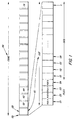
- FIG. 1 is an illustration of an exemplary frame structure in a CDMA system.
- Frame 100 has multiple slots 101, 102, 103, 104, ... , 116.
- Each slot has a pilot portion 120 and a data portion 130.
- the pilot portion 120 has four pilot symbols 121, 122, 123, and 124
- the data portion 130 has multiple data symbols 131, 132, 133, 134, ... , n.
- the pilot symbols 121, 122, 123, and 124 can be used to find different rays.
- the searcher can use a filter that is matched to the pilot symbols (a matched filter) to find the different paths.
- the output of the matched filter is usually referred to as the multipath profile (or the delay profile).
- the delay profile contains more than one spike. The different spikes correspond to the different rays.
- the pilot symbols 121, 122, 123, and 124 can also be used for channel estimation.
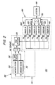
- FIG. 2 is a schematic diagram of the searcher and RAKE receiver portions of a receiver.
- a transmitter (not shown) transmits a signal to receiver 200. Because the signal travels along multiple paths, received signal 201 contains multiple versions of the same signal.
- Searcher 300 uses a matched filter 310 and a peak detector 350 to find and select a set of strongest rays. Searcher 300 can use a second matched filter 320, a slot delay 330, and an accumulator 340 to search more than one slot of frame 100.
- RAKE receiver 400 has six fingers 410, 420, 430, 440, 450, and 460. Each finger is a simple receiver that is configured to receive a different path of the signal 201. For example, finger 410 is configured to receive a path having a time delay of td 1 . Fingers 420, 430, 440, 450, and 460 are configured to receive paths having time delays of td 2 , td 3 , td 4 , td 5 , and td 6 , respectively. The outputs of fingers 410, 420, 430, 440, 450, and 460 are multiplied by individual weights to maximize the received signal-to-noise-and-interference ratio. The weighted outputs are then added by an accumulator 700. The output of accumulator 700 is fed to a detector 800.
- searcher 300 finds a set of rays, but that receiver 200 is a mobile hand-held unit. As receiver 200 moves, these rays are no longer the best rays. If receiver 200 uses weak rays, the signal quality will decrease. The only way that receiver 200 can maintain the same signal quality is to request additional signal power from the base station. Additional signal power increases the amount of interference experienced by the other receivers. The overall interference is minimized when each receiver uses the least amount of signal power possible.
- WO 94/18752 describes a method and apparatus of adaptive maximum likelihood sequence estimation using a variable convergence step size
- EP 0790727 describes a method for demodulating a received signal
- WO 99/29046 describes a method and apparatus for coherently-averaged power estimation.
- a channel estimate generator generates a plurality of channel estimates and a Doppler frequency estimator uses two or more channel estimates to generate a Doppler frequency estimate.
- a Doppler frequency estimator generates a Doppler frequency estimate by calculating the normalized distance between two consecutive channel estimates.
- a receiver uses a Doppler frequency estimate to either (1) adjust the receiver, (2) estimate the velocity of the receiver, (3) determine whether it is necessary to search for new paths, or (4) predict or track new paths.
- the receiver uses a moving average of Doppler frequency estimates to either (1) adjust the receiver, (2) estimate the velocity of the receiver, (3) determine whether it is necessary to search for new paths, or (4) predict or track new paths.
- the receiver uses a weighted combination of Doppler frequency estimates from different paths of a received signal to either (1) adjust the receiver, (2) estimate the velocity of the receiver, (3) determine whether it is necessary to search for new paths, or (4) predict or track new paths.
- An advantage of the invention is that the receiver can estimate the Doppler frequency from the received signal itself. Another advantage is that the need to operate the matched filter is reduced.
- FIG. 1 is an illustration of an exemplary frame structure in a CDMA system.
- FIG. 2 is a schematic diagram of the searcher and RAKE receiver portions of a receiver.
- FIG. 3 is a schematic diagram of a RAKE finger.
- each finger is a simple receiver that is configured to receive a different path of signal 201.
- finger 410 is configured to receive a signal from one of the paths 411.
- Finger 410 can be configured by either shifting the received signal 201 or the despreading code 112.
- despreading code 112 is a long code that spans a large number of symbols. Long code 112 is used to separate, for example, different base stations.
- a short code is a code that spans a single symbol.
- a short code is used to separate, for example, different users in a particular cell.
- integrator 514 uses the short code to obtain individual symbols.
- the individual symbols are divided into pilot symbols 521, 522, 523, and 524 and information symbols 531, 532, 533, ... , n.
- a channel estimate is a measure of the channel's amplitude and phase distortion.
- the receiver has to generate channel estimates for each finger.
- the channel estimate in finger 410 is different from the channel estimate in, for example, finger 420 because finger 410 and finger 420 are configured to receive signals that traveled along different paths.
- the easiest way to generate channel estimate 601 is to compare pilot symbols 521, 522, 523, and 524 with the known pilot symbols 121, 122, 123, and 124.
- combiner 525 can average the product of known pilot 121 with received pilot 521, known pilot 122 with received pilot 522, known pilot 123 with received pilot 523, and known pilot 124 with received pilot 524.
- Channel estimator 527 uses the average from combiner 525 to generate a channel estimate 601.
- FIG. 4 is a graph of the amplitude and phase variation of consecutive channel estimates.
- the channel estimates are from, for example, one of the fingers 410, 420, 430, 440, 450, or 460. Consecutive channel estimates, which are shown as an asterisk, are connected by a line.
- the amplitude and phase variation of, for example, channel estimates 601, 602, 603, and 604 depends on (1) the Rayleigh distribution of the channel and (2) the Doppler frequency of the receiver.
- a Doppler frequency estimator can be configured to use two or more channel estimates to generate a Doppler frequency estimate.
- Doppler frequency estimator 610 uses channel estimates 601 and 602 to generate Doppler frequency estimate 641.
- a normalizer 620 divides channel estimates 601 and 602 by their corresponding lengths to generate normalized channel estimates 621 and 622.
- a subtractor 630 subtracts normalized channel estimate 622 from normalized channel estimate 621 to generate difference 631.
- a multiplier 640 multiplies difference 631 with a constant to generate Doppler frequency estimate 641.
- Doppler frequency estimate 641 can be used to (1) adjust the receiver, (2) estimate the velocity of the receiver, (3) determine whether it is necessary to search for new paths, and/or (4) predict or track new paths.
- Velocity estimator 680 uses Doppler frequency estimate 641 to generate velocity estimate 681.
- Channel estimate 601 may represent a channel estimate from a pilot symbol in slot 101 and channel estimate 602 may represent a channel estimate from slot 101 or slot 102. Or alternatively, channel estimate 601 may represent an average of consecutive channel estimates from slot 101, and channel estimate 602 may represent an average of consecutive channel estimates from slot 102.
- FIG. 6 is a schematic diagram of a Doppler frequency estimator.
- the change in the Doppler frequency can be quite slow. It may be advantageous in some cases to use a moving average of, for example, sixty-four channel estimates.
- a shift register or memory bank can be used to store a plurality of normalized channel estimates. Or alternatively, a shift register or a memory bank can be used to store a plurality of Doppler frequency estimates.
- a combiner 650 can sum and average the resulting channel estimates.
- Doppler frequency estimate 651 can be used to (1) adjust the receiver, (2) estimate the velocity of the receiver, (3) determine whether it is necessary to search for new paths, and/or (4) predict new paths.
- the optimum number of fingers, the weighting of the fingers, and whether to use a moving average in some or all of the fingers depends on, inter alia, the mobile station's environment, the distance between the mobile station and the base station, the speed of the mobile station, and the complexity of the receiver.
Landscapes
- Engineering & Computer Science (AREA)
- Computer Networks & Wireless Communication (AREA)
- Signal Processing (AREA)
- Power Engineering (AREA)
- Mobile Radio Communication Systems (AREA)
- Position Fixing By Use Of Radio Waves (AREA)
- Radar Systems Or Details Thereof (AREA)
Claims (22)
- Dispositif de réception d'un signal, le dispositif comprenant :un générateur d'estimation de canal (527), le générateur d'estimation de canal (527) étant configuré pour générer une pluralité d'estimations de canal ;caractérisé en ce que le dispositif comprend en outre :un estimateur de fréquence Doppler (610), l'estimateur de fréquence Doppler (510) étant configuré pour utiliser deux ou plus estimations de canal pour générer une estimation de fréquence Doppler, dans lequel l'estimateur de fréquence Doppler (610) comprend un dispositif normalisateur (620), le dispositif normalisateur (620) étant configuré pour normaliser au moins deux estimations de canal.
- Dispositif selon la revendication 1, l'estimateur de fréquence Doppler (610) comprenant en outre un soustracteur (630), le soustracteur (630) étant configuré pour calculer une différence entre lesdites au moins deux estimations de canal normalisées.
- Dispositif selon la revendication 2, l'estimateur de fréquence Doppler (610) comprenant en outre un multiplicateur (640), le multiplicateur (640) étant configuré pour multiplier la différence par une constante.
- Dispositif selon la revendication 1, l'estimateur de fréquence Doppler (610) comprenant un dispositif normalisateur (620), le dispositif normalisateur (620) étant configuré pour normaliser au moins deux estimations de canal consécutives.
- Dispositif selon la revendication 4, l'estimateur de fréquence Doppler (610) comprenant en outre un soustracteur (630), le soustracteur (630) étant configuré pour calculer une différence entre lesdites au moins deux estimations de canal normalisées consécutives.
- Dispositif selon la revendication 5, l'estimateur de fréquence Doppler (610) comprenant en outre un multiplicateur (640), le multiplicateur (640) étant configuré pour multiplier la différence par une constante.
- Dispositif selon la revendication 6, dans lequel Ch(k) et Ch-k-1) sont des estimations de canal consécutives et l'estimation de fréquence Doppler est donnée par l'équation :

- Dispositif selon la revendication 1, le dispositif comprenant en outre un estimateur de vitesse, l'estimateur de vitesse étant configuré pour utiliser l'estimation de fréquence Doppler pour générer une estimation de vitesse.
- Dispositif selon la revendication 1, le dispositif comprenant en outre un combinateur (650), le combinateur (650) étant configuré pour calculer la moyenne d'une pluralité d'estimations de fréquence Doppler.
- Dispositif selon la revendication 9, le dispositif comprenant en outre un estimateur de vitesse, l'estimateur de vitesse étant configuré pour utiliser la moyenne pour générer une estimation de vitesse.
- Dispositif selon la revendication 1, le générateur d'estimation de canal (527) étant configuré pour recevoir un premier groupe de symboles pilotes.
- Dispositif selon la revendication 11, le générateur d'estimation de canal (527) étant configuré pour recevoir un second groupe de symboles pilotes, le second groupe de symboles pilotes étant séparé du premier groupe de symboles pilotes par un groupe de symboles d'information.
- Dispositif selon la revendication 12, l'estimateur de fréquence Doppler (610) étant configuré pour utiliser une estimation de canal provenant du premier groupe de symboles pilotes et une estimation de canal provenant du second groupe de symboles pilotes pour générer l'estimation de fréquence Doppler.
- Dispositif selon la revendication 13, l'estimateur de fréquence Doppler (610) étant configuré pour utiliser une moyenne des estimations de canal du premier groupe de symboles pilotes et une moyenne d'estimations de canal provenant du second groupe de symboles pilotes pour générer l'estimation de fréquence Doppler.
- Dispositif de réception d'un signal de spectre de lecture, le dispositif comprenant :une pluralité de doigts (410,420,430,440,450,460) ;un dispositif de recherche (300), le dispositif de recherche (300) étant configuré pour trouver un conduit pour chaque doigt ; et un dispositif de réception d'un signal selon la revendication 1 ;dans lequel l'estimateur de canal (527) est configuré pour générer une pluralité d'estimations de canal pour un des doigts ; et l'estimateur de fréquence Doppler (610) est configuré pour utiliser deux ou plus estimations de canal provenant d'un desdits doigts pour générer l'estimation de fréquence Doppler.
- Dispositif selon la revendication 15, dans lequel l'estimation de fréquence Doppler est utilisée pour ajuster au moins un des doigts.
- Dispositif selon la revendication 15, dans lequel le dispositif de recherche (300) utilise l'estimation de fréquence Doppler pour déterminer si rechercher de nouveaux conduits.
- Dispositif selon la revendication 15, dans lequel l'estimation de fréquence Doppler est utilisée pour prédire l'occurrence de nouveaux conduits.
- Dispositif selon la revendication 15, dans lequel les estimations de canal provenant du doigt le plus fort sont utilisées pour générer l'estimation de fréquence Doppler.
- Dispositif selon la revendication 15, dans lequel les estimations de canal provenant d'un doigt autre que le doigt le plus fort sont utilisées pour générer l'estimation de fréquence Doppler.
- Dispositif selon la revendication 15, le dispositif comprenant en outre une pluralité d'estimateurs de canal (527) et une pluralité d'estimateurs de fréquence Doppler (610), chaque estimateur de fréquence Doppler (610) étant configuré pour utiliser deux ou plusieurs estimations de canal provenant d'un estimateur de canal différent (527) pour générer une estimation de fréquence Doppler.
- Dispositif selon la revendication 21, le dispositif comprenant en outre un combinateur (670), le combinateur (670) étant configuré pour calculer une combinaison pondérée d'estimations de fréquence Doppler provenant d'au moins deux des estimateurs de fréquence Doppler (610).
Applications Claiming Priority (3)
| Application Number | Priority Date | Filing Date | Title |
|---|---|---|---|
| US09/387,788 US6850505B1 (en) | 1999-09-01 | 1999-09-01 | Method and apparatus for Doppler frequency estimation |
| US387788 | 1999-09-01 | ||
| PCT/EP2000/008369 WO2001017185A1 (fr) | 1999-09-01 | 2000-08-28 | Estimation, dans un recepteur en rateau, de la vitesse de changement de voie |
Publications (2)
| Publication Number | Publication Date |
|---|---|
| EP1212871A1 EP1212871A1 (fr) | 2002-06-12 |
| EP1212871B1 true EP1212871B1 (fr) | 2012-10-31 |
Family
ID=23531377
Family Applications (1)
| Application Number | Title | Priority Date | Filing Date |
|---|---|---|---|
| EP00958506A Expired - Lifetime EP1212871B1 (fr) | 1999-09-01 | 2000-08-28 | Estimation, dans un recepteur en rateau, de la vitesse de changement de voie |
Country Status (9)
| Country | Link |
|---|---|
| US (1) | US6850505B1 (fr) |
| EP (1) | EP1212871B1 (fr) |
| JP (1) | JP4515680B2 (fr) |
| CN (1) | CN1158820C (fr) |
| AU (1) | AU7000100A (fr) |
| ES (1) | ES2395397T3 (fr) |
| MY (1) | MY122571A (fr) |
| PT (1) | PT1212871E (fr) |
| WO (1) | WO2001017185A1 (fr) |
Families Citing this family (21)
| Publication number | Priority date | Publication date | Assignee | Title |
|---|---|---|---|---|
| JP3407706B2 (ja) | 1999-11-30 | 2003-05-19 | 日本電気株式会社 | Cdma方式携帯電話装置及びそれに用いるドライブモード設定/解除方法 |
| US20020176485A1 (en) * | 2001-04-03 | 2002-11-28 | Hudson John E. | Multi-cast communication system and method of estimating channel impulse responses therein |
| KR100405657B1 (ko) * | 2001-05-02 | 2003-11-14 | 엘지전자 주식회사 | 무선통신 시스템의 주파수 추정방법 및 장치 |
| CN1156179C (zh) * | 2001-09-03 | 2004-06-30 | 信息产业部电信传输研究所 | 一种信道估计平均区间的动态调整方法和装置 |
| DE60314838T2 (de) * | 2003-04-04 | 2007-10-25 | Mitsubishi Denki K.K. | Verfahren zum Senden von Daten in einem Telekommunikationssystem |
| US7580447B2 (en) * | 2003-05-21 | 2009-08-25 | Nec Corporation | Reception device and radio communication system using the same |
| KR100794985B1 (ko) * | 2003-07-14 | 2008-01-16 | 인터디지탈 테크날러지 코포레이션 | 클러스터 다중 경로 간섭 억제 회로를 갖는 고성능 무선수신기 |
| KR101002857B1 (ko) * | 2003-09-16 | 2010-12-21 | 삼성전자주식회사 | 이동통신 시스템에서 이동단말의 속도 추정 방법 및 장치 |
| KR101009827B1 (ko) * | 2003-09-16 | 2011-01-19 | 삼성전자주식회사 | 이동통신 시스템에서 이동단말의 속도 추정 장치 및 방법 |
| US20060045192A1 (en) * | 2004-08-25 | 2006-03-02 | Hiroshi Hayashi | Method and apparatus for pilot channel transmission and reception within a multi-carrier communication system |
| CN100362903C (zh) * | 2005-05-11 | 2008-01-16 | 北京北方烽火科技有限公司 | 一种用于宽带码分多址系统的异系统硬切换方法 |
| JP2007006105A (ja) * | 2005-06-23 | 2007-01-11 | Nec Corp | 無線基地局及びドップラー周波数推定方法 |
| KR100630495B1 (ko) | 2005-08-19 | 2006-10-02 | 한양대학교 산학협력단 | 무선 통신 시스템의 페이딩 채널 시뮬레이션 방법 및 이를구현하기 위한 프로그램을 기록한 기록매체 |
| US7647049B2 (en) * | 2006-07-12 | 2010-01-12 | Telefonaktiebolaget L M Ericsson (Publ) | Detection of high velocity movement in a telecommunication system |
| EP1983656A1 (fr) * | 2007-04-19 | 2008-10-22 | MediaTek Inc. | Design de filtre partagé pour faire la moyenne de symboles de pilote dans des doigts du Rake dans des systèmes WCDMA |
| WO2009079848A1 (fr) * | 2007-12-21 | 2009-07-02 | Zte Corporation | Procédé pour estimer un étalement de spectre de fréquence et une vitesse d'une station mobile |
| JP5320811B2 (ja) * | 2008-05-13 | 2013-10-23 | 富士通株式会社 | Rake受信機、基地局装置、受信制御方法および受信制御プログラム |
| CN101667855B (zh) * | 2009-09-04 | 2012-10-10 | 凌阳电通科技股份有限公司 | 多普勒频率的估测系统及方法 |
| US8644436B2 (en) * | 2012-02-17 | 2014-02-04 | Alcatel Lucent | Method and apparatus for enhanced uplink general rake channel estimation |
| US9584974B1 (en) * | 2016-05-11 | 2017-02-28 | Cognitive Systems Corp. | Detecting motion based on reference signal transmissions |
| DE102020202890B3 (de) * | 2020-03-06 | 2021-07-08 | Continental Automotive Gmbh | Verfahren und Kommunikationsvorrichtung zum Kompensieren von Doppler-Effekten in empfangenen drahtlosen Kommunikationssignalen |
Family Cites Families (14)
| Publication number | Priority date | Publication date | Assignee | Title |
|---|---|---|---|---|
| US4914699A (en) * | 1988-10-11 | 1990-04-03 | Itt Corporation | High frequency anti-jam communication system terminal |
| JPH06502291A (ja) * | 1991-06-27 | 1994-03-10 | テレフオンアクチーボラゲツト エル エム エリクソン | 移動局のドプラー周波数を見積る方法及び装置 |
| US5577068A (en) * | 1992-06-08 | 1996-11-19 | Ericsson Ge Mobile Communications Inc. | Generalized direct update viterbi equalizer |
| US5818876A (en) * | 1993-02-01 | 1998-10-06 | Motorola, Inc. | Method and apparatus of adaptive maximum likelihood sequence estimation using a variable convergence step size |
| TW351886B (en) * | 1993-09-27 | 1999-02-01 | Ericsson Telefon Ab L M | Using two classes of channels with different capacity |
| WO1995024086A2 (fr) * | 1994-02-25 | 1995-09-08 | Philips Electronics N.V. | Systeme d'emission numerique a acces multiples, poste radio de base et recepteur utilisables dans un tel systeme |
| EP0790727A3 (fr) | 1996-02-19 | 1999-06-23 | Ascom Tech Ag | Procédé de démodulation d'un signal reçu |
| US6067315A (en) * | 1997-12-04 | 2000-05-23 | Telefonaktiebolaget Lm Ericsson | Method and apparatus for coherently-averaged power estimation |
| JP3805520B2 (ja) * | 1998-01-28 | 2006-08-02 | 富士通株式会社 | 移動通信における速度推定装置および方法 |
| JPH11234190A (ja) * | 1998-02-12 | 1999-08-27 | Oki Electric Ind Co Ltd | 最大ドップラー周波数観測回路、無線チャネル推定回路及び物体移動速度観測回路 |
| US6470000B1 (en) * | 1998-10-14 | 2002-10-22 | Agere Systems Guardian Corp. | Shared correlator system and method for direct-sequence CDMA demodulation |
| US6377813B1 (en) * | 1998-12-03 | 2002-04-23 | Nokia Corporation | Forward link closed loop power control for a third generation wideband CDMA system |
| US6424642B1 (en) * | 1998-12-31 | 2002-07-23 | Texas Instruments Incorporated | Estimation of doppler frequency through autocorrelation of pilot symbols |
| US6542562B1 (en) * | 1999-02-09 | 2003-04-01 | Telefonaktiebolaget Lm Ericsson (Publ) | Approximated MMSE-based channel estimator in a mobile communication system |
-
1999
- 1999-09-01 US US09/387,788 patent/US6850505B1/en not_active Expired - Lifetime
-
2000
- 2000-08-28 WO PCT/EP2000/008369 patent/WO2001017185A1/fr not_active Ceased
- 2000-08-28 EP EP00958506A patent/EP1212871B1/fr not_active Expired - Lifetime
- 2000-08-28 CN CNB00814852XA patent/CN1158820C/zh not_active Expired - Lifetime
- 2000-08-28 ES ES00958506T patent/ES2395397T3/es not_active Expired - Lifetime
- 2000-08-28 AU AU70001/00A patent/AU7000100A/en not_active Abandoned
- 2000-08-28 JP JP2001521011A patent/JP4515680B2/ja not_active Expired - Fee Related
- 2000-08-28 PT PT958506T patent/PT1212871E/pt unknown
- 2000-08-29 MY MYPI20003971A patent/MY122571A/en unknown
Also Published As
| Publication number | Publication date |
|---|---|
| JP4515680B2 (ja) | 2010-08-04 |
| ES2395397T3 (es) | 2013-02-12 |
| EP1212871A1 (fr) | 2002-06-12 |
| CN1382335A (zh) | 2002-11-27 |
| AU7000100A (en) | 2001-03-26 |
| WO2001017185A1 (fr) | 2001-03-08 |
| PT1212871E (pt) | 2012-12-24 |
| MY122571A (en) | 2006-04-29 |
| WO2001017185A9 (fr) | 2002-09-06 |
| CN1158820C (zh) | 2004-07-21 |
| JP2003508969A (ja) | 2003-03-04 |
| US6850505B1 (en) | 2005-02-01 |
| WO2001017185A8 (fr) | 2004-02-19 |
Similar Documents
| Publication | Publication Date | Title |
|---|---|---|
| EP1212871B1 (fr) | Estimation, dans un recepteur en rateau, de la vitesse de changement de voie | |
| US6711384B2 (en) | Apparatus and method for controlling communications based on moving speed | |
| US6370397B1 (en) | Search window delay tracking in code division multiple access communication systems | |
| AU760919B2 (en) | Cdma receiving method and circuit | |
| EP1323236B1 (fr) | Procede et appareil pour la commande de frequence automatique dans un recepteur cdma | |
| CN100459766C (zh) | 用来在移动通信中估计速度的方法 | |
| US20030012267A1 (en) | CDMA receiver, and searcher in a CDMA receiver | |
| EP0808031B1 (fr) | Demodulateur multi-voies à spectre étalé | |
| JP4295112B2 (ja) | コード化信号処理エンジンのための干渉行列の構成 | |
| CN1622653A (zh) | 一种用于对td-scdma系统下行链路进行频率估测的装置和方法 | |
| KR20000016966A (ko) | 무선신호에서데이터를복구하는수신기및방법 | |
| US20070116103A1 (en) | Method and Apparatus for Configuring a RAKE Receiver | |
| KR100361408B1 (ko) | Cdma 통신을 위한 동기포착회로 | |
| US6650686B1 (en) | Spread spectrum communication system and handover method therein | |
| US7106783B2 (en) | Method and apparatus for searching multipaths of mobile communication system | |
| US6490315B2 (en) | Code synchronization method and receiver | |
| US20030114125A1 (en) | Interference suppression in a radio receiver | |
| US7352799B2 (en) | Channel estimation in spread spectrum system | |
| JP3794617B2 (ja) | Cdma移動通信方式における移動局のセルサーチ方法、並びに、cdma移動通信システム | |
| RU2297713C2 (ru) | Способ приема многолучевого сигнала и устройство для его осуществления | |
| EP1672808B1 (fr) | Sélection des valeurs de retard pour un récepteur du type RAKE | |
| JP3228311B2 (ja) | 受信装置 | |
| WO2006066765A1 (fr) | Selection de valeurs de retard de cretes pour un recepteur en rateau |
Legal Events
| Date | Code | Title | Description |
|---|---|---|---|
| PUAI | Public reference made under article 153(3) epc to a published international application that has entered the european phase |
Free format text: ORIGINAL CODE: 0009012 |
|
| AK | Designated contracting states |
Kind code of ref document: A1 Designated state(s): AT BE CH CY DE DK ES FI FR GB GR IE IT LI LU MC NL PT SE |
|
| AX | Request for extension of the european patent |
Free format text: AL;LT;LV;MK;RO;SI |
|
| 17P | Request for examination filed |
Effective date: 20020327 |
|
| RAP1 | Party data changed (applicant data changed or rights of an application transferred) |
Owner name: TELEFONAKTIEBOLAGET LM ERICSSON (PUBL) |
|
| 17Q | First examination report despatched |
Effective date: 20091120 |
|
| GRAP | Despatch of communication of intention to grant a patent |
Free format text: ORIGINAL CODE: EPIDOSNIGR1 |
|
| GRAS | Grant fee paid |
Free format text: ORIGINAL CODE: EPIDOSNIGR3 |
|
| GRAA | (expected) grant |
Free format text: ORIGINAL CODE: 0009210 |
|
| AK | Designated contracting states |
Kind code of ref document: B1 Designated state(s): AT BE CH CY DE DK ES FI FR GB GR IE IT LI LU MC NL PT SE |
|
| REG | Reference to a national code |
Ref country code: GB Ref legal event code: FG4D Ref country code: CH Ref legal event code: EP |
|
| REG | Reference to a national code |
Ref country code: AT Ref legal event code: REF Ref document number: 582521 Country of ref document: AT Kind code of ref document: T Effective date: 20121115 |
|
| REG | Reference to a national code |
Ref country code: IE Ref legal event code: FG4D |
|
| REG | Reference to a national code |
Ref country code: PT Ref legal event code: SC4A Free format text: AVAILABILITY OF NATIONAL TRANSLATION Effective date: 20121210 |
|
| REG | Reference to a national code |
Ref country code: DE Ref legal event code: R096 Ref document number: 60047608 Country of ref document: DE Effective date: 20121227 |
|
| REG | Reference to a national code |
Ref country code: ES Ref legal event code: FG2A Ref document number: 2395397 Country of ref document: ES Kind code of ref document: T3 Effective date: 20130212 |
|
| REG | Reference to a national code |
Ref country code: NL Ref legal event code: T3 |
|
| REG | Reference to a national code |
Ref country code: AT Ref legal event code: MK05 Ref document number: 582521 Country of ref document: AT Kind code of ref document: T Effective date: 20121031 |
|
| PG25 | Lapsed in a contracting state [announced via postgrant information from national office to epo] |
Ref country code: FI Free format text: LAPSE BECAUSE OF FAILURE TO SUBMIT A TRANSLATION OF THE DESCRIPTION OR TO PAY THE FEE WITHIN THE PRESCRIBED TIME-LIMIT Effective date: 20121031 Ref country code: SE Free format text: LAPSE BECAUSE OF FAILURE TO SUBMIT A TRANSLATION OF THE DESCRIPTION OR TO PAY THE FEE WITHIN THE PRESCRIBED TIME-LIMIT Effective date: 20121031 |
|
| PG25 | Lapsed in a contracting state [announced via postgrant information from national office to epo] |
Ref country code: CY Free format text: LAPSE BECAUSE OF FAILURE TO SUBMIT A TRANSLATION OF THE DESCRIPTION OR TO PAY THE FEE WITHIN THE PRESCRIBED TIME-LIMIT Effective date: 20121031 Ref country code: GR Free format text: LAPSE BECAUSE OF FAILURE TO SUBMIT A TRANSLATION OF THE DESCRIPTION OR TO PAY THE FEE WITHIN THE PRESCRIBED TIME-LIMIT Effective date: 20130201 Ref country code: BE Free format text: LAPSE BECAUSE OF FAILURE TO SUBMIT A TRANSLATION OF THE DESCRIPTION OR TO PAY THE FEE WITHIN THE PRESCRIBED TIME-LIMIT Effective date: 20121031 |
|
| PG25 | Lapsed in a contracting state [announced via postgrant information from national office to epo] |
Ref country code: AT Free format text: LAPSE BECAUSE OF FAILURE TO SUBMIT A TRANSLATION OF THE DESCRIPTION OR TO PAY THE FEE WITHIN THE PRESCRIBED TIME-LIMIT Effective date: 20121031 |
|
| PG25 | Lapsed in a contracting state [announced via postgrant information from national office to epo] |
Ref country code: DK Free format text: LAPSE BECAUSE OF FAILURE TO SUBMIT A TRANSLATION OF THE DESCRIPTION OR TO PAY THE FEE WITHIN THE PRESCRIBED TIME-LIMIT Effective date: 20121031 |
|
| PG25 | Lapsed in a contracting state [announced via postgrant information from national office to epo] |
Ref country code: IT Free format text: LAPSE BECAUSE OF FAILURE TO SUBMIT A TRANSLATION OF THE DESCRIPTION OR TO PAY THE FEE WITHIN THE PRESCRIBED TIME-LIMIT Effective date: 20121031 |
|
| PLBE | No opposition filed within time limit |
Free format text: ORIGINAL CODE: 0009261 |
|
| STAA | Information on the status of an ep patent application or granted ep patent |
Free format text: STATUS: NO OPPOSITION FILED WITHIN TIME LIMIT |
|
| 26N | No opposition filed |
Effective date: 20130801 |
|
| REG | Reference to a national code |
Ref country code: DE Ref legal event code: R097 Ref document number: 60047608 Country of ref document: DE Effective date: 20130801 |
|
| REG | Reference to a national code |
Ref country code: CH Ref legal event code: PL |
|
| PG25 | Lapsed in a contracting state [announced via postgrant information from national office to epo] |
Ref country code: CH Free format text: LAPSE BECAUSE OF NON-PAYMENT OF DUE FEES Effective date: 20130831 Ref country code: LI Free format text: LAPSE BECAUSE OF NON-PAYMENT OF DUE FEES Effective date: 20130831 Ref country code: MC Free format text: LAPSE BECAUSE OF FAILURE TO SUBMIT A TRANSLATION OF THE DESCRIPTION OR TO PAY THE FEE WITHIN THE PRESCRIBED TIME-LIMIT Effective date: 20121031 |
|
| REG | Reference to a national code |
Ref country code: IE Ref legal event code: MM4A |
|
| REG | Reference to a national code |
Ref country code: FR Ref legal event code: ST Effective date: 20140430 |
|
| PG25 | Lapsed in a contracting state [announced via postgrant information from national office to epo] |
Ref country code: IE Free format text: LAPSE BECAUSE OF NON-PAYMENT OF DUE FEES Effective date: 20130828 |
|
| PG25 | Lapsed in a contracting state [announced via postgrant information from national office to epo] |
Ref country code: FR Free format text: LAPSE BECAUSE OF NON-PAYMENT OF DUE FEES Effective date: 20130902 |
|
| PG25 | Lapsed in a contracting state [announced via postgrant information from national office to epo] |
Ref country code: LU Free format text: LAPSE BECAUSE OF NON-PAYMENT OF DUE FEES Effective date: 20130828 |
|
| PGFP | Annual fee paid to national office [announced via postgrant information from national office to epo] |
Ref country code: NL Payment date: 20190826 Year of fee payment: 20 |
|
| PGFP | Annual fee paid to national office [announced via postgrant information from national office to epo] |
Ref country code: ES Payment date: 20190902 Year of fee payment: 20 Ref country code: PT Payment date: 20190801 Year of fee payment: 20 Ref country code: DE Payment date: 20190828 Year of fee payment: 20 |
|
| PGFP | Annual fee paid to national office [announced via postgrant information from national office to epo] |
Ref country code: GB Payment date: 20190827 Year of fee payment: 20 |
|
| REG | Reference to a national code |
Ref country code: DE Ref legal event code: R071 Ref document number: 60047608 Country of ref document: DE |
|
| REG | Reference to a national code |
Ref country code: NL Ref legal event code: MK Effective date: 20200827 |
|
| REG | Reference to a national code |
Ref country code: GB Ref legal event code: PE20 Expiry date: 20200827 |
|
| PG25 | Lapsed in a contracting state [announced via postgrant information from national office to epo] |
Ref country code: GB Free format text: LAPSE BECAUSE OF EXPIRATION OF PROTECTION Effective date: 20200827 Ref country code: PT Free format text: LAPSE BECAUSE OF EXPIRATION OF PROTECTION Effective date: 20200907 |
|
| REG | Reference to a national code |
Ref country code: ES Ref legal event code: FD2A Effective date: 20220128 |
|
| PG25 | Lapsed in a contracting state [announced via postgrant information from national office to epo] |
Ref country code: ES Free format text: LAPSE BECAUSE OF EXPIRATION OF PROTECTION Effective date: 20200829 |