EP1213074A2 - Bohrer für Gestein - Google Patents
Bohrer für Gestein Download PDFInfo
- Publication number
- EP1213074A2 EP1213074A2 EP01810602A EP01810602A EP1213074A2 EP 1213074 A2 EP1213074 A2 EP 1213074A2 EP 01810602 A EP01810602 A EP 01810602A EP 01810602 A EP01810602 A EP 01810602A EP 1213074 A2 EP1213074 A2 EP 1213074A2
- Authority
- EP
- European Patent Office
- Prior art keywords
- drill
- helical
- head
- drill according
- shank
- Prior art date
- Legal status (The legal status is an assumption and is not a legal conclusion. Google has not performed a legal analysis and makes no representation as to the accuracy of the status listed.)
- Withdrawn
Links
Images

Classifications
-
- B—PERFORMING OPERATIONS; TRANSPORTING
- B23—MACHINE TOOLS; METAL-WORKING NOT OTHERWISE PROVIDED FOR
- B23B—TURNING; BORING
- B23B51/00—Tools for drilling machines
- B23B51/02—Twist drills
-
- B—PERFORMING OPERATIONS; TRANSPORTING
- B28—WORKING CEMENT, CLAY, OR STONE
- B28D—WORKING STONE OR STONE-LIKE MATERIALS
- B28D1/00—Working stone or stone-like materials, e.g. brick, concrete or glass, not provided for elsewhere; Machines, devices, tools therefor
- B28D1/14—Working stone or stone-like materials, e.g. brick, concrete or glass, not provided for elsewhere; Machines, devices, tools therefor by boring or drilling
- B28D1/146—Tools therefor
-
- B—PERFORMING OPERATIONS; TRANSPORTING
- B23—MACHINE TOOLS; METAL-WORKING NOT OTHERWISE PROVIDED FOR
- B23B—TURNING; BORING
- B23B2226/00—Materials of tools or workpieces not comprising a metal
- B23B2226/75—Stone, rock or concrete
-
- B—PERFORMING OPERATIONS; TRANSPORTING
- B23—MACHINE TOOLS; METAL-WORKING NOT OTHERWISE PROVIDED FOR
- B23B—TURNING; BORING
- B23B2251/00—Details of tools for drilling machines
- B23B2251/40—Flutes, i.e. chip conveying grooves
- B23B2251/406—Flutes, i.e. chip conveying grooves of special form not otherwise provided for
Definitions
- the invention relates to a drill, appropriately used with at least one partially rotating and striking hand tool device for drilling rock like Concrete and brick, which is advantageously designed for direct assembly of pipe elements.
- a drill for rock faces on both sides to an elongated with a helical one Provided spiral grooves, a receiving area for the connection with the Hand tool and a drill head provided with hard material inserts.
- the spiral groove is according to the helical pitch and the helical cross section within the Core diameter of the shank and the outer diameter of the drill.
- such a drill has a reference to the Diameter of the shank and the drill head corresponding to the mounting hole usual rock drill a much lower torsional stiffness of the shaft and a smaller mounting surface of the drill head for a hard metal insert.
- Drills with different pitches of the helix are known, but they are do not create drill holes that are larger than the respective drill diameter.
- DE19707608A1 discloses a drill for producing conical bores, which are particularly suitable for screw connections. To do this, the drill shows itself up to a point of tapered shaft with helical spiral grooves. On However, such a drill does not produce drill holes that are larger than the respective drill diameter are.
- the object of the invention is to realize a drill for rock, which despite the geometric restrictions for the direct fastening of pipe elements high torsional rigidity with a large mounting surface and sufficient removal of the drilling dust combined.
- the shaft essentially has a helical path, the axial helical groove length of each Related free volume of the helical groove in each case axially facing away from the drill head Area of the drill is larger.
- This solution is based on the knowledge that a drilling dust jam as a result of Twist of the drilling dust and thus the relative speed difference between the helix and Drilling powder is created.
- increasing swirl reduces the volume of drilling dust produced, comes there is an increasing compaction of the drilling dust, which ultimately leads to a blockage can lead.
- the compacted drilling dust rotates with the shaft, causing further compression associated with a sharp increase in temperature of the subsequent drilling dust, which is ultimately caused by an explosive Deflagration freed from coercion.
- the helical pitch can be increased reduced, due to the inner diameter of the tubular element as well as the eccentric Movement around the tip of the head in the head area Diameter can advantageously be designed as a core diameter.
- the core diameter advantageously takes the entire geometrical area in the area of the drill head available diameter. This makes a maximum with regard to the shaft possible torsional rigidity is achieved and the geometrical position of the drill head available diameters completely for the attachment of a hard material plate or a Full hard head available. Because of the reduced at a given load Stress on the drill increases its service life.
- drills for the direct assembly of Pipe elements can be realized, which are also suitable for hard rock such as concrete. moreover longer and / or thinner drills are possible.
- the two helical gears of the Drills with a slope of 30 ° are furthermore advantageously almost rectangular and narrow executed, whereby with a given outer diameter and one, with respect the discharge amount for the roughly twice as large drilling dust volume of the under optimal Operating conditions of removed rock, given helical groove cross section maximum core diameter.
- the drill head is equipped with a recessed hard material plate or as a full hard material head trained and the hard material advantageously brazed or friction welded to the rest of the drill.
- the eccentrically arranged to the axis of the drill goes into a, in essentially axially parallel, guide area over which the drill head in the this eccentrically arranged tip leads guide hole.
- To this management area closes in the opposite of the eccentric offset of the management tip Half space at least one radially outside arranged cutting edge, which is the actual Assembly hole created. Due to the eccentric guidance of the drill head, this mounting hole has a much larger diameter than the drill head itself.
- the radially outer cutting edge advantageously extends over the adjacent diameter of the shaft, which creates a space for the tubular element between the mounting hole and the area of the shank adjacent to the drill head is created.
- Another advantage is that which extends beyond the adjacent diameter of the shaft extending radially outer cutting edge in the axial transition area than an axially oblique Chamfer formed, which after direct assembly of the tubular element when pulling back the drill serves as the leading edge of the drill head in the tubular element.
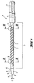
- FIG. 1 shows a drill 1 for rock on both sides to an elongated, with helical Provided spiral grooves 2, shaft 3 a receiving area 4 for connection with the hand tool and a drill head 5 designed as a solid material head with a radially outer cutting edge 6.
- a two-speed spiral gear 7 tapers with a 30 ° slope axially towards zero in the direction of the drill head 5, as a result of which the helical grooves do not extend axially extend to the drill head 6.
- the drill head 5 has a tip 8 which is arranged eccentrically to the axis A of the drill 1. At the top 8 is included axially parallel guide area 9.
- the radially outer cutting edge 6 extends radially beyond the adjacent area of the shaft 3 and goes over an axial chamfer 10 in this about.
- the helix height as the difference is one in the helical gear 7 Given outer diameter 11 to a core diameter 12 of the shaft 3, whereby a helical groove 2 is formed.
- the core diameter 12 is the same.
- the spiral path 7 forms according to the details X and Y (Fig. 2a / 3a) essentially a rectangular cross section.
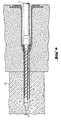
- a drill 1 penetrates a tubular element connected to a mounting element 13 and with this is partially in a drilled mounting hole 14 in a rock 15 arranged by the drill head 5 with an eccentricity E of the tip 8 in a guide hole is guided over its guide area and between the shaft of the drill 1 and the inner wall of the mounting hole 14, a space for the tubular element 13 is available is which when pulling the drill 1 out of the tubular element 13 an introduction of Drill head 5 allows in the end face of the tubular element 13 via the chamfer 10.
Landscapes
- Engineering & Computer Science (AREA)
- Mechanical Engineering (AREA)
- Mining & Mineral Resources (AREA)
- Processing Of Stones Or Stones Resemblance Materials (AREA)
- Earth Drilling (AREA)
- Drilling Tools (AREA)
Abstract
Description
- Fig. 1
- einen erfindungsgemässen Bohrer für Gestein in Seitenansicht
- Fig. 2
- einen Schnitt gem. der Linie II-II in Figur 1 im vergrössertem Massstab
- Fig. 2a
- eine vergrösserte Detaildarstellung gem. dem Ausschnitt X in Figur 1,
- Fig. 3
- einen Schnitt gem. der Linie III-III in Figur 1 im vergrösserten Massstab
- Fig. 3a
- eine vergrösserte Detaildarstellung gem. dem Ausschnitt Y in Figur 1,
- Fig. 4
- einen erfindungsgemässen Bohrer gem. Figur 1 in Verwendung zur Direktmontage von Rohrelementen
Claims (10)
- Bohrer für Gestein mit einem mit Schneiden (6) aus Hartstoff ausgebildeten Bohrkopf (5) und einem Schaft (3) mit wenigstens einem, eine wendelförmige Wendelnut (2) ausbildenden, Wendelgang (7), dadurch gekennzeichnet, dass das je axialer Wendelnutlänge bezogene freie Volumen der Wendelnut (2) am jeweils axial dem Bohrkopf (5) abgewandten Bereich des Bohrers (1) grösser ist.
- Bohrer nach Anspruch 1, dadurch gekennzeichnet, dass ein Wendelgang (7) eine bezüglich eines Kerndurchmessers (12) sich axial zum Bohrkopf (5) hin konisch verjüngende Wendelganghöhe aufweist.
- Bohrer nach Anspruch 1 oder Anspruch 2, dadurch gekennzeichnet, dass bei ansonsten im wesentlichen gleicher Form des Wendelquerschnitts die Wendelganghöhe in einem dem Bohrkopf (5) axial benachbarten Bereich des Schafts (3) reduziert ist.
- Bohrer nach einem der vorherigen Ansprüche, dadurch gekennzeichnet, dass zwei Wendelgänge (7) mit einer konstanten Steigung im Bereich von 20° bis 40° ausgebildet sind.
- Bohrer nach einem der vorherigen Ansprüche, dadurch gekennzeichnet, dass der Wendelnutquerschnitt im wesentlichen rechteckig ausgebildet ist.
- Bohrer nach einem der vorherigen Ansprüche, dadurch gekennzeichnet, dass der Wendelgang (7) in axialer Richtung zum Bohrkopf (5) vollständig ausläuft und im an den Bohrkopf (5) angrenzenden axialen Bereich des Schafts (5) der Kerndurchmesser (12) einen gesamten geometrisch verfügbaren Aussendurchmesser (11) einnimmt.
- Bohrer nach einem der vorherigen Ansprüche, dadurch gekennzeichnet, dass die radial äussere Schneide (6) des Bohrkopfes (5) über eine axiale Fase (10) in den Aussendurchmesser (11) des axial benachbarten Bereiches des Schafts (3) übergeht.
- Bohrer nach einem der vorherigen Ansprüche, dadurch gekennzeichnet, dass der Bohrkopf (5) eine zur Achse des Bohrers (1) exzentrisch versetzte Spitze (8) aufweist.
- Bohrer nach Anspruch 8, dadurch gekennzeichnet, dass sich an die Spitze (8) ein achsparalleler Führungsbereich (9) anschliesst.
- Bohrer nach einem der vorherigen Ansprüche, dadurch gekennzeichnet, dass der Bohrer (1) zur Direktmontage von beim Bohren durchdrungenen Rohrelementen (13) verwendbar ausgestaltet ist.
Applications Claiming Priority (2)
| Application Number | Priority Date | Filing Date | Title |
|---|---|---|---|
| DE10031968 | 2000-06-30 | ||
| DE10031968A DE10031968A1 (de) | 2000-06-30 | 2000-06-30 | Bohrer für Gestein |
Publications (2)
| Publication Number | Publication Date |
|---|---|
| EP1213074A2 true EP1213074A2 (de) | 2002-06-12 |
| EP1213074A3 EP1213074A3 (de) | 2003-10-22 |
Family
ID=7647395
Family Applications (1)
| Application Number | Title | Priority Date | Filing Date |
|---|---|---|---|
| EP01810602A Withdrawn EP1213074A3 (de) | 2000-06-30 | 2001-06-20 | Bohrer für Gestein |
Country Status (3)
| Country | Link |
|---|---|
| EP (1) | EP1213074A3 (de) |
| JP (1) | JP2002052527A (de) |
| DE (1) | DE10031968A1 (de) |
Cited By (3)
| Publication number | Priority date | Publication date | Assignee | Title |
|---|---|---|---|---|
| WO2015026955A1 (en) * | 2013-08-21 | 2015-02-26 | Scianamblo Michael J | Precessional drilling and reaming |
| US9801696B2 (en) | 2013-01-30 | 2017-10-31 | Maillefer Instruments Holding Sárl | Instrument for drilling dental root canals |
| US11510688B2 (en) | 2018-04-18 | 2022-11-29 | Michael J. Scianamblo | Bone matter collection apparatuses |
Families Citing this family (1)
| Publication number | Priority date | Publication date | Assignee | Title |
|---|---|---|---|---|
| CN103317603A (zh) * | 2012-03-18 | 2013-09-25 | 赵兵 | 通过孔内锚固导向器使绳锯机用于地下岩石工程的方法 |
Family Cites Families (4)
| Publication number | Priority date | Publication date | Assignee | Title |
|---|---|---|---|---|
| US2370706A (en) * | 1943-11-29 | 1945-03-06 | Rudolf W Andreasson | Drill |
| GB1329664A (en) * | 1970-09-17 | 1973-09-12 | Fischer Artur | Drill shank/expansion element assembly |
| CA2168889C (en) * | 1993-08-06 | 2003-12-09 | Kennametal Hertel Ag Werkzeuge + Hartstoffe | Twist drill |
| DE29724089U1 (de) * | 1997-06-25 | 1999-12-09 | Drebo Werkzeugfabrik Gmbh, 88361 Altshausen | Bohrer |
-
2000
- 2000-06-30 DE DE10031968A patent/DE10031968A1/de not_active Ceased
-
2001
- 2001-06-20 EP EP01810602A patent/EP1213074A3/de not_active Withdrawn
- 2001-06-22 JP JP2001189195A patent/JP2002052527A/ja active Pending
Cited By (7)
| Publication number | Priority date | Publication date | Assignee | Title |
|---|---|---|---|---|
| US9801696B2 (en) | 2013-01-30 | 2017-10-31 | Maillefer Instruments Holding Sárl | Instrument for drilling dental root canals |
| US10123850B2 (en) | 2013-01-30 | 2018-11-13 | Dentsply Sirona Inc. | Instrument for drilling dental root canals |
| WO2015026955A1 (en) * | 2013-08-21 | 2015-02-26 | Scianamblo Michael J | Precessional drilling and reaming |
| US9271740B2 (en) | 2013-08-21 | 2016-03-01 | Michael J. Scianamblo | Precessional-motion bone and dental drilling tools and bone harvesting apparatus |
| US9277925B2 (en) | 2013-08-21 | 2016-03-08 | Michael J. Scianamblo | Precessional drilling and reaming |
| US10363615B2 (en) | 2013-08-21 | 2019-07-30 | Michael J. Scianamblo | Precessional-motion bone and dental drilling tools and bone harvesting apparatus |
| US11510688B2 (en) | 2018-04-18 | 2022-11-29 | Michael J. Scianamblo | Bone matter collection apparatuses |
Also Published As
| Publication number | Publication date |
|---|---|
| JP2002052527A (ja) | 2002-02-19 |
| DE10031968A1 (de) | 2002-01-10 |
| EP1213074A3 (de) | 2003-10-22 |
Similar Documents
| Publication | Publication Date | Title |
|---|---|---|
| DE3317989C2 (de) | ||
| EP0884448B1 (de) | Gesteinsbohrmeissel mit wendelförmigen Abfuhrnuten | |
| EP0878261B1 (de) | Bohrwerkzeug | |
| DE60016782T2 (de) | Selbstbohrender ankerbolzen | |
| EP0778100B1 (de) | Drehschlag-Wendelbohrer | |
| EP0941794A2 (de) | Bohrwerkzeug | |
| EP0941793A2 (de) | Bohrwerkzeug | |
| DE3407427A1 (de) | Bohrkrone | |
| EP1260296B1 (de) | Bohrer | |
| EP1197630B1 (de) | Wendelbohrer für Gestein | |
| EP0707129A2 (de) | Bohrwerkzeug mit Trägerkörper und Schneidkörpern | |
| EP1316669A2 (de) | Gesteinbohrwerkzeug | |
| DE102008029404A1 (de) | Einsatzelement, Bohrwerkzeug mit Einsatzelement und Verfahren | |
| EP1604793B1 (de) | Bohrer | |
| EP2011958B1 (de) | Erdbohrer | |
| EP3656494B1 (de) | Stufenbohrer | |
| EP0771934B1 (de) | Bohrwerkzeug, insbesondere zur Bearbeitung von Gestein | |
| EP1083295B1 (de) | Bohrwerkzeug | |
| DE3718158C2 (de) | Vorrichtung zur Erzeugung einer Hinterschneidung in einem zylindrisch vorgebohrten Bohrloch | |
| EP1213074A2 (de) | Bohrer für Gestein | |
| DE19709771B4 (de) | Gesteinsbohrer | |
| EP0778390B1 (de) | Drehschlag-Wendelbohrer | |
| DE2211532A1 (de) | Bohrer, insbesondere steinbohrer | |
| DE4326000A1 (de) | Stiftbohrkrone für das schlagende Bohren | |
| CH696928A5 (de) | Kernbohrkrone, insbesondere Diamantbohrkrone, mit verbesserter Spülung. |
Legal Events
| Date | Code | Title | Description |
|---|---|---|---|
| PUAI | Public reference made under article 153(3) epc to a published international application that has entered the european phase |
Free format text: ORIGINAL CODE: 0009012 |
|
| AK | Designated contracting states |
Kind code of ref document: A2 Designated state(s): AT BE CH CY DE DK ES FI FR GB GR IE IT LI LU MC NL PT SE TR |
|
| AX | Request for extension of the european patent |
Free format text: AL;LT;LV;MK;RO;SI |
|
| PUAL | Search report despatched |
Free format text: ORIGINAL CODE: 0009013 |
|
| AK | Designated contracting states |
Kind code of ref document: A3 Designated state(s): AT BE CH CY DE DK ES FI FR GB GR IE IT LI LU MC NL PT SE TR |
|
| AX | Request for extension of the european patent |
Extension state: AL LT LV MK RO SI |
|
| 17P | Request for examination filed |
Effective date: 20040422 |
|
| AKX | Designation fees paid |
Designated state(s): DE DK FR GB IT |
|
| 17Q | First examination report despatched |
Effective date: 20040701 |
|
| STAA | Information on the status of an ep patent application or granted ep patent |
Free format text: STATUS: THE APPLICATION IS DEEMED TO BE WITHDRAWN |
|
| 18D | Application deemed to be withdrawn |
Effective date: 20041112 |