EP1213101A2 - Armoire à outils - Google Patents
Armoire à outils Download PDFInfo
- Publication number
- EP1213101A2 EP1213101A2 EP01830027A EP01830027A EP1213101A2 EP 1213101 A2 EP1213101 A2 EP 1213101A2 EP 01830027 A EP01830027 A EP 01830027A EP 01830027 A EP01830027 A EP 01830027A EP 1213101 A2 EP1213101 A2 EP 1213101A2
- Authority
- EP
- European Patent Office
- Prior art keywords
- cabinet
- box
- bench
- vertical
- correspondence
- Prior art date
- Legal status (The legal status is an assumption and is not a legal conclusion. Google has not performed a legal analysis and makes no representation as to the accuracy of the status listed.)
- Withdrawn
Links
Images




Classifications
-
- B—PERFORMING OPERATIONS; TRANSPORTING
- B25—HAND TOOLS; PORTABLE POWER-DRIVEN TOOLS; MANIPULATORS
- B25H—WORKSHOP EQUIPMENT, e.g. FOR MARKING-OUT WORK; STORAGE MEANS FOR WORKSHOPS
- B25H3/00—Storage means or arrangements for workshops facilitating access to, or handling of, work tools or instruments
-
- A—HUMAN NECESSITIES
- A47—FURNITURE; DOMESTIC ARTICLES OR APPLIANCES; COFFEE MILLS; SPICE MILLS; SUCTION CLEANERS IN GENERAL
- A47B—TABLES; DESKS; OFFICE FURNITURE; CABINETS; DRAWERS; GENERAL DETAILS OF FURNITURE
- A47B46/00—Cabinets, racks or shelf units, having one or more surfaces adapted to be brought into position for use by extending or pivoting
- A47B46/005—Cabinets, racks or shelf units, having one or more surfaces adapted to be brought into position for use by extending or pivoting by displacement in a vertical plane; by rotating about a horizontal axis
Definitions
- the present invention relates to a tool cabinet.
- tools does not mean only traditional working tools such as wrenches, screwdrivers and others, but in a general sense also other working organs or devices such as vices, drills, compressors, soldering irons or others, as well as other articles for ready use, such as screws, nuts, nails and working materials in general.
- Tool boxes and the like for professional or home use are known.
- a defect of such tool boxes stems from the fact that they have a limited containment capacity and they must be housed, when not in use, in respective shelves or cabinet appropriately provided in the house.
- a tool cabinet comprising at least a first main body having generally box-like shape open at the front and defined by a back wall, by a first and a second vertical lateral walls, by a top wall, and by a bottom wall, provided with means able to be opened for the front closure of said box-like body, and provided with appropriate means for supporting tools or the like.
- a housing container is thus provided for tools or the like, having a considerable capacity to contain related tools and requiring no additional furnishing elements or the like.
- the configuration of the present cabinet allows to minimise its size in order to place it even in restricted spaces.
- the present tool container could be placed in the space remaining behind a door of a residential apartment or of a transport van.
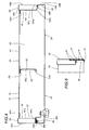
- a first preferred embodiment 10 of the present tool cabinet comprises at least a first box-like containment body 12, presenting a general box-like or prismatic shape - preferably with quadrangular profile - in particular (as shown) with rectangular profile having the long sides positioned vertically.
- Said first body 12 of the present embodiment of cabinet comprises a back wall 14, a first and a second vertical lateral walls 16, 18, a top wall 20, a bottom wall 22.
- Appropriate means in particular in the form of a door indicated with the reference number 13, are provided to guarantee the front closure and the opening of said box-like body 12.
- the present main box-like body 12 advantageously comprises a first and a second support uprights 16, 18, in the form of vertical cups, which are positioned in correspondence with the opposite transverse flanks of the box-like body and define part of the load-bearing frame of the present cabinet.
- said first and second lateral uprights 16, 18 extend longitudinally wholly defining the lateral walls 16, 18 of the box-like body 12.
- Said lateral uprights 16, 18 define structural elements having considerable flexural rigidity and contribute to form a cabinet having a particular strong and compact structure.
- said main box-like body 12 is obtained starting from a first element or plate sheet, globally indicated with the reference number 14', which is appropriately shaped in such a way as to have an ample central part 14, defining said back wall of the box-like body, and respective folded lateral parts 16', 18' (clearly shown in Figure 4), which extend substantially perpendicular to said back wall 14 and define the rear and external lateral part of said first and second lateral load-bearing elements 16, 18.
- a respective second folded element or plate sheet 16', 18" is present, with reduced longitudinal dimensions and height substantially equal to the height of the back wall 14, which is able to couple with the respective folded lateral part 16', 18' of the first plate element thereby constituting the respective support element 16, 18 with generally tubular shape.
- said folded lateral parts 16', 18' have a respective primary portion 16'a, 18'a which extends perpendicularly to the central or back part 14 of the first plate sheet 14' and a free extreme portion 16'b, 18'b folded parallel to the back 14 of the box-like body.
- each of said plate lateral elements 16", 18" has a main part 16"a, 18"a able to be positioned parallel to the portion 16'a, 18'a folded perpendicular to the back wall 14, a first extreme portion 16"b, 18"b parallel to the back wall 14 and in contact with said extreme portion 16'b, 18'b of the folded part 16', 18' of the main plate element 14' and a second extreme portion 16"c, 18"c, located at the opposite side of said main part 16"a, 18"a, parallel to the back wall 14 and in contact with said central portion defining the back wall 14.
- a terminal portion 16"d, 18"d is also provided, folded parallel and in contact with the primary part 16'a 18'a of the shaped lateral part 16', 18'.
- Connecting means between the main plate element 14' and each lateral plate element 16" and 18" of the first box-like element 12, are provided between said second extreme portion 16"c, 18"c of the lateral plate element and said central portion defining the back wall 14 and said first extreme portion 16"b, 18"b, parallel to the back wall 14 of the lateral plate element, and said extreme portion 16'b, 18'b of the folded part 16', 18' of the main plate element.
- Said connecting means are preferably in the form of respective rivets distributed vertically in correspondence with the coupling edges.
- Said first plate element 14' further presents a top part 20' which is folded perpendicularly, in such a way as to define the top wall 20 of said box-like body 12.
- the present cabinet is provided, in correspondence with the top wall of said first box-like body 12, with means 20'c able to guide and position, during closure, said front closure means 13.
- Said means able to guide and position during closure said front closure means 13 comprise at least an edge 20'c extending anteriorly from said top body 20.
- Said guiding edge extends anteriorly, towards the exterior of the first box-like body, with a slight downward inclination, and presents a surface for the engagement with an opposing edge of the openable closure means 13. As shown, said engagement surface is obtained from the top surface of the same guiding edge.
- Said guiding edge 20'c allows said door 13 to match in a nearly perfect manner with the front opening of the box-like body. This matching action is obtained, according to the illustrated embodiment, by guiding the closure door 13 upwards, in such a way as to impart it an action contrasting the one produced by the weight of the door.
- said folded top part 20' of the first plate element comprises a first portion 20'a extending perpendicularly from the back wall 14, a second and short front portion 20'b extending parallel to the back wall from the free end of said first portion and a third portion 20'c extending from the free end of said second portion outwards to define said edge for guiding said closure means 13.
- a respective top plate element 20" is provided, able to couple with the respective folded top part 20' of the first plate element in such a way as to obtain a respective transverse supporting tubular element.
- the top plate element 20" comprises a main part 20"a able to be positioned parallel to the portion 20'a of the top folded part perpendicular to the back wall 14, a first extreme portion 20'b parallel to the back wall 14 and in contact with said extreme portion 20'b of the folded part 20' of the main plate element and a second extreme portion 20"c, located on the opposite side of said main part 20"a, parallel to the back wall 14 and in contact with said central portion 14 defining the back wall 14.
- a terminal portion 20"d is present which is folded parallel and in contact with the primary part 20'a of the shaped lateral part 20'.
- Connecting means in the form of respective rivets, are provided between the main plate element and each lateral plate element; in particular said rivets are provided between said second extreme portion 20"c of the lateral plate element and said central portion 14 defining the back wall 14 and between said first extreme portion 20"b parallel to the back wall 14 of the lateral plate element and said extreme portion 20'b of the folded part 20' of the main plate element.
- the first plate element 14' further comprises a lower part 22', which is folded in such a way as to define the bottom wall 22 of said first box-like body 12 and allows to define advantageous means for setting said cabinet down on the floor.
- said folded bottom part 22' of the first plate element is subdivided into a first portion 22'a extending perpendicularly from the back wall 14, and into a second and short front portion 22'b extending upwards parallel to the back wall of the free end of said first portion, which is able to define a lower containment cup, for implements or tools of various types, for instance for a work vice, if the latter is removed from the work bench, a compressor or a soldering iron of appropriate dimensions.
- a short third portion 22'c extending from the free end of said second portion inwards.
- the present cabinet further comprises an intermediate vertical upright 15 extending for at least part of the height of said first box-like body 12.
- Said intermediate vertical upright 15 has a substantially "C" shaped section and is obtained by folding a plate element 15' defining a primary part 15'a extending perpendicularly to the substantially planar back wall 14 of the box-like body 12, a free extreme portion 15'b folded parallel to the back wall 14 of the box-like body, and a second extreme portion 15'c, on the opposite side of the first extreme portion 15'b, which is folded in double layer with extension on both sides of the primary part 15'a, remaining parallel and in contact with the back 14 of the box-like body to be connected thereto by means of a first and a second set of vertical rivets distributed in mutually parallel fashion at the sides of the wing 15'a.
- the front closure means are, in turn, defined by the aforesaid door 13 which is secured in a swivelling manner to said main body 12 and is in the form of a second box-like containment body 13 comprising a front wall 24, a first and a second vertical lateral walls 26, 28, a top wall 30, and a bottom wall 32.
- said second box-like body 13 defining the front closure door is in the form of a plate element having a central part defining the front wall 24, respective folded lateral walls 26, 28 defining said first and second vertical lateral walls, a top folded part 30 defining a top wall, and a bottom folded part defining the bottom wall 32 of the second box-like body 13.
- said lateral folded parts comprise a respective portion 26a, 28a folded perpendicularly to the central part 24 of the door, from whose respective free ends extend, parallel to the front wall 24, short portions 26b, 28b bearing against the corresponding and opposite portions of the first box-like body 12.
- the upper part 30 and lower part 32 of the second box-like body 13 comprise a respective portion 30a, 32a folded perpendicularly to the central part 24 of the door, from whose respective free ends extend, parallel to the front wall 24, short portions 30b, 32b bearing against the opposite portions of the first box-like body 12.
- Said top portion comprises an edge 30c extending, substantially horizontal and towards the interior of the box-like body from said portion 30b parallel to the front wall of the second box-like body 13.
- This edge 30c co-operates with the second guide edge 20'c of the first box-like body 12 to provide for the previously described closure positioning of the door 13.
- FIG. 6 shows a detail relating to the hinge H which connects in a swivelling manner in a horizontal plane the door 13 to the first box-like body 12.
- Said hinge H is connected through respective gussets fastened by means of rivets H' to corresponding portions of the lateral walls 18, 28 of the box-like body 12 and, respectively, of the door 13.
- the present embodiment of a cabinet comprises a first, a second and a third transverse elements 34, 38, 42, which define respective elements for stiffening the box-like door body, and whereon are provided, respectively, brackets 36, brackets 40 co-operating with receiving indentations 40', and holes 44, which serve to define appropriate means for housing and supporting tools, such as wrenches, screwdrivers and the like.
- each of said transverse support elements 34, 38, 42 is also provided.
- Said coupling or fastening means are, in this case as well, preferably constituted by rivets.
- said stiffening and supporting transverse elements 34, 38, 42 are obtained from respective folded plate elements to define a respective central portion 34a, 38a, 42a, parallel to the front wall of the box-like body 13, and respective horizontal portions, at the opposite sides of the central portions 34a, 38a, 42a, which are indicated with the respective references 34b, 34c, 38b, 38c, 42b, 42c.
- tabs 34d, 38d, 42d are provided with holes for the fastening rivets and are connected to the transverse elements by means of corresponding folded portions indicated with the reference numbers 34e, 38e, 42e.
- the transverse stiffening and supporting elements 34, 38, 42 bear on the wall 24 and are inserted between the walls 26, 28 of the box-like door body 13 in contact therewith.
- Horizontal slits 43 are provided, open frontally in said supporting uprights 16, 18 defining the lateral walls of the main box-like body and in said intermediate vertical section 15, said slits 43 being able to define guides for shelves or extractable drawers 41, which shall be described better farther on.
- the bench 45 in the folded condition extends above the tool-holding cross member 34 at a certain distance therefrom and defines means for retaining in the upward direction the tools that are supported on the transverse element 34 firmly engaged to their support, even while transporting the cabinet, when said cabinet can be tilted or even upset and there would be a risk that the tools might depart from their respective housing.
- a similar means for the vertical retention of the tools in supported condition on the respective cross member can also provided by means of longer drawers than those shown herein and such as to extend in correspondence, for instance above, said tool holding transverse elements at an appropriate distance therefrom in the vertical direction.
- the cabinet comprises a bench 45 defining a working counter.
- Said bench is connected to said box-like body 12 and has at least a first working position in correspondence with which said bench 45 extends horizontally (as shown in Figure 2) and a second resting position, in correspondence with which said bench 45 is positioned substantially vertical (as shown in Figure 3) and can be enclosed within said cabinet.
- the bench 45 is connected in swivelling fashion to said box-like body 12, in correspondence with an intermediate vertical position of said cabinet, and is able to revolve, moving in a vertical longitudinal plane, between said first horizontal working position of the bench 45 and said second resting position, in correspondence with which said bench 45 is positioned vertical and raised.
- Hinge means 46, 48 are provided to connect said bench 45 to the box-like body 12. Said hinge means are such as to allow said bench 45 to position itself, in the vertical position of closure within said cabinet, in which said bench 45 is positioned in proximity to the front wall of the box-like door body 13, between said front wall and the front end of means (drawers) 41 for housing work materials.
- the aforesaid hinge means 46, 48 comprise a respective vertical gusset 46a, 48a integral with the back wall 14 and frontally connected by means of corresponding pivot pin 46b, 48b to a corresponding vertical projection 46c, 48c, extending from said bench 45.
- the bench 45 is obtained, with quadrangular shape, from a wooden panel 45a, defining the bearing plane for the bench, which is contained within a plate element comprising a main planar part 45b defining the lower support plane, perpendicularly whereto are folded short plate segments 45c defining reinforcing means.
- means 50, 52 for supporting the bench 45 in the extended horizontal position which support means are connected, through appropriate means 54, 56, to the box-like body 12 in such a way that said supporting means 50, 52 are able to be moved from a first extended working position, in correspondence with which they support said bench 45 which extends horizontally, and a second retracted position, in correspondence with which said support means can be enclosed within said cabinet.
- the support means comprise a first and a second arms 50, 52 which are connected through respective hinge connections 54, 56 to said main box-like body 12 in a position underlying the attachment point of said work bench 45 and in such a way as to be capable of being moved, rotating in a horizontal plane, between the first extended work position, in correspondence with which they support said bench 45, and the second retracted position.
- the hinge means 54, 56 connecting said support arms 50, 52 to said box-like body 12 comprise a first and a second section segments 54a, 56a that extend horizontally and integral with the back wall 14.
- Said section segments are in the form of "C" elements obtained from folded plate having horizontal wings that provide the system with flexural rigidity and vertical sides providing connection between the wings and to said back wall 14 of the box-like body 12.
- Said C segments are connected through a respective rotary pivot pin 54b, 56b to the respective support arm 50, 52.
- At least a work organ in particular in the form of a vice 57, can be mounted on said bench.
- an appropriate compartment 59 is provided which, in the vertical closure position of the bench, is able to receive said work organ 57.
- said first and second support arm have a raised front edge 50a, 52a defining a surface 50b, 52b for supporting said bench and presenting, in correspondence with the free end of the respective arm, a vertical lug portion 50c, 52c having a hole 50'c 52'c for a screw V (see Figure 2) for fastening the bench.
- the bench 45 further presents at least a rear face 45' for engagement with an opposite surface of the first box-like body in the horizontal bench position.
- the box-like body 12 further comprises a first and a second intermediate cross members 58, 60 which are connected, by means of rivets, to the vertical uprights 16, 18 and to the back wall 14 of the first box-like body 12.
- the attachment position of the second cross member 60 is such that said between said intermediate cross member 60 and the bottom 22 is defined an ample lower housing compartment 61.
- the first cross member 58 defines with the lateral walls of the vertical uprights 15 and 16 and of the upper cross member 20 said compartment 20 for housing the vice 57, with the walls of the vertical uprights 15 and 18 and of the upper cross member 20 a space for extractable drawers.
- the extractable drawers 41 present means suitable to retain, in the extracted position of said drawer 41 (see Figure 7), the same drawer inclined forward, thereby facilitating access to the content of the drawer.
- the means for retaining the drawer in the inclined position comprise a tab 62 inclined upwards and a locking pin 64 engaging said tab 62.
- Said drawer 41 is composed by a plate element that presents at least a main portion 41a defining the lower support plane of the drawer 41, and lateral portions 41b folded into a double layer to define horizontal sliding projections within corresponding guiding slits 43.
- a folded-back upper portion of the front wall of said drawer 41 defines a grip handle 63.
- the locking pin is embodied by a screw 64 able to be tightened and loosened, which allows to adjust the position of the surface of the screw itself which contacts said inclined tab of the drawer 62 adjusting the inclination of the drawer in the extracted position.
- Said adjusting screw 64 is inserted in a vertical portion of a corresponding vertical upright in a position overlying the corresponding slit for the insertion of the lateral sliding portions of said drawer.
- FIGS 8 through 11 of the accompanying drawings illustrate a second preferred embodiment of a cabinet of the present invention.
- This second preferred embodiment is to a large extent similar to the first preferred embodiment. Therefore, it is not necessary to re-describe in detail the common parts already described in relation to the first preferred embodiment.
- the second preferred embodiment comprises a bench 145 defining a work bench and connected to said box-like body 12 and presents at least a first working position in correspondence with which said bench 145 extends horizontally and a second working position in correspondence with which said bench 145 is positioned substantially vertical and can be enclosed within said cabinet.
- the bench 145 of said second preferred embodiment is connected in swivelling fashion to said box-like body 12, in correspondence with an intermediate vertical position, and is able to revolve, moving according to a longitudinal vertical plane, between said first working position, in correspondence with which said bench 145 extends horizontally, and said second resting position, in correspondence with which said bench 145 is positioned substantially vertical and can be enclosed within said cabinet.
- Hinge means 146, 148 are provided for connecting said bench 145 to the box-like body 12. Said hinge means are such as to allow said bench 145 to position itself, in the resting position (lowered and in proximity to the front wall of the box-like door body) in correspondence with which said bench 145 is positioned substantially vertical and can thus be enclosed within said cabinet.
- the bench 145 is positioned substantially vertical and can enclosed within said cabinet, in particular positioning itself in proximity to the front wall of the box-like door body, between said front wall and means 151 for supporting the bench in the folded condition, which shall be better described farther on.
- the means 150, 151, 152 for supporting the bench 145 in the extended horizontal position comprise a first and a second vertical rods 150, 152, having substantially “C” shaped section which terminate with a respective "L” shaped upper end 150', 152' which is inserted into hook portions 145' of the bench 145.
- Transverse means 151 in the form of respective flat portions, defining a quadrangular frame, present a front longitudinal end which is inserted into corresponding hook portions (only one, indicated with the reference number 152", being shown in Figure 8) of the vertical rods 150, 152.
- Said means 151 for supporting the bench are connected to the box-like body in such a way as to be movable between a first extended working position in correspondence with which they support said bench 145, which extends horizontally, and a second retracted position in correspondence with which said support means can be enclosed within said cabinet.
- Said transverse support means 151 are connected by means of respective hinge connections 154, 156 to said main box-like body 12 in a position underlying the attachment point of said work bench 145, in such a way as to be moved, rotating in a vertical plane between the first working position, extended and providing connection to said vertical rods 150, 152, and a second retracted position, suitable for containment within the closed cabinet.
- the reference number 153 indicates a foot for setting the bench 145 on the ground, whose height is suitably adjustable.
- the bench 145 can advantageously be provided with greater dimensions than in the first embodiment and has greater rigidity, provided by its support system.
- a compartment 114 is suited, in this embodiment as well, to house a vice provided on the bench 145 or other device or tool.
- This second preferred embodiment comprises, in addition to the aforesaid cross members 34, 38, 42 for stiffening and supporting tools substantially similar to those of the first preferred embodiment, a fourth cross member 143 for stiffening and housing tools or the like, indicated with the reference number 143 in Figure 8.
- FIGS 12 through 14 of the accompanying drawings show a third preferred embodiment of a cabinet of the present invention.
- This third embodiment is also to a great extent similar to the first preferred embodiment. Hence, it is not necessary to re-describe in detail the common parts, already described in relation to the first preferred embodiment.
- the third preferred embodiment comprises a bench 245 defining a work counter, which is connected to said box-like body 12 and presents at least a first working position in correspondence with which said bench 245 extends horizontally and a second resting position in correspondence with which said bench 245 is positioned substantially vertical to be enclosed within said cabinet.
- the bench 245 is, as in the previous second embodiment, connected in a swivelling fashion to said box-like body 12 in correspondence with an intermediate vertical position and it is able to revolve, moving according to a longitudinal vertical plane, between said first working position, in correspondence with which said bench 245 extends horizontally, and said second resting position, in correspondence with which said bench 245 is positioned substantially vertical, folded downwards, in proximity to the front wall of the box-like door body and it can be enclosed within said cabinet.
- Hinge means 246, 248 are provided for connecting said bench 245 to the box-like body 12.
- the bench 245 is positioned substantially vertical to be enclosed within said cabinet, being placed between the front wall and means 250, 251, 252 for supporting the bench in folded condition.
- This third preferred embodiment also comprises means for supporting the bench 245 in the horizontal extended position.
- suitable means for connecting said support means to the box-like body 12 are provided, such as to allow said support means to be moved between a first extended working position in correspondence with which they define part of the support structure of said horizontal bench 245 and a second retracted position in correspondence with which said support means can be enclosed within said cabinet.
- Hinge connections 257 are provided, connecting to the bench 245 vertical rods 250, 252 which frontally support said bench 245. Said hinge connections allow to connect the rods 250, 252 to the front end of said bench 245 and are such as to allow said support means 250, 252 to be moved between a first extended working position, in correspondence with which they support said bench 245 extending horizontally, and a second retracted position in correspondence with which said support means can be enclosed within said cabinet.
- Corresponding locking means allow to lock each vertical rod 250, 252 relative to the bench 245.
- These locking means are in the form of a screw 257' that is inserted within an appropriate hole 257"' provided in a gusset 257" projecting inferiorly from the front end of the bench 245 and the corresponding threaded hole of the upper part of the corresponding vertical rod 250, 252.
- Said vertical rods 250, 252 comprise a main part 250', 252' and a lower part 250", 252" having ground support feet 250a, 252a able to recess within the main part 250', 252'.
- Means 259 are provided for blocking the lower part 250", 252" relative to the main part 250', 252'. It is thereby possible to make the lower part of the vertical rods recess as far as necessary and fold said rods between the vertical bench and the back wall of the cabinet.
- the locking means are in the form of a screw 259 which is inserted within an appropriate threaded hole 259' in the main part 250', 252' of the rod, which screw engages with its free end the exterior surface of the lower part 250", 252" of the rod, locking it relative to said main part.
- the support means are completed by a horizontal transverse element composed by a first rear cup 251 and a front cup 251' securely connected by means of screws 253 to the rear cup 251.
- the rear support cup 251 is connected by means of respective hinge connections, only one whereof, indicated with the reference number 254, being shown herein, to said main box-like body 12 in a position underlying the attachment point of said work bench 245, in such a way as to be moved, rotating according to a longitudinal vertical plane between a first extended working position in correspondence with which it supports said bench 245, which extends horizontally, and a second retracted position in correspondence with which said support means 251 are enclosed within said cabinet.
- the front cup 251' is, at the time of closure, disengaged from the vertical rods and from the rear cup 251 to be stowed in an appropriate position within said cabinet.
- the rivets connecting the various shaped plates constituting the present cabinet embodiment are such as to allow for structural strength without an excessive use of such connecting means.
- Figure 15 shows a support 100, extending in overhang from an upright, which presents a central hole 102 defining a seat for receiving a working device, for instance a drill.
- the support block 100 is inserted within a space delimited by said structural elements of the first box-like body.
- the reference number 103 in Figure 15 indicates supports having at least an upper tab 103' for securing and supporting appropriate containers or cups 105, preferably made of plastic.
- the plates employed preferably have a thickness of 1 mm, to obtain a reduced weight.
- the structural strength of the assembly is not compromised in any case, thanks to the specific predisposition of advantageous structural elements.
- the present cabinet presents advantageously reduced geometric dimensions.
- the specific predisposition of the structural elements also allows to obtain a cabinet in which the size/housing capacity ratio is optimal.
- the present cabinet can be used aboard service vehicles, or also within the home environment, in small laboratories, factories and workshops of various kinds. Given its reduced dimensions, it is suitable for being positioned in particularly small spaces, for instance behind a door of a residential apartment.
- Appropriate means for attachment to the wall of the building or of the vehicle are provided in correspondence with the back wall of the first box-like body or in another suitable position.
- the cabinet of the first preferred embodiment could have a height of 1400 mm, a width of 600 mm and an overall depth of 136 mm.
- the invention thus conceived can be subject to numerous modifications and variations, without thereby departing from the scope of the inventive concept. Moreover, all components can be replaced by technically equivalent elements.
Landscapes
- Engineering & Computer Science (AREA)
- Mechanical Engineering (AREA)
- Agricultural Chemicals And Associated Chemicals (AREA)
- Saccharide Compounds (AREA)
- Sampling And Sample Adjustment (AREA)
- Workshop Equipment, Work Benches, Supports, Or Storage Means (AREA)
- Combinations Of Kitchen Furniture (AREA)
- Assembled Shelves (AREA)
Applications Claiming Priority (2)
| Application Number | Priority Date | Filing Date | Title |
|---|---|---|---|
| ITBO200015 | 2000-01-19 | ||
| IT2000BO000015A IT1320878B1 (it) | 2000-01-19 | 2000-01-19 | Armadietto portautensili . |
Publications (2)
| Publication Number | Publication Date |
|---|---|
| EP1213101A2 true EP1213101A2 (fr) | 2002-06-12 |
| EP1213101A3 EP1213101A3 (fr) | 2002-08-07 |
Family
ID=11438070
Family Applications (1)
| Application Number | Title | Priority Date | Filing Date |
|---|---|---|---|
| EP01830027A Withdrawn EP1213101A3 (fr) | 2000-01-19 | 2001-01-19 | Armoire à outils |
Country Status (2)
| Country | Link |
|---|---|
| EP (1) | EP1213101A3 (fr) |
| IT (1) | IT1320878B1 (fr) |
Cited By (3)
| Publication number | Priority date | Publication date | Assignee | Title |
|---|---|---|---|---|
| DE102005040724A1 (de) * | 2005-08-27 | 2007-03-01 | Stumpf Gmbh & Co. Kg | Systemschrank |
| CN109209830A (zh) * | 2018-10-31 | 2019-01-15 | 芜湖福马汽车零部件有限公司 | 一种移动式空压机放置装置 |
| US20220388148A1 (en) * | 2021-06-02 | 2022-12-08 | Guy Clapp | Tool Holding System |
Family Cites Families (3)
| Publication number | Priority date | Publication date | Assignee | Title |
|---|---|---|---|---|
| US3623784A (en) * | 1969-11-05 | 1971-11-30 | Massey Ferguson Ind Ltd | Cabinet joint structure |
| GB8809187D0 (en) * | 1988-04-19 | 1988-05-25 | Webber R E | Workshop cabinet |
| US5580137A (en) * | 1995-03-20 | 1996-12-03 | Snap-On Technologies, Inc. | Tool box and one-piece bottom panel therefor |
-
2000
- 2000-01-19 IT IT2000BO000015A patent/IT1320878B1/it active
-
2001
- 2001-01-19 EP EP01830027A patent/EP1213101A3/fr not_active Withdrawn
Cited By (5)
| Publication number | Priority date | Publication date | Assignee | Title |
|---|---|---|---|---|
| DE102005040724A1 (de) * | 2005-08-27 | 2007-03-01 | Stumpf Gmbh & Co. Kg | Systemschrank |
| CN109209830A (zh) * | 2018-10-31 | 2019-01-15 | 芜湖福马汽车零部件有限公司 | 一种移动式空压机放置装置 |
| CN109209830B (zh) * | 2018-10-31 | 2020-03-27 | 芜湖福马汽车零部件有限公司 | 一种移动式空压机放置装置 |
| US20220388148A1 (en) * | 2021-06-02 | 2022-12-08 | Guy Clapp | Tool Holding System |
| US11931882B2 (en) * | 2021-06-02 | 2024-03-19 | Guy Clapp | Tool holding system |
Also Published As
| Publication number | Publication date |
|---|---|
| EP1213101A3 (fr) | 2002-08-07 |
| ITBO20000015A1 (it) | 2001-07-19 |
| IT1320878B1 (it) | 2003-12-10 |
Similar Documents
| Publication | Publication Date | Title |
|---|---|---|
| US6109709A (en) | Tool cabinet | |
| US9914209B2 (en) | Tool box storage assembly | |
| US8157337B2 (en) | Tool box storage assembly | |
| US20240326231A1 (en) | Modular storage system | |
| US4733703A (en) | Combination tool chest/workbench | |
| US6976744B2 (en) | Tool storage project center with power strip | |
| US5507385A (en) | Multipurpose storage bin | |
| US5135274A (en) | Storage bumper and drawer | |
| US20240359311A1 (en) | Bracket table applicable to a storage box | |
| US5664853A (en) | Spray painter's cabinet | |
| US5595228A (en) | Utility box incorporating an integral clamping vise | |
| US2903316A (en) | Overhead toolbox | |
| US7415933B2 (en) | Collapsible worktable | |
| US7731026B2 (en) | Insert for truck box | |
| US9526333B1 (en) | Modular storage system | |
| US5806947A (en) | Foldable workbench including universal tray | |
| EP0938857B1 (fr) | Dispositif de glissement incliné pour tiroirs verticaux | |
| CN218641454U (zh) | 适用于存储箱的支架台 | |
| US5713404A (en) | Folding work center | |
| EP1213101A2 (fr) | Armoire à outils | |
| US8167151B2 (en) | Forkable base stand | |
| US20080179203A1 (en) | Tool Box with Integrated Work Bench | |
| US20250144785A1 (en) | Tool caddy | |
| US20020180318A1 (en) | Combination workshop and tool storage cabinet | |
| CN101304924B (zh) | 便携式可迭起堆放的塑料多功能容器 |
Legal Events
| Date | Code | Title | Description |
|---|---|---|---|
| PUAI | Public reference made under article 153(3) epc to a published international application that has entered the european phase |
Free format text: ORIGINAL CODE: 0009012 |
|
| AK | Designated contracting states |
Kind code of ref document: A2 Designated state(s): AT BE CH CY DE DK ES FI FR GB GR IE IT LI LU MC NL PT SE TR |
|
| AX | Request for extension of the european patent |
Free format text: AL;LT;LV;MK;RO;SI |
|
| PUAL | Search report despatched |
Free format text: ORIGINAL CODE: 0009013 |
|
| AK | Designated contracting states |
Kind code of ref document: A3 Designated state(s): AT BE CH CY DE DK ES FI FR GB GR IE IT LI LU MC NL PT SE TR |
|
| AX | Request for extension of the european patent |
Free format text: AL;LT;LV;MK;RO;SI |
|
| RIC1 | Information provided on ipc code assigned before grant |
Free format text: 7B 25H 3/00 A, 7B 25H 1/00 B, 7A 47B 47/02 B |
|
| 17P | Request for examination filed |
Effective date: 20030207 |
|
| AKX | Designation fees paid |
Designated state(s): AT BE CH CY DE DK ES FI FR GB GR IE IT LI LU MC NL PT SE TR |
|
| STAA | Information on the status of an ep patent application or granted ep patent |
Free format text: STATUS: THE APPLICATION IS DEEMED TO BE WITHDRAWN |
|
| 18D | Application deemed to be withdrawn |
Effective date: 20050802 |