EP1213171A2 - Windschott-Anordnung für offene Kraftfahrzeuge - Google Patents
Windschott-Anordnung für offene Kraftfahrzeuge Download PDFInfo
- Publication number
- EP1213171A2 EP1213171A2 EP01126258A EP01126258A EP1213171A2 EP 1213171 A2 EP1213171 A2 EP 1213171A2 EP 01126258 A EP01126258 A EP 01126258A EP 01126258 A EP01126258 A EP 01126258A EP 1213171 A2 EP1213171 A2 EP 1213171A2
- Authority
- EP
- European Patent Office
- Prior art keywords
- wind deflector
- air vent
- headrest
- deflector arrangement
- backrest
- Prior art date
- Legal status (The legal status is an assumption and is not a legal conclusion. Google has not performed a legal analysis and makes no representation as to the accuracy of the status listed.)
- Granted
Links
- 230000004888 barrier function Effects 0.000 title 1
- 238000010438 heat treatment Methods 0.000 claims description 10
- 239000000463 material Substances 0.000 claims description 2
- 239000003570 air Substances 0.000 description 51
- 239000012080 ambient air Substances 0.000 description 1
- 230000015572 biosynthetic process Effects 0.000 description 1
- 239000013013 elastic material Substances 0.000 description 1
- 238000005485 electric heating Methods 0.000 description 1
- 125000006850 spacer group Chemical group 0.000 description 1
Images


Classifications
-
- B—PERFORMING OPERATIONS; TRANSPORTING
- B60—VEHICLES IN GENERAL
- B60J—WINDOWS, WINDSCREENS, NON-FIXED ROOFS, DOORS, OR SIMILAR DEVICES FOR VEHICLES; REMOVABLE EXTERNAL PROTECTIVE COVERINGS SPECIALLY ADAPTED FOR VEHICLES
- B60J7/00—Non-fixed roofs; Roofs with movable panels, e.g. rotary sunroofs
- B60J7/22—Wind deflectors for open roofs
- B60J7/223—Wind deflectors for open roofs specially adapted for convertible cars
Definitions
- the invention relates to a device in the preamble of the first claim Art.
- a generic arrangement of a wind deflector describes the DE 199 08 499C. From this it is known to have a heating device on a wind deflector and to provide air vents which are directed towards the neck area and towards the Front seats of a convertible or roadster are directed towards seated passengers.
- the object of the present invention is to remedy this and a wind blocker arrangement to be provided for open motor vehicles with a heating device, with which the neck area of the passengers sitting on the front seats is targeted can be heated.
- This solution is based on the basic idea that the heating device with the Blower remains on the wind deflector and that the air vent is directly on the vehicle seat is attached. This can create air turbulence that is inevitable when driving occur, do not swirl the heated air. It will go straight to the neck area of the passenger. You can also easily with this arrangement different positions of the vehicle seats and / or inclinations of the seat backs be operated, since it is only necessary for this to be the connecting line between to design the air outflow opening and the heating device to be elastically deformable.
- the air outflow opening is advantageously between the lower edge of the headrest and the upper edge of the backrest attached. This is especially so advantageous if the headrest is cantilevered on the backrest is.
- the air outlet opening in Usually horizontal or vertical slats are arranged or a Swivel head that carries these slats. Furthermore, it is just as possible for everyone To provide air outlet opening with closure elements.
- the air outlet opening Integrate directly into the backrest in the form of a flap or grill and then, if necessary, only the connecting line to the heater to the Flanged backrest.
- the air outlet opening can easily into the Backrest of the seat can be integrated, which is a particularly ergonomic solution represents.
- the invention is illustrated schematically in all figures.
- the wind deflector 3 which is known per se, is arranged in a conventional manner in a vehicle, not shown.
- the Wind deflector 3 consists of an essentially vertically extending first network 3.1 and a substantially horizontal network 3.2, which in corresponding Frame is held and arranged so that the headrest area the front seat of a convertible or roadster is covered. Thereby are in a known manner vortex formation in the head area and in Back area of the passengers sitting in the front seats reduced.
- FIG. 1b is below the horizontally arranged network 3.2 of the wind deflector 3 a preferably electric heating device 4 with a fan 5 a unit arranged together.
- the fan sucks cold air (ambient air) at 8 on, it conveys through the heater 4 and presses the heated air via the connecting line 7 to an air vent 6, which is between the upper edge the seat back 1 and the lower edge of the headrest 2 is arranged.
- the connecting line 7 divides to the air vents on the two To operate front seats.
- This arrangement ensures that the warm air goes directly into the neck area the passengers are guided and accordingly also when driving At higher speeds, the neck area of the passengers is washed with warm air. This makes it summery even at low ambient temperatures Driving feeling conveyed.
- the configuration according to FIG. 2 differs from the configuration according to FIG 1 in that a separate heating device for each seat on the wind deflector 3 is provided with blower.
- FIGS. 3 to 5 show different configurations of the air vents 6.
- the air vents 6 demonstrate Figure 3a, b horizontally and vertically aligned slats 9 and 10, each can be adjusted via a laterally arranged adjusting wheel 11 and 12. This makes it possible to direct the air flow.
- Such an arrangement is particularly advantageous when the headrest is cantilevered on the seat back 1 is attached.
- the arrangement according to FIG. 4 differs from the arrangement according to FIG 3 in that a swivel head 13 is provided in the air vent 6 can be pivoted about a horizontally arranged axis, so that the vertical slats can be omitted from Figure 3. Accordingly, the swivel head 13 only equipped with horizontal slats. The slats and the Swivel head in turn via an adjusting wheel 14, which laterally out of the housing Air outlet opening protrudes ( Figure 4b).
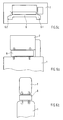
- Figure 5a to c shows a further embodiment.
- Wide air vents 6 are 2 further air vents to the side of the headrest 6.1 and 6.2 arranged to target air to the head area of the seat to direct seated passengers. Accordingly, these air vents have 6.1 and 6.2 also slats for guiding the air.
- the air vent 6 can be a configuration according to FIGS. 3 or 4.
- Corresponding adjustment wheels are located on the side of the air intake housing 6 or above the housing of the air vents 6.1 and 6.2.
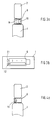
- FIGS. 6 to 8 Various fastening options are shown in the following FIGS. 6 to 8 for the air vents 6 on the seat back 1 and the headrest 2 presented.
- the basic idea here is that if the wind deflector 3 is not installed, the entire Heating device 4 with fan 5 and the air vents 6 with the connecting line 7 is removed from the vehicle. Accordingly, the air vent 6 to be attached to the seat back 1 and the headrest 2.
- a first option which is not shown, is for a height-adjustable one Headrest the air vent 6 between the headrest and the Pinch the seat back.
- locking pins be provided in the corresponding receiving openings in the seat back and snap into the headrest.
- FIG. 7a, b An arrangement for a height-adjustable headrest is shown in FIG. 7a, b the air vent 6 is attached to the headrest 2. Between the air vent 6 and the upper edge of the backrest 1, a spacer 15 is provided, to bridge the gap.
- the air vent 6 consists of a elastically deformable material, the dimensions of which are larger than the gap between the headrest 2 and the upper edge of the seat back 1. Accordingly the housing of the air vent 6 can be clamped in this gap and deform elastically according to the column size. Here you can height adjustments of the headrest can also be compensated.
- FIG. 9 shows another alternative of the invention.
- the air vents are integrated into the seat back 1 and has, for example, arranged on the upper edge of the seat back, retractable designed air vents.
- This entry opening is preferably arranged sunk and can by a not shown
- the flap must be closed when there is no wind deflector in the vehicle is.
- the connecting line 7 is made of an elastic material to ensure that all movements of the seat and the backrest can be joined without the connecting tube slipped at its junctions.
Landscapes
- Engineering & Computer Science (AREA)
- Mechanical Engineering (AREA)
- Chair Legs, Seat Parts, And Backrests (AREA)
- Body Structure For Vehicles (AREA)
Abstract
Description
- Figur 1a - c
- Eine erste Ausführungsform der Erfindung in Seiten-, Drauf- und Frontansicht;
- Figur 2
- eine erste Alternative der Erfindung;
- Figur 3a, b
- eine erste Ausgestaltung der Luftausströmer in Seiten- und Draufsicht;
- Figur 4a, b
- eine Seitenansicht und eine Draufsicht einer zweiten Ausgestaltung der Luftausströmer;
- Figur 5a - c
- eine dritte Ausgestaltung der Luftausströmer in Seiten-, Drauf- und Vorderansicht;
- Figur 6a, b
- eine erste Ausgestaltung der Befestigung der Luftausströmer;
- Figur 7a, b
- eine zweite Ausgestaltung der Befestigungsanordnung für Luftausströmer;
- Figur 8
- eine dritte Ausgestaltung der Befestigung für Luftauströmer;
- Figur 9
- eine Seitenansicht einer weiteren Ausgestaltung.
Claims (13)
- Windschott-Anordnung für offene Kraftfahrzeuge, wie Roadster oder Cabriolet, deren in einer Fahrgastzelle aufgenommene, nebeneinander angeordnete Fahrzeugsitze für Fahrer und Beifahrer jeweils eine Rückenlehne mit Kopfstütze aufweisen, wobei die Windschott-Anordnung aus einem im wesentlichen vertikal ausgerichteten, den Kopfstützenbereich hinter den Fahrzeugsitzen für Fahrer und Beifahrer überdeckenden ersten Netz und aus einem im wesentlichen horizontal ausgerichteten, den Raum zwischen dem ersten Netz und der Rückwand der Fahrgastzelle abdeckenden zweiten Netz besteht, mit einer an dem Windschott angeordneten Heizeinrichtung mit Gebläse, deren Luftaustrittsöffnung in den Nacken-/Kopfbereich der vor dem Windschott sitzenden Personen gerichtet ist,
dadurch gekennzeichnet, dass die Luftaustrittsöffnung (Luftausströmer 6) an jedem vor dem Windschott gelegenen Fahrzeugsitz direkt angeordnet ist. - Windschott-Anordnung nach Anspruch 1,
dadurch gekennzeichnet, dass der Luftausströmer zwischen Rückenlehnen-Oberkante und Unterkante der zugehörigen Kopfstütze (2) angeordnet ist. - Windschott-Anordnung nach Anspruch 1 oder 2,
dadurch gekennzeichnet, dass der Luftausströmer (6) mit Luftleiteinrichtungen (Lamellen 9, 10) versehen ist. - Windschott-Anordnung mit einem einseitig an denen Rückenlehnen gehaltenen Kopfstützen nach einem der vorangegangenen Ansprüche,
dadurch gekennzeichnet, dass der Luftausströmer (6) seitlich angeordnete Bedienelemente (Verstelleinrichtung 11, 12) für die Einstellung der Luftleiteinrichtung aufweist. - Windschott-Anordnung nach einem der vorangegangenen Ansprüche,
dadurch gekennzeichnet, dass die Luftleiteinrichtung aus einem Schwenkkopf (13) mit Horizontal-Lamellen besteht. - Windschott-Anordnung nach einem der vorangegangenen Ansprüche,
dadurch gekennzeichnet, dass der Luftausströmer (6) aus einem horizontal verlaufenden ersten Luftausströmer (6) und mindestens einem vertikal verlaufenden zweiten Luftausströmer (6.1, 6.2) besteht. - Windschott-Anordnung nach einem der vorangegangenen Ansprüche,
dadurch gekennzeichnet, dass der Luftausströmer (6) in der Oberkante der Rückenlehne (1) integriert ist. - Windschott-Anordnung nach einem der vorangegangenen Ansprüche,
dadurch gekennzeichnet, dass die Verbindungsleitung (7) zwischen dem Luftausströmer (6) und der Heizeinrichtung aus flexiblem Material besteht. - Windschott-Anordnung nach einem der vorangegangenen Ansprüche,
dadurch gekennzeichnet, dass die Verbindungsleitung (7) an der Rückenlehne (1) arretierbar ist. - Windschott-Anordnung mit einer auskragend befestigten Kopfstütze an der Rückenlehne nach einem der vorangegangenen Ansprüche,
dadurch gekennzeichnet, dass der Luftausströmer in dem Freiraum zwischen der Kopfstütze (2) und der Oberkante der Rückenlehne (1) eingeklemmt ist. - Windschott-Anordnung nach einem der vorangegangenen Ansprüche,
dadurch gekennzeichnet, dass an der Kopfstütze (2) und an der Oberkante der Rückenlehne (1) Halteelemente für den Luftausströmer (6) vorgesehen sind. - Windschott-Anordnung mit einer höhenverstellbaren Kopfstütze nach einem der vorangegangenen Ansprüche,
dadurch gekennzeichnet, dass der Luftausströmer (6) an der Kopfstütze (2) befestigt ist. - Windschott-Anordnung nach einem der vorangegangenen Ansprüche,
dadurch gekennzeichnet, dass zwischen der Unterkante des Luftausströmers (6) und der Oberkante der Rückenlehne (1) den Abstand verschließende Distanzelemente vorgesehen sind.
Applications Claiming Priority (2)
| Application Number | Priority Date | Filing Date | Title |
|---|---|---|---|
| DE10061027 | 2000-12-08 | ||
| DE2000161027 DE10061027A1 (de) | 2000-12-08 | 2000-12-08 | Windschott-Anordnung für offene Kraftfahrzeuge |
Publications (3)
| Publication Number | Publication Date |
|---|---|
| EP1213171A2 true EP1213171A2 (de) | 2002-06-12 |
| EP1213171A3 EP1213171A3 (de) | 2003-05-28 |
| EP1213171B1 EP1213171B1 (de) | 2006-10-18 |
Family
ID=7666260
Family Applications (1)
| Application Number | Title | Priority Date | Filing Date |
|---|---|---|---|
| EP20010126258 Expired - Lifetime EP1213171B1 (de) | 2000-12-08 | 2001-11-06 | Windschott-Anordnung für offene Kraftfahrzeuge |
Country Status (2)
| Country | Link |
|---|---|
| EP (1) | EP1213171B1 (de) |
| DE (2) | DE10061027A1 (de) |
Cited By (3)
| Publication number | Priority date | Publication date | Assignee | Title |
|---|---|---|---|---|
| EP1323574A3 (de) * | 2001-12-21 | 2004-06-16 | DaimlerChrysler AG | Kraftfahrzeugsitz |
| JP2007519563A (ja) * | 2004-01-29 | 2007-07-19 | ダイムラークライスラー・アクチェンゲゼルシャフト | 車両シート |
| WO2018049159A1 (en) * | 2016-09-09 | 2018-03-15 | Gentherm Inc. | Vehicle zonal microclimate system |
Families Citing this family (3)
| Publication number | Priority date | Publication date | Assignee | Title |
|---|---|---|---|---|
| DE102008010219A1 (de) * | 2008-02-20 | 2009-09-03 | Daimler Ag | Windschott mit Heizfunktion |
| US8220869B2 (en) | 2009-10-30 | 2012-07-17 | Ford Global Technologies, Llc | Temperature-and-humidity-controlled head restraint |
| DE202013005877U1 (de) | 2013-06-28 | 2013-08-08 | Johannes Haslach | Heizvorrichtung für Cabriolets |
Citations (2)
| Publication number | Priority date | Publication date | Assignee | Title |
|---|---|---|---|---|
| DE19908499C1 (de) | 1999-02-26 | 2000-04-20 | Daimler Chrysler Ag | Windschottanordnung |
| DE19908500C1 (de) | 1999-02-26 | 2000-04-27 | Daimler Chrysler Ag | Zusatzheizung für offene Fahrzeuge |
Family Cites Families (8)
| Publication number | Priority date | Publication date | Assignee | Title |
|---|---|---|---|---|
| FR2630056B1 (fr) * | 1988-04-15 | 1992-03-06 | Renault | Siege ventile de vehicule |
| DE3925809A1 (de) * | 1989-08-04 | 1991-02-07 | Bayerische Motoren Werke Ag | Personenkraftwagen in cabrioletbauweise |
| JP3301109B2 (ja) * | 1991-11-14 | 2002-07-15 | 株式会社デンソー | 座席用空調装置 |
| DE9201474U1 (de) * | 1992-02-06 | 1992-04-16 | Oris-Metallbau KG Hans Riehle, 7141 Möglingen | Zugluftabweiser bei Kraftwagen, insbesondere bei Cabrios |
| DE19810865B4 (de) * | 1998-03-13 | 2004-08-05 | Audi Ag | Cabriolet mit einem Windschott |
| DE19908497C2 (de) * | 1999-02-26 | 2003-03-13 | Daimler Chrysler Ag | Offenes Kraftfahrzeug |
| DE19908502C1 (de) * | 1999-02-26 | 2000-05-04 | Daimler Chrysler Ag | Offenes Kraftfahrzeug |
| DE19949935C1 (de) * | 1999-10-16 | 2000-11-09 | Daimler Chrysler Ag | Kopfstütze für einen Fahrzeugsitz |
-
2000
- 2000-12-08 DE DE2000161027 patent/DE10061027A1/de not_active Withdrawn
-
2001
- 2001-11-06 DE DE50111265T patent/DE50111265D1/de not_active Expired - Lifetime
- 2001-11-06 EP EP20010126258 patent/EP1213171B1/de not_active Expired - Lifetime
Patent Citations (2)
| Publication number | Priority date | Publication date | Assignee | Title |
|---|---|---|---|---|
| DE19908499C1 (de) | 1999-02-26 | 2000-04-20 | Daimler Chrysler Ag | Windschottanordnung |
| DE19908500C1 (de) | 1999-02-26 | 2000-04-27 | Daimler Chrysler Ag | Zusatzheizung für offene Fahrzeuge |
Cited By (5)
| Publication number | Priority date | Publication date | Assignee | Title |
|---|---|---|---|---|
| EP1323574A3 (de) * | 2001-12-21 | 2004-06-16 | DaimlerChrysler AG | Kraftfahrzeugsitz |
| JP2007519563A (ja) * | 2004-01-29 | 2007-07-19 | ダイムラークライスラー・アクチェンゲゼルシャフト | 車両シート |
| WO2018049159A1 (en) * | 2016-09-09 | 2018-03-15 | Gentherm Inc. | Vehicle zonal microclimate system |
| CN109689429A (zh) * | 2016-09-09 | 2019-04-26 | 金瑟姆股份有限公司 | 车辆区域微气候系统 |
| CN109689429B (zh) * | 2016-09-09 | 2022-02-22 | 金瑟姆股份有限公司 | 车辆区域微气候系统 |
Also Published As
| Publication number | Publication date |
|---|---|
| EP1213171B1 (de) | 2006-10-18 |
| EP1213171A3 (de) | 2003-05-28 |
| DE10061027A1 (de) | 2002-06-13 |
| DE50111265D1 (de) | 2006-11-30 |
Similar Documents
| Publication | Publication Date | Title |
|---|---|---|
| EP1193095B1 (de) | Windschutzeinrichtung für einen offenen Kraftwagen | |
| DE102004004387B4 (de) | Fahrzeugsitz | |
| DE10054008A1 (de) | Kraftwagensitz | |
| DE19908497C2 (de) | Offenes Kraftfahrzeug | |
| DE19908502C1 (de) | Offenes Kraftfahrzeug | |
| EP0761484A1 (de) | Windschott für ein Cabriolet | |
| DE19545405A1 (de) | Windschott für ein Cabriolet | |
| WO2004091967A2 (de) | Luftversorgungseinrichtung für einen kraftwagensitz | |
| EP1502810A2 (de) | Sitzanordnung für Fahrzeuge | |
| DE3235148A1 (de) | Windabweiser fuer kraftfahrzeuge | |
| DE102009052683A1 (de) | Fahrzeugsitz mit einer Luftversorgungseinrichtung | |
| DE10039791B4 (de) | Cabriolet | |
| EP1213171B1 (de) | Windschott-Anordnung für offene Kraftfahrzeuge | |
| DE3935630C2 (de) | Cabriolet mit einem Windschutz | |
| DE19923188C2 (de) | Fahrzeuge, insbesondere Personenkraftwagen | |
| EP1634748B1 (de) | Dachsystem für ein Kraftfahrzeug mit wenigstens zwei festen Dachteilen | |
| DE19854537B4 (de) | Belüftungsvorrichtung für Fahrzeuge | |
| DE102020101563B4 (de) | Cabriolet-Fahrzeug | |
| DE19810865B4 (de) | Cabriolet mit einem Windschott | |
| EP3681758B1 (de) | Belüftungsvorrichtung für ein fahrzeug | |
| EP3898301B1 (de) | Innenraumeinrichtung für ein kraftfahrzeug | |
| DE102010054411A1 (de) | Windschutzeinrichtung für eine Sitzanlage | |
| DE102008052019A1 (de) | Luftversorgungseinrichtung für einen Fahrzeugsitz | |
| WO2021122021A1 (de) | Belüftungsvorrichtung, verfahren und fahrzeug | |
| DE102004062498A1 (de) | Luftdüse in der Kopfstütze eines Kraftwagensitzes |
Legal Events
| Date | Code | Title | Description |
|---|---|---|---|
| PUAI | Public reference made under article 153(3) epc to a published international application that has entered the european phase |
Free format text: ORIGINAL CODE: 0009012 |
|
| AK | Designated contracting states |
Kind code of ref document: A2 Designated state(s): AT BE CH CY DE DK ES FI FR GB GR IE IT LI LU MC NL PT SE TR |
|
| AX | Request for extension of the european patent |
Free format text: AL;LT;LV;MK;RO;SI |
|
| PUAL | Search report despatched |
Free format text: ORIGINAL CODE: 0009013 |
|
| AK | Designated contracting states |
Designated state(s): AT BE CH CY DE DK ES FI FR GB GR IE IT LI LU MC NL PT SE TR |
|
| AX | Request for extension of the european patent |
Extension state: AL LT LV MK RO SI |
|
| RIC1 | Information provided on ipc code assigned before grant |
Ipc: 7B 60J 7/22 A Ipc: 7B 60H 1/24 B |
|
| 17P | Request for examination filed |
Effective date: 20030607 |
|
| AKX | Designation fees paid |
Designated state(s): DE FR GB IT |
|
| GRAP | Despatch of communication of intention to grant a patent |
Free format text: ORIGINAL CODE: EPIDOSNIGR1 |
|
| GRAS | Grant fee paid |
Free format text: ORIGINAL CODE: EPIDOSNIGR3 |
|
| GRAA | (expected) grant |
Free format text: ORIGINAL CODE: 0009210 |
|
| AK | Designated contracting states |
Kind code of ref document: B1 Designated state(s): DE FR GB IT |
|
| REG | Reference to a national code |
Ref country code: GB Ref legal event code: FG4D Free format text: NOT ENGLISH |
|
| GBT | Gb: translation of ep patent filed (gb section 77(6)(a)/1977) |
Effective date: 20061102 |
|
| REF | Corresponds to: |
Ref document number: 50111265 Country of ref document: DE Date of ref document: 20061130 Kind code of ref document: P |
|
| ET | Fr: translation filed | ||
| PLBI | Opposition filed |
Free format text: ORIGINAL CODE: 0009260 |
|
| PLAX | Notice of opposition and request to file observation + time limit sent |
Free format text: ORIGINAL CODE: EPIDOSNOBS2 |
|
| 26 | Opposition filed |
Opponent name: DAIMLERCHRYSLER AG Effective date: 20070718 |
|
| PLBB | Reply of patent proprietor to notice(s) of opposition received |
Free format text: ORIGINAL CODE: EPIDOSNOBS3 |
|
| RDAF | Communication despatched that patent is revoked |
Free format text: ORIGINAL CODE: EPIDOSNREV1 |
|
| APBM | Appeal reference recorded |
Free format text: ORIGINAL CODE: EPIDOSNREFNO |
|
| APBP | Date of receipt of notice of appeal recorded |
Free format text: ORIGINAL CODE: EPIDOSNNOA2O |
|
| APAH | Appeal reference modified |
Free format text: ORIGINAL CODE: EPIDOSCREFNO |
|
| APBQ | Date of receipt of statement of grounds of appeal recorded |
Free format text: ORIGINAL CODE: EPIDOSNNOA3O |
|
| PLAB | Opposition data, opponent's data or that of the opponent's representative modified |
Free format text: ORIGINAL CODE: 0009299OPPO |
|
| R26 | Opposition filed (corrected) |
Opponent name: DAIMLER AG Effective date: 20070718 |
|
| APBU | Appeal procedure closed |
Free format text: ORIGINAL CODE: EPIDOSNNOA9O |
|
| PLCK | Communication despatched that opposition was rejected |
Free format text: ORIGINAL CODE: EPIDOSNREJ1 |
|
| PLBN | Opposition rejected |
Free format text: ORIGINAL CODE: 0009273 |
|
| STAA | Information on the status of an ep patent application or granted ep patent |
Free format text: STATUS: OPPOSITION REJECTED |
|
| 27O | Opposition rejected |
Effective date: 20130911 |
|
| REG | Reference to a national code |
Ref country code: DE Ref legal event code: R100 Ref document number: 50111265 Country of ref document: DE Effective date: 20130911 |
|
| REG | Reference to a national code |
Ref country code: FR Ref legal event code: PLFP Year of fee payment: 15 |
|
| REG | Reference to a national code |
Ref country code: FR Ref legal event code: PLFP Year of fee payment: 16 |
|
| REG | Reference to a national code |
Ref country code: FR Ref legal event code: PLFP Year of fee payment: 17 |
|
| PGFP | Annual fee paid to national office [announced via postgrant information from national office to epo] |
Ref country code: IT Payment date: 20201130 Year of fee payment: 20 Ref country code: FR Payment date: 20201119 Year of fee payment: 20 Ref country code: DE Payment date: 20201126 Year of fee payment: 20 Ref country code: GB Payment date: 20201123 Year of fee payment: 20 |
|
| REG | Reference to a national code |
Ref country code: DE Ref legal event code: R071 Ref document number: 50111265 Country of ref document: DE |
|
| REG | Reference to a national code |
Ref country code: GB Ref legal event code: PE20 Expiry date: 20211105 |
|
| PG25 | Lapsed in a contracting state [announced via postgrant information from national office to epo] |
Ref country code: GB Free format text: LAPSE BECAUSE OF EXPIRATION OF PROTECTION Effective date: 20211105 |
|
| P01 | Opt-out of the competence of the unified patent court (upc) registered |
Effective date: 20230523 |