EP1213183B1 - Rückblickspiegel und Befestigungssystem - Google Patents
Rückblickspiegel und Befestigungssystem Download PDFInfo
- Publication number
- EP1213183B1 EP1213183B1 EP20010403163 EP01403163A EP1213183B1 EP 1213183 B1 EP1213183 B1 EP 1213183B1 EP 20010403163 EP20010403163 EP 20010403163 EP 01403163 A EP01403163 A EP 01403163A EP 1213183 B1 EP1213183 B1 EP 1213183B1
- Authority
- EP
- European Patent Office
- Prior art keywords
- obstruction
- fastening
- bodywork
- vehicle
- base
- Prior art date
- Legal status (The legal status is an assumption and is not a legal conclusion. Google has not performed a legal analysis and makes no representation as to the accuracy of the status listed.)
- Expired - Lifetime
Links
- 230000002035 prolonged effect Effects 0.000 claims 1
- 230000000903 blocking effect Effects 0.000 description 2
- 230000002787 reinforcement Effects 0.000 description 2
- 240000008042 Zea mays Species 0.000 description 1
- 238000004026 adhesive bonding Methods 0.000 description 1
- 238000002788 crimping Methods 0.000 description 1
- 238000009434 installation Methods 0.000 description 1
- 238000012423 maintenance Methods 0.000 description 1
- 238000003466 welding Methods 0.000 description 1
Images

Classifications
-
- B—PERFORMING OPERATIONS; TRANSPORTING
- B60—VEHICLES IN GENERAL
- B60R—VEHICLES, VEHICLE FITTINGS, OR VEHICLE PARTS, NOT OTHERWISE PROVIDED FOR
- B60R1/00—Optical viewing arrangements; Real-time viewing arrangements for drivers or passengers using optical image capturing systems, e.g. cameras or video systems specially adapted for use in or on vehicles
- B60R1/02—Rear-view mirror arrangements
- B60R1/06—Rear-view mirror arrangements mounted on vehicle exterior
Definitions
- the invention relates to an exterior mirror for a vehicle, and in particular its system fixation.
- An exterior mirror has usually a base which is attached to a bodywork component such as a door motor vehicle. To prevent the rear view mirror can be dismantled from the outside, the attachment is generally only accessible by inside the vehicle. These are for example screws fasteners that pass through the door to be screwed into the base.
- the vehicle assembly ranges do not do not always allow access to the means of fixing from the inside.
- a first solution is to fix the mirror with screws passing through the trim. This solution is not acceptable for reasons appearance of the vehicle.
- a second solution is to fix the mirror from the outside by means tamper evident, such as tamperproof screws. However, it is then impossible to disassemble the mirror for maintenance purposes.
- the invention has for object a mirror mounting system exterior on a separating body element inside the outside of a vehicle the rear view mirror comprising a base on which is fixed in a non-separable manner a retractable shell, the base comprising fixing means removable to fix the base on the element bodywork, the fixing means comprising operating elements, characterized in that the operating elements can be operated from the exterior of the vehicle, an operating element of at least one fixing means being at the bottom of a well, a wall of the well comprising a lateral orifice, means of obstruction being insertable into the well in front of the operating element through the lateral opening of so that the means of obstruction obstruct the at least partially the well to prevent access to the operating element, means for holding the obstruction means being arranged so as to be accessible only from inside the vehicle.
- the mirror is not removable from the outside.
- the means of attachment can only be accessed and operated by the exterior of the bodywork element and in the axis of Wells.
- To disassemble the mirror it is necessary to dismantle the means beforehand obstructing access to means of fixation. However, this is only done inside the vehicle.
- the means of obstruction are accessible to anytime by anyone who has access to the interior of the vehicle.
- the fixing means are not visible from the inside or on the trim.
- the element of bodywork has an edge accessible neither by inside or outside when the vehicle is closed, the means of obstruction being place from the edge of the bodywork element. So the means of obstruction are hidden from view when the door is closed.
- the mirror comprises a retractable shell which covers the means of fixation.
- the fixing means are visible by retracting the retractable shell and are hidden when the hull is not retracted.
- the fixing means are at least one screw which comprises a head as an operating element and which is screwed in at least one nut fixed on the element of body.
- the means obstructors have a screwed obstruction screw on the bodywork element by a threaded part, and extended by an obstruction rod passing through the lateral opening in front of the fixing means.
- the blockage rod prevents tool from accessing to the fixing means.
- the threaded part ensures the upkeep.
- the element of bodywork is a door.
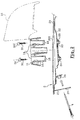
- a mirror 1 according to the invention in substantially horizontal section in Figure 1, is fixed on a door 2. It has a base 11, a retractable shell 12 mounted on the base, a mirror 17 mounted in an adjustable manner in orientation in the retractable shell 12, and a hubcap 13 arranged around the base 11.
- the door 2 has an outer panel 20, a frame 22, a substantially vertical edge 21 located towards the front of the door.
- Panel 20 has an opening 201 to reveal the frame 22.
- the frame 22 has on the side inside and near opening 201 a reinforcement 23 fixed for example by gluing.
- Base 11 is arranged through the opening 201 on the frame 22.
- the base 11 comprises two wells 14 open towards outside the door.
- the background of each of said well 14 has an orifice 16, of diameter lower than that of the well.
- Two fixing screws 30, 31 with cylindrical head 32, 33 are housed in the orifices 16 and are supported on the bottom of the wells 14.
- the fixing screws 30, 31 are screwed into nuts 24, 25 fixed on the reinforcement 23 of the frame 22 for example by welding or crimping.
- the heads 32, 33 comprise an imprint, not shown, for example hexagonal hollow, so that the fixing screws can be operated by a tool in the well.
- the frame 22 includes a fixed nut 26, for crimped example, in which a blocking screw 4 is screwed.
- the obstructing screw 4 has a threaded part 41, an obstruction rod 40 which extends the threaded part 41 to the vicinity immediate of the axis of one of the fixing screws 30, on the side of the head 32 of the fixing screw 30.
- the obstruction rod 40 passes through the wall of the well 14 through a side hole 18.
- the obstruction screw 4 is accessible to be turned through a hole 27 provided in song 21 before the door 2. This hole 27 is closed by a removable plug 5.
- the base 11 includes a passage orifice 15 in which mechanical or electrical controls of the mirror pass, in a manner known per se.
- the retractable shell 12 For mounting the mirror, as shown Figure 2, the retractable shell 12 is placed so that it frees access to wells 14 of the base 11.
- the base 11 is arranged through the opening 201 on the frame 22 then fixed by the two fixing screws 30, 31, the screws being operated by a tool in the axis of the wells.
- Shell retractable 12 can then be put back in its normal position, as shown in figure 1.
- the screw obstruction 4 is screwed and tightened in the nut fixed 26.
- the cap 5 is placed on the orifice 27.
- the obstruction rod 40 prevents access to the head 32 of the screw 30. It is then impossible to loosen the fixing screw 30 and dismantle the mirror 1 as long as the blocking screw 4 is in square.
- the screw obstruction 4 is not accessible from the outside of the vehicle.
- the invention is not limited to the example which has just been described.
- the number of fixing screws is not limited. However, it only takes one obstruction screw.
- the fixing means can be a loose nut screwed onto a fixed threaded rod on the bodywork element.
- the screw obstruction can be fixed on an element of the base.
- the mirror can be fixed on one wing, the obstruction screw passing through the sleeping from the door.
Landscapes
- Engineering & Computer Science (AREA)
- Multimedia (AREA)
- Mechanical Engineering (AREA)
- Rear-View Mirror Devices That Are Mounted On The Exterior Of The Vehicle (AREA)
Claims (6)
- Befestigungssystem eines äußeren Rückblickspiegels (1) an einem Element der Karosserie (2), welches das Innere von dem Äußeren eines Fahrzeuges trennt, wobei der Rückblickspiegel (1) eine Basis (11) aufweist, an welcher auf nicht trennbare Art und Weise eine einklappbare Schale (12) befestigt ist, wobei die Basis (11) demontierbare Mittel (30, 31) zum Befestigen der Basis (11) an dem Element der Karosserie (2) aufweist, wobei die Befestigungsmittel (30, 31) Betätigungselemente (32, 33) aufweisen, dadurch gekennzeichnet, dass die Betätigungselemente (32, 33) von der Außenseite des Fahrzeugs betätigbar sind, wobei mindestens ein Betätigungselement (32) von mindestens einem Befestigungsmittel am Boden eines Schachtes (14) ist, wobei eine Wand des Schachtes (14) eine seitliche Öffnung (18) aufweist, wobei Versperrungsmittel (4) in den Schacht (14) vor dem Betätigungselement (32) durch die seitliche Öffnung (18) auf solch eine Art und Weise einführbar sind, dass die Versperrungsmittel (4) mindestens teilweise den Schacht (14) verschließen, um den Zugang zu dem Betätigungselement (32) zu verhindern, wobei Haltemittel (41) der Verschließungsmittel (4) in einer Art und Weise angeordnet sind, dass sie ausschließlich vom Inneren des Fahrzeuges zugänglich sind.
- Befestigungssystem gemäß Anspruch 1, dadurch gekennzeichnet, dass das Element der Karosserie (2) eine Schmalseite (21) aufweist, die weder von innen noch von außen zugänglich ist, wenn das Fahrzeug verschlossen ist, wobei die Verschließungsmittel (4) ausgehend von der Schmalseite (21) des Karosserieelements (2) eingesetzt werden.
- Befestigungssystem gemäß Anspruch 1, dadurch gekennzeichnet, dass die einklappbare Schale (12) die Befestigungsmittel (30, 31) abdeckt.
- Befestigungssystem gemäß Anspruch 1, dadurch gekennzeichnet, dass die Befestigungsmittel mindestens eine Schraube (30, 31) sind, welche einen Kopf (32, 33) als Betätigungselement aufweist, und welche in mindestens eine Mutter (24, 25), die an dem Element der Karosserie (2) befestigt ist, eingeschraubt ist.
- Befestigungssystem gemäß Anspruch 1, dadurch gekennzeichnet, dass die Verschließungsmittel eine Verschließungsschraube (4) aufweisen, welche an dem Element der Karosserie (2) durch einen mit einem Gewinde versehenen Teil (41) eingeschraubt ist, und welche durch eine Verschließungsstange (40) verlängert ist, die durch die seitliche Öffnung (18) vor den Befestigungsmitteln (30) hindurchgeht.
- Befestigungssystem gemäß Anspruch 1, dadurch gekennzeichnet, dass das Element der Karosserie eine Fahrzeugtür (2) ist.
Applications Claiming Priority (2)
| Application Number | Priority Date | Filing Date | Title |
|---|---|---|---|
| FR0015854 | 2000-12-07 | ||
| FR0015854A FR2817814B1 (fr) | 2000-12-07 | 2000-12-07 | Retroviseur exterieur et systeme de fixation |
Publications (2)
| Publication Number | Publication Date |
|---|---|
| EP1213183A1 EP1213183A1 (de) | 2002-06-12 |
| EP1213183B1 true EP1213183B1 (de) | 2004-09-22 |
Family
ID=8857330
Family Applications (1)
| Application Number | Title | Priority Date | Filing Date |
|---|---|---|---|
| EP20010403163 Expired - Lifetime EP1213183B1 (de) | 2000-12-07 | 2001-12-07 | Rückblickspiegel und Befestigungssystem |
Country Status (3)
| Country | Link |
|---|---|
| EP (1) | EP1213183B1 (de) |
| DE (1) | DE60105743T2 (de) |
| FR (1) | FR2817814B1 (de) |
Cited By (1)
| Publication number | Priority date | Publication date | Assignee | Title |
|---|---|---|---|---|
| AU2007322722B2 (en) * | 2006-11-21 | 2011-10-06 | Isuzu Motors Limited | Vehicle door structure |
Families Citing this family (8)
| Publication number | Priority date | Publication date | Assignee | Title |
|---|---|---|---|---|
| FR2878481B1 (fr) | 2004-11-30 | 2007-02-23 | Peugeot Citroen Automobiles Sa | Dispositif de fixation d'un retroviseur exterieur sur un element de carrosserie d'un vehicule et agencement d'un retroviseur exterieur sur un element de carrosserie d'un vehicule |
| DE102006040987B4 (de) * | 2006-08-31 | 2016-07-14 | Audi Ag | Vorrichtung zur Anbringung eines Außenspiegels |
| DE102007056671B4 (de) | 2007-11-24 | 2019-03-14 | Dr. Ing. H.C. F. Porsche Aktiengesellschaft | Befestigungsanordnung |
| US7699285B2 (en) * | 2008-03-05 | 2010-04-20 | Ford Global Technologies | Automotive mirror mounting system |
| DE102009019903B4 (de) * | 2009-05-07 | 2024-01-11 | Volkswagen Ag | Befestigungsanordnung für einen Türaußenspiegel und Verfahren zur Herstellung einer Verbindung eines Türaußenspiegels mit einer Fahrzeugtür |
| FR2965522A1 (fr) * | 2010-09-30 | 2012-04-06 | Peugeot Citroen Automobiles Sa | Systeme de fixation d'un retroviseur de vehicule |
| DE202014010295U1 (de) | 2014-03-28 | 2015-04-01 | Dr. Ing. H.C. F. Porsche Aktiengesellschaft | Anordnung einer Kraftfahrzeugtür und eines mit dieser verbundenen Außenrückblickspiegels |
| DE102015105913A1 (de) * | 2015-04-17 | 2016-10-20 | Dr. Ing. H.C. F. Porsche Aktiengesellschaft | Kraftfahrzeugtür mit einem Außenrückspiegel |
Family Cites Families (5)
| Publication number | Priority date | Publication date | Assignee | Title |
|---|---|---|---|---|
| US2516939A (en) * | 1947-08-16 | 1950-08-01 | Accessory Res Corp | Rear vision mirror |
| US2495123A (en) * | 1947-10-25 | 1950-01-17 | Charles E Morley | Fastening device |
| DE2320056C2 (de) * | 1973-04-19 | 1985-08-01 | Engelmann, Joachim, 3002 Wedemark | Vorrichtung zum Befestigen von Kraftfahrzeugrückblickspiegeln |
| DE2852555C2 (de) * | 1978-12-05 | 1983-12-01 | Peter 8021 Baierbrunn Ferstl | Halterung, insbesondere für einen Kraftfahrzeug-Rückblickspiegel |
| DE3510780C1 (de) * | 1985-03-25 | 1986-05-22 | Audi AG, 8070 Ingolstadt | Fahrzeugtüre mit einem Außenspiegel |
-
2000
- 2000-12-07 FR FR0015854A patent/FR2817814B1/fr not_active Expired - Fee Related
-
2001
- 2001-12-07 EP EP20010403163 patent/EP1213183B1/de not_active Expired - Lifetime
- 2001-12-07 DE DE2001605743 patent/DE60105743T2/de not_active Expired - Lifetime
Cited By (1)
| Publication number | Priority date | Publication date | Assignee | Title |
|---|---|---|---|---|
| AU2007322722B2 (en) * | 2006-11-21 | 2011-10-06 | Isuzu Motors Limited | Vehicle door structure |
Also Published As
| Publication number | Publication date |
|---|---|
| DE60105743D1 (de) | 2004-10-28 |
| DE60105743T2 (de) | 2005-05-12 |
| EP1213183A1 (de) | 2002-06-12 |
| FR2817814B1 (fr) | 2003-01-24 |
| FR2817814A1 (fr) | 2002-06-14 |
Similar Documents
| Publication | Publication Date | Title |
|---|---|---|
| EP1213183B1 (de) | Rückblickspiegel und Befestigungssystem | |
| EP0281442B1 (de) | Einstellvorrichtung des Winkelstandes eines Lenkrades auf einer Fahrzeuglenksäule | |
| FR2892993A1 (fr) | Dispositif aerodynamique pour un vehicule automobile et vehicule automobile comportant au moins un tel dispositif aerodynamique. | |
| EP1883571B1 (de) | Heckstütze für kraftfahrzeug, heckmodul und verfahren zur befestigung solch eines moduls | |
| EP0845569B1 (de) | Laufradvorrichtung für Schiebetür | |
| WO2009118491A1 (fr) | Console d'un vehicule automobile | |
| EP1043218B1 (de) | Aerodynamischer Windabweiser mit einstellbarer Neigung für Lastkraftwagen | |
| FR2749053A1 (fr) | Systeme vis-ecrou pour le reglage en position relative de deux elements mobiles l'un par rapport a l'autre, notamment pour le reglage en position d'un siege d'automobile | |
| EP3986732A1 (de) | Befestigung eines steuerungsträgers für die aussenöffnung einer kraftfahrzeugtür | |
| FR2794787A1 (fr) | Dispositif de renvoi de fouillot | |
| FR3001660A1 (fr) | Groupe motopropulseur equipant un vehicule automobile | |
| EP1867814A1 (de) | Verstellbare Verriegelungsvorrichtung für eine Fahrzeughaube | |
| EP2022921B2 (de) | Befestigungsvorrichtung für einen Mitnehmer einer Fensterscheibe bestehend aus Schraubenmuttern und Schrauben | |
| EP1361114B1 (de) | Aussenrückblickspiegel mit feststehendem Gehäuse | |
| FR2931505A3 (fr) | Agencement de moyens de verrouillage sur une porte de coffre de vehicule automobile perfectionnes | |
| FR3010040A1 (fr) | Dispositif de positionnement geometrique d'une aile avant sur la structure avant de la caisse d'un vehicule automobile | |
| FR2963917A1 (fr) | Vehicule comportant un dispositif de blocage antivol des roues directrices | |
| WO2022101560A1 (fr) | Dispositif rapportable de verrouillage pour porte arrière battante ou latérale coulissante de véhicule utilitaire | |
| FR2730672A1 (fr) | Dispositif de remorquage d'un vehicule automobile | |
| FR3144940A1 (fr) | Volet arrière de coffre doté d’un becquet « flottant » | |
| EP1396383B1 (de) | Gepäckraumabdeckung für Kraftfahrzeug | |
| FR2817136A1 (fr) | Charniere pour abattant de cuvette de water-closet | |
| FR2979289A1 (fr) | Dispositif de reglage de la position d'une vitre mobile sur une porte de vehicule automobile et porte equipee d'un tel dispositif | |
| FR2596335A1 (fr) | Siege de vehicule a ailes laterales reglables | |
| FR2809697A1 (fr) | Volet arriere de fermeture d'un coffre de vehicule automobile equipe d'un deflecteur transversal mobile |
Legal Events
| Date | Code | Title | Description |
|---|---|---|---|
| PUAI | Public reference made under article 153(3) epc to a published international application that has entered the european phase |
Free format text: ORIGINAL CODE: 0009012 |
|
| AK | Designated contracting states |
Kind code of ref document: A1 Designated state(s): AT BE CH CY DE DK ES FI FR GB GR IE IT LI LU MC NL PT SE TR |
|
| AX | Request for extension of the european patent |
Free format text: AL;LT;LV;MK;RO;SI |
|
| RAP1 | Party data changed (applicant data changed or rights of an application transferred) |
Owner name: RENAULT S.A.S. |
|
| 17P | Request for examination filed |
Effective date: 20021202 |
|
| AKX | Designation fees paid |
Designated state(s): BE DE ES GB IT |
|
| GRAP | Despatch of communication of intention to grant a patent |
Free format text: ORIGINAL CODE: EPIDOSNIGR1 |
|
| GRAS | Grant fee paid |
Free format text: ORIGINAL CODE: EPIDOSNIGR3 |
|
| GRAA | (expected) grant |
Free format text: ORIGINAL CODE: 0009210 |
|
| AK | Designated contracting states |
Kind code of ref document: B1 Designated state(s): BE DE ES GB IT |
|
| PG25 | Lapsed in a contracting state [announced via postgrant information from national office to epo] |
Ref country code: IT Free format text: LAPSE BECAUSE OF FAILURE TO SUBMIT A TRANSLATION OF THE DESCRIPTION OR TO PAY THE FEE WITHIN THE PRESCRIBED TIME-LIMIT;WARNING: LAPSES OF ITALIAN PATENTS WITH EFFECTIVE DATE BEFORE 2007 MAY HAVE OCCURRED AT ANY TIME BEFORE 2007. THE CORRECT EFFECTIVE DATE MAY BE DIFFERENT FROM THE ONE RECORDED. Effective date: 20040922 Ref country code: GB Free format text: LAPSE BECAUSE OF FAILURE TO SUBMIT A TRANSLATION OF THE DESCRIPTION OR TO PAY THE FEE WITHIN THE PRESCRIBED TIME-LIMIT Effective date: 20040922 |
|
| REG | Reference to a national code |
Ref country code: GB Ref legal event code: FG4D Free format text: NOT ENGLISH |
|
| REG | Reference to a national code |
Ref country code: IE Ref legal event code: FG4D Free format text: FRENCH |
|
| REF | Corresponds to: |
Ref document number: 60105743 Country of ref document: DE Date of ref document: 20041028 Kind code of ref document: P |
|
| PG25 | Lapsed in a contracting state [announced via postgrant information from national office to epo] |
Ref country code: ES Free format text: LAPSE BECAUSE OF FAILURE TO SUBMIT A TRANSLATION OF THE DESCRIPTION OR TO PAY THE FEE WITHIN THE PRESCRIBED TIME-LIMIT Effective date: 20050102 |
|
| GBV | Gb: ep patent (uk) treated as always having been void in accordance with gb section 77(7)/1977 [no translation filed] |
Effective date: 20040922 |
|
| REG | Reference to a national code |
Ref country code: IE Ref legal event code: FD4D |
|
| PLBE | No opposition filed within time limit |
Free format text: ORIGINAL CODE: 0009261 |
|
| STAA | Information on the status of an ep patent application or granted ep patent |
Free format text: STATUS: NO OPPOSITION FILED WITHIN TIME LIMIT |
|
| 26N | No opposition filed |
Effective date: 20050623 |
|
| PGFP | Annual fee paid to national office [announced via postgrant information from national office to epo] |
Ref country code: DE Payment date: 20141211 Year of fee payment: 14 |
|
| PGFP | Annual fee paid to national office [announced via postgrant information from national office to epo] |
Ref country code: BE Payment date: 20141219 Year of fee payment: 14 |
|
| PG25 | Lapsed in a contracting state [announced via postgrant information from national office to epo] |
Ref country code: BE Free format text: LAPSE BECAUSE OF NON-PAYMENT OF DUE FEES Effective date: 20151231 |
|
| REG | Reference to a national code |
Ref country code: DE Ref legal event code: R119 Ref document number: 60105743 Country of ref document: DE |
|
| PG25 | Lapsed in a contracting state [announced via postgrant information from national office to epo] |
Ref country code: DE Free format text: LAPSE BECAUSE OF NON-PAYMENT OF DUE FEES Effective date: 20160701 |