EP1213192A1 - Structure de support de pédale pour véhicule - Google Patents
Structure de support de pédale pour véhicule Download PDFInfo
- Publication number
- EP1213192A1 EP1213192A1 EP01129207A EP01129207A EP1213192A1 EP 1213192 A1 EP1213192 A1 EP 1213192A1 EP 01129207 A EP01129207 A EP 01129207A EP 01129207 A EP01129207 A EP 01129207A EP 1213192 A1 EP1213192 A1 EP 1213192A1
- Authority
- EP
- European Patent Office
- Prior art keywords
- pedal
- bracket
- pedal bracket
- rigidity
- brittle
- Prior art date
- Legal status (The legal status is an assumption and is not a legal conclusion. Google has not performed a legal analysis and makes no representation as to the accuracy of the status listed.)
- Granted
Links
- 230000001502 supplementing effect Effects 0.000 claims abstract description 35
- 239000011324 bead Substances 0.000 claims description 9
- 230000004048 modification Effects 0.000 abstract description 8
- 238000012986 modification Methods 0.000 abstract description 8
- 238000010521 absorption reaction Methods 0.000 abstract description 6
- 230000015572 biosynthetic process Effects 0.000 abstract description 4
- 230000008961 swelling Effects 0.000 description 8
- 239000000725 suspension Substances 0.000 description 4
- 238000010276 construction Methods 0.000 description 3
- 239000000470 constituent Substances 0.000 description 1
- 230000003247 decreasing effect Effects 0.000 description 1
- 230000000994 depressogenic effect Effects 0.000 description 1
- 238000006073 displacement reaction Methods 0.000 description 1
- 238000004519 manufacturing process Methods 0.000 description 1
- 230000001737 promoting effect Effects 0.000 description 1
- 230000002787 reinforcement Effects 0.000 description 1
Images

Classifications
-
- G—PHYSICS
- G05—CONTROLLING; REGULATING
- G05G—CONTROL DEVICES OR SYSTEMS INSOFAR AS CHARACTERISED BY MECHANICAL FEATURES ONLY
- G05G1/00—Controlling members, e.g. knobs or handles; Assemblies or arrangements thereof; Indicating position of controlling members
- G05G1/30—Controlling members actuated by foot
-
- B—PERFORMING OPERATIONS; TRANSPORTING
- B60—VEHICLES IN GENERAL
- B60T—VEHICLE BRAKE CONTROL SYSTEMS OR PARTS THEREOF; BRAKE CONTROL SYSTEMS OR PARTS THEREOF, IN GENERAL; ARRANGEMENT OF BRAKING ELEMENTS ON VEHICLES IN GENERAL; PORTABLE DEVICES FOR PREVENTING UNWANTED MOVEMENT OF VEHICLES; VEHICLE MODIFICATIONS TO FACILITATE COOLING OF BRAKES
- B60T7/00—Brake-action initiating means
- B60T7/02—Brake-action initiating means for personal initiation
- B60T7/04—Brake-action initiating means for personal initiation foot actuated
- B60T7/06—Disposition of pedal
- B60T7/065—Disposition of pedal with means to prevent injuries in case of collision
-
- G—PHYSICS
- G05—CONTROLLING; REGULATING
- G05G—CONTROL DEVICES OR SYSTEMS INSOFAR AS CHARACTERISED BY MECHANICAL FEATURES ONLY
- G05G1/00—Controlling members, e.g. knobs or handles; Assemblies or arrangements thereof; Indicating position of controlling members
- G05G1/30—Controlling members actuated by foot
- G05G1/32—Controlling members actuated by foot with means to prevent injury
-
- Y—GENERAL TAGGING OF NEW TECHNOLOGICAL DEVELOPMENTS; GENERAL TAGGING OF CROSS-SECTIONAL TECHNOLOGIES SPANNING OVER SEVERAL SECTIONS OF THE IPC; TECHNICAL SUBJECTS COVERED BY FORMER USPC CROSS-REFERENCE ART COLLECTIONS [XRACs] AND DIGESTS
- Y10—TECHNICAL SUBJECTS COVERED BY FORMER USPC
- Y10T—TECHNICAL SUBJECTS COVERED BY FORMER US CLASSIFICATION
- Y10T74/00—Machine element or mechanism
- Y10T74/20—Control lever and linkage systems
- Y10T74/20528—Foot operated
Definitions
- the present invention relates to a pedal bracket structure for a vehicle brake pedal lever or clutch pedal lever rotatably mounted on the vehicle.
- pedal bracket structure As a pedal bracket structure, various structures have been proposed and in use for a brake pedal lever or clutch pedal lever mounted and rotatably supported on a vehicle such as an automobile. In recent years, pedal bracket structures have been in demand from the viewpoint of crash safety. The pedal bracket structures can effectively prevent the deformation of the pedal toward the driver when impact is applied from front of the vehicle, in particular, in an accident involving a frontal collision.
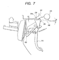
- Fig. 6 a first conventional example of a pedal bracket structure disclosed in Japanese Patent Unexamined Patent Publication No. Hei. 10-297400 is shown, which was proposed as a pedal bracket structure. When an external force that is equal to or greater than a predetermined value is applied from front of the vehicle, the pedal bracket structure can control the displacement of the pedal surface.
- a certain longitudinal buckling load is inputted into a bracket 110.
- Side plates 111, 111 of the bracket 110 extend between a bridge member 116 and a mounting member 118.
- a hole is formed in each of the side plates 111,111. Consequently, since the longitudinal rigidity of the bracket is decreased by the holes, the bracket is made to crush easily.
- a back plate 140 is provided just above the hole on the side plate 111 to be spaced away from the bridge member 116, whereby the longitudinal rigidity of the bracket is increased.
- a flange 142a is disposed on a guide groove bottom surface of the back plate 140. Then, since the flange 142a presses against a pressed portion 131 of a pedal lever 130, the pedal lever 125 swings clockwise, i.e., forward, whereby damage to the driver can be prevented.
- a second conventional example of a pedal bracket structure disclosed in Japanese Patent Unexamined Publication No. Hei. 9-254821 was proposed as a pedal bracket structure.
- the pedal bracket structure can ensure that the pedal is withdrawn forward, when energy is inputted to the front of a vehicle.
- a bracket side sliding portion 238 having an inclination angle ⁇ in regard to horizon at an upper end portion of a pedal bracket 222, and a slit 238a is formed in the bracket side sliding portion 238.
- a vehicle side sliding member 241 is fixed to an instrument panel reinforcement 243.
- a front-end portion of an inclined surface 242 and the slit 238a are fixed with a bolt 240.
- a direction in which the pedal bracket 222 is released from the bolt 240 is made to substantially coincide with the inclination angle ⁇ of the bracket side sliding portion 238 and the inclined surface 242. Since the bracket side sliding portion 238 released from the bolt 240 is withdrawn along the inclination at the angle ⁇ of the inclined surface 242, a bottom of a pedal lever 218 swings forward of the vehicle accordingly and the withdrawal thereof is restrained.
- the bracket is constructed so that the longitudinal rigidity is lowered by opening the holes to thereby be easily crushed. Therefore, the back plate 140 is provided on each of the side plate 111 just above the hole to improve the longitudinal rigidity. There may be caused a risk that the deformation promoting function so provided is deteriorated. In addition thereto, since the rigid feeling during the normal pedal operation is reduced, there may be caused a risk that the operability is deteriorated.
- the second conventional example there are involved a number of constituent components, and moreover the large modification is made to the mounting portion to the vehicle body at the rear of the bracket, this making for an increase in production costs.
- the present invention was made to cope with this.
- An object thereof is to provide a pedal bracket supporting structure that can solve the problems inherent in the conventional pedal bracket (supporting) structures.
- an object thereof is to provide high rigidity and a superior operation feeling while providing a superior capability of absorbing impact through deformation. Further, an object thereof is simple in construction.
- a pedal bracket structure wherein a pedal lever is rotatably supported in the vicinity of a rear end portion of a pedal bracket fixed to a toe board at a front end portion thereof via a pedal lever pivot, the pedal bracket structure includes a rigidity supplementing portion is formed in the vicinity of the front end portion of the pedal bracket, whereas a brittle portion is formed at a rear end side of the rigidity supplementing portion.
- the brittle portion is formed ahead of a pedal lever pivot in a longitudinal direction of the pedal bracket.
- the pedal bracket has a rigidity increasing member between the pedal lever pivot and a mounting portion relative to a vehicle body and is located at the rear of the pedal bracket is increased.
- the rigidity increasing member includes a saddle type switch bracket fastened to said pedal bracket together with the pedal lever pivot in order to increase the rigidity.
- a rigidity supplementing bracket disposed between the switch bracket and the mounting portion to the vehicle body is aligned with and fixed to the switch bracket.
- the brittle portion is formed for promotion of impact absorption by way of deformation between the mounting portion to the toe board and the brittle portion.
- Figs. 1 to 5 show an embodiment of a pedal bracket according to the present invention.
- Fig. 1A is a side view of a partially cut-away pedal bracket structure wherein a pedal lever is supported.
- Fig. 1B is a view of the pedal bracket structure as seen in a direction indicated by an arrow A of Fig. 1A.
- Fig. 2 is a perspective view of the pedal bracket.
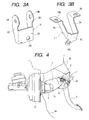
- Fig. 3A is a perspective view of a switch bracket.
- Fig. 3B is a bottom perspective view of a rigidity supplementing bracket.
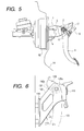
- Fig. 4 is a side view in the vicinity of a toe board showing a state in which the pedal bracket is supported.
- FIG. 5 is a side view in the vicinity of the toe board showing a state in which the pedal bracket is deformed by load applied thereto from front of the vehicle.
- a pedal lever 3 is rotatably supported in the vicinity of a rear end portion of a pedal bracket 1.
- the pedal bracket 1 is fixed to a toe board (refer to reference numeral 14 in Fig. 4) at a front end portion thereof.
- a rigidity supplementing portion 4 is formed in the vicinity of the front end portion of the toe board.
- a brittle portion 5 is formed at a rear end portion of the rigidity supplementing portion 4.
- the pedal bracket 1 provides a portal configuration, as viewed from the top, which is made to open at a rear end portion thereof.
- a pedal lever pivot 2 for rotatably supporting the pedal lever 3 is rotatably supported in left and right pivot holes 11A, 11B opened in the vicinity of rear end portions of left and right walls 1A, 1B of the pedal bracket 1.
- the pedal bracket 1 is mounted to the body of a vehicle at the rear end portion thereof with a suspension bracket 16.
- a saddle type switch bracket 6 as shown in Fig.
- a member denoted by reference numeral 8 in Fig. 1A is a coil spring wound around the pedal lever pivot 2 for returning the pedal lever 3 to its initial position.
- reference numeral 3' denotes a pedal position taken by the pedal when it is depressed.
- a rigidity supplementing bracket 7 (preferably this is also a saddle type bracket as with the switch bracket 6) is disposed between the switch bracket 6 and the mounting portion to the vehicle body.
- the switch bracket 6 and a rigidity supplementing bracket 7 are aligned with and fixed to each other at switch mounting surfaces 6C, 7C thereof.
- the rigidity supplementing bracket 7 is mounted to a lower end portion of the suspension bracket 16 with mounting bolts which are inserted into mounting holes 13A, 13B formed in upper end portions of left and right arms 7A, 7B of the rigidity supplementing bracket 7.
- a switch member 10 is passed through switch mounting holes 12C, 13C in the switch mounting surfaces 6C, 7C of the switch bracket 6 and the rigidity supplementing bracket 7 to be mounted and fixed to both of the brackets.
- the switch member 10 itself functions as a fixing tool for fixing both of the switch mounting surfaces 6C, 7C which are aligned with each other as well.
- a distal end portion of the switch member 10 is disposed within the operation range of a pressing piece 9 mounted on the pedal lever 3.
- the rigidity supplementing portion 4 adopts a swelling bead.
- the swelling bead is formed to swell outwardly from a portion in the vicinity of the front end portion of each of the left and right side walls 1A, 1B of the pedal bracket 1 through pressing.
- Semi-circular hole portions (brittle portions) 5, 5 are formed contiguously with rear ends of the swelling beads (rigidity supplementing portions) 4, 4 as the brittle portion.
- the hole portion 5 as the brittle portion is formed ahead of the pedal lever pivot 2 as viewed longitudinally.
- the swelling beads 4 as the rigidity supplementing portion are provided contiguously with the hole portions 5 as the brittle portion formed to promote the absorption of impact through deformation between the mounting portion to the toe board and the hole portions 5.
- the pedal bracket while the pedal bracket is made to deform longitudinally easily by the formation of the brittle portion, only with the simple structural modification of the swelling beads 4, the pedal bracket provides such a superior rigid feeling.
- the driver feels no uncertainty in operating the pedal, when the pedal is operated during the normal pedal operation, because the rigidity is supplemented in an ensured fashion against a force applied in the closing direction of the pedal.
- the swelling bead as the brittle portion may be provided as a curved rib or a rigid supplementing plate may be attached thereto, the brittle portion may be constituted by a number of slits or formed into a thin portion) , including the configuration of the pedal lever and mode for rotatably supporting the pedal lever on the pedal bracket, the configuration of the switch bracket and the rigid supplementing bracket and mode for aligning and fixing them together, and the mode for mounting the switch bracket and rigid supplementing bracket to the pedal bracket and the suspension bracket.
- the rigidity supplementing portion is formed in the vicinity of the aforesaid front end portion and the brittle portion is formed at the rear end portion of the rigidity supplementing portion.
- the pedal bracket provides such a superior rigid feeling that the driver feels no uncertainty in operating the pedal since the rigidity is supplemented in an ensured fashion against a force applied in the closing direction when the pedal is operated during the normal pedal operation.
- the brittle portion By forming the brittle portion ahead of the pedal lever pivot as viewed in the longitudinal direction of the vehicle body, the brittle portion effectively deforms to absorb impact ahead of the pedal lever pivot supporting portion. Therefore, the deformation in the vicinity of the pedal lever pivot supporting portion is suppressed to thereby eliminate the risk that the diver is injured.
- the rigidity supplementing bracket which is disposed between the switch bracket and the mounting portion to the vehicle body, is aligned with and fixed to the switch bracket in order to attain the high rigidity.
- the rigid feeling is ensured by the switch bracket fastened together with the pedal lever pivot at the time of normal pedal operation.
- the expansion of the open end is prevented when the bracket is deformed by the load from front of the vehicle.
- the pedal bracket structure which is high in rigidity, superior in operation feeling and simple in construction while it has the superior capability of absorbing impact through deformation.
Landscapes
- Engineering & Computer Science (AREA)
- Physics & Mathematics (AREA)
- General Physics & Mathematics (AREA)
- Automation & Control Theory (AREA)
- Transportation (AREA)
- Mechanical Engineering (AREA)
- Mechanical Control Devices (AREA)
- Body Structure For Vehicles (AREA)
- Braking Elements And Transmission Devices (AREA)
- Auxiliary Drives, Propulsion Controls, And Safety Devices (AREA)
Applications Claiming Priority (2)
| Application Number | Priority Date | Filing Date | Title |
|---|---|---|---|
| JP2000373799A JP3558982B2 (ja) | 2000-12-08 | 2000-12-08 | ペダルブラケット構造 |
| JP2000373799 | 2000-12-08 |
Publications (2)
| Publication Number | Publication Date |
|---|---|
| EP1213192A1 true EP1213192A1 (fr) | 2002-06-12 |
| EP1213192B1 EP1213192B1 (fr) | 2008-06-11 |
Family
ID=18843107
Family Applications (1)
| Application Number | Title | Priority Date | Filing Date |
|---|---|---|---|
| EP01129207A Expired - Lifetime EP1213192B1 (fr) | 2000-12-08 | 2001-12-07 | Structure de support de pédale pour véhicule |
Country Status (4)
| Country | Link |
|---|---|
| US (1) | US7011339B2 (fr) |
| EP (1) | EP1213192B1 (fr) |
| JP (1) | JP3558982B2 (fr) |
| DE (1) | DE60134380D1 (fr) |
Cited By (1)
| Publication number | Priority date | Publication date | Assignee | Title |
|---|---|---|---|---|
| DE102010025566A1 (de) * | 2010-06-29 | 2011-12-29 | Gm Global Technology Operations Llc (N.D.Ges.D. Staates Delaware) | Anordnung zum Lösen eines Fußpedals |
Families Citing this family (13)
| Publication number | Priority date | Publication date | Assignee | Title |
|---|---|---|---|---|
| JP2003025864A (ja) * | 2001-07-17 | 2003-01-29 | Nissan Motor Co Ltd | アクセルペダル装置の取付構造 |
| US6951152B2 (en) * | 2003-02-17 | 2005-10-04 | Dura Global Technologies, Inc. | Crash release arrangement and method for an automotive pedal mounting |
| JP4540302B2 (ja) * | 2003-05-21 | 2010-09-08 | 富士重工業株式会社 | 自動車用ペダル支持構造 |
| EP1512586B1 (fr) * | 2003-09-03 | 2007-01-10 | Mazda Motor Corporation | Structure de support pour un pédal automobile |
| DE602005000502T2 (de) * | 2004-09-27 | 2007-11-08 | Mazda Motor Corp. | Fahrzeugpedalabstützung |
| US20100089198A1 (en) * | 2006-12-27 | 2010-04-15 | Hiruta-Kogyo Co., Ltd. | Pedal device |
| JP5181872B2 (ja) * | 2008-06-30 | 2013-04-10 | 日産自動車株式会社 | 燃料配管保護構造 |
| US20100107804A1 (en) * | 2008-11-04 | 2010-05-06 | Tervol Stuart A | Fixed pedal assembly with multi-piece support bracket and captive pivot |
| JP5327155B2 (ja) * | 2010-07-15 | 2013-10-30 | 株式会社デンソー | ペダル装置 |
| US8550412B2 (en) * | 2010-11-08 | 2013-10-08 | Toyota Motor Engineering And Manufacturing North America, Inc. | High load resistant stop lamp switch brackets and brake pedal assemblies incorporating the same |
| KR101897351B1 (ko) * | 2016-10-21 | 2018-09-10 | 현대자동차주식회사 | 차량용 브레이크페달 장치 |
| KR102394830B1 (ko) * | 2017-06-28 | 2022-05-06 | 현대자동차주식회사 | 충격 분리 방식 페달 |
| JP7053519B2 (ja) * | 2019-02-19 | 2022-04-12 | トヨタ自動車株式会社 | 車両用ペダル装置 |
Citations (3)
| Publication number | Priority date | Publication date | Assignee | Title |
|---|---|---|---|---|
| EP0928726A2 (fr) * | 1998-01-13 | 1999-07-14 | Nissan Motor Co., Ltd. | Agencement de pédale de frein d'un véhicule |
| EP0928727A2 (fr) * | 1998-01-13 | 1999-07-14 | Nissan Motor Co., Ltd. | Assemblage d'une pédale de frein d'un véhicule |
| US6112615A (en) * | 1996-04-30 | 2000-09-05 | Toyota Jidosha Kabushiki Kaisha | Vehicle pedal supporting structure |
Family Cites Families (13)
| Publication number | Priority date | Publication date | Assignee | Title |
|---|---|---|---|---|
| DE4344386A1 (de) * | 1993-12-24 | 1995-06-29 | Opel Adam Ag | Pedalwerk für ein Fahrzeug |
| JP3267082B2 (ja) * | 1994-12-28 | 2002-03-18 | トヨタ自動車株式会社 | 車両用ペダル装置 |
| JP3267145B2 (ja) * | 1996-03-25 | 2002-03-18 | トヨタ自動車株式会社 | 車両用ペダル支持構造 |
| JP3267182B2 (ja) * | 1996-05-29 | 2002-03-18 | トヨタ自動車株式会社 | 車両用ペダル変位制御構造 |
| US6327930B1 (en) * | 1996-12-11 | 2001-12-11 | Toyota Jidosha Kabushiki Kaisha | Pedal displacement-control structure for a vehicle |
| JP3903138B2 (ja) | 1997-04-25 | 2007-04-11 | フタバ産業株式会社 | 車両用ペダル支持構造 |
| JPH10338108A (ja) * | 1997-06-09 | 1998-12-22 | Kanto Auto Works Ltd | ブレーキペダル機構 |
| JP3409651B2 (ja) | 1997-07-07 | 2003-05-26 | 日産自動車株式会社 | 自動車のペダルブラケット構造 |
| JPH1143073A (ja) | 1997-07-29 | 1999-02-16 | Toyota Motor Corp | 車両用ペダル変位制御構造 |
| JP2000095115A (ja) * | 1998-09-21 | 2000-04-04 | Suzuki Motor Corp | ステアリングハンガーブラケットの連結構造 |
| JP3932702B2 (ja) | 1998-11-25 | 2007-06-20 | スズキ株式会社 | ペダルブラケットの構造 |
| JP3897216B2 (ja) * | 1999-06-04 | 2007-03-22 | スズキ株式会社 | ペダル支持構造 |
| JP3804372B2 (ja) * | 1999-12-01 | 2006-08-02 | マツダ株式会社 | 自動車のペダル支持構造 |
-
2000
- 2000-12-08 JP JP2000373799A patent/JP3558982B2/ja not_active Expired - Fee Related
-
2001
- 2001-12-07 US US10/005,164 patent/US7011339B2/en not_active Expired - Lifetime
- 2001-12-07 EP EP01129207A patent/EP1213192B1/fr not_active Expired - Lifetime
- 2001-12-07 DE DE60134380T patent/DE60134380D1/de not_active Expired - Lifetime
Patent Citations (3)
| Publication number | Priority date | Publication date | Assignee | Title |
|---|---|---|---|---|
| US6112615A (en) * | 1996-04-30 | 2000-09-05 | Toyota Jidosha Kabushiki Kaisha | Vehicle pedal supporting structure |
| EP0928726A2 (fr) * | 1998-01-13 | 1999-07-14 | Nissan Motor Co., Ltd. | Agencement de pédale de frein d'un véhicule |
| EP0928727A2 (fr) * | 1998-01-13 | 1999-07-14 | Nissan Motor Co., Ltd. | Assemblage d'une pédale de frein d'un véhicule |
Cited By (1)
| Publication number | Priority date | Publication date | Assignee | Title |
|---|---|---|---|---|
| DE102010025566A1 (de) * | 2010-06-29 | 2011-12-29 | Gm Global Technology Operations Llc (N.D.Ges.D. Staates Delaware) | Anordnung zum Lösen eines Fußpedals |
Also Published As
| Publication number | Publication date |
|---|---|
| DE60134380D1 (de) | 2008-07-24 |
| JP2002173008A (ja) | 2002-06-18 |
| US7011339B2 (en) | 2006-03-14 |
| EP1213192B1 (fr) | 2008-06-11 |
| US20020043125A1 (en) | 2002-04-18 |
| JP3558982B2 (ja) | 2004-08-25 |
Similar Documents
| Publication | Publication Date | Title |
|---|---|---|
| US6742411B2 (en) | Brake pedal apparatus for automotive vehicle | |
| US7011339B2 (en) | Pedal bracket structure | |
| EP1317362B1 (fr) | Ensemble pedale de frein pour vehicule | |
| US7913790B2 (en) | Structure of instrument panel area of vehicle | |
| EP1813488B1 (fr) | Structure de contrôle de déplacement de pédale pour véhicule | |
| US20050103151A1 (en) | Brake pedal structure | |
| US7344158B2 (en) | Mounting structure of steering column for vehicles | |
| US7441826B2 (en) | Energy transfer beam for automotive side door | |
| JP2001158335A (ja) | 自動車のペダル支持構造 | |
| US7275614B2 (en) | Pedal support structure for vehicle | |
| JPH0635272B2 (ja) | ステアリング支持装置 | |
| JP2002053017A (ja) | 自動車のペダル支持構造 | |
| JP4266918B2 (ja) | 車両用ペダルの後退防止装置 | |
| EP0919453A2 (fr) | Elément d'amortissement de cadre de véhicule | |
| JP2007140876A (ja) | 操作ペダルの支持構造 | |
| JP3951236B2 (ja) | 車両用ペダル支持構造 | |
| JP3972308B2 (ja) | 車両用ペダル支持構造 | |
| JP2020135380A (ja) | 車両用ペダル装置 | |
| JP3951238B2 (ja) | 車両用ペダル支持構造 | |
| JP2003170863A (ja) | 車体構造 | |
| JP2020175752A (ja) | 車体前部構造 | |
| JP2017027167A (ja) | 車両用ペダルの支持構造 | |
| KR20050055368A (ko) | 대쉬판넬 하부 보강구조 |
Legal Events
| Date | Code | Title | Description |
|---|---|---|---|
| PUAI | Public reference made under article 153(3) epc to a published international application that has entered the european phase |
Free format text: ORIGINAL CODE: 0009012 |
|
| AK | Designated contracting states |
Kind code of ref document: A1 Designated state(s): AT BE CH CY DE DK ES FI FR GB GR IE IT LI LU MC NL PT SE TR |
|
| AX | Request for extension of the european patent |
Free format text: AL;LT;LV;MK;RO;SI |
|
| 17P | Request for examination filed |
Effective date: 20021122 |
|
| AKX | Designation fees paid |
Designated state(s): DE FR GB |
|
| 17Q | First examination report despatched |
Effective date: 20030626 |
|
| 17Q | First examination report despatched |
Effective date: 20030626 |
|
| GRAP | Despatch of communication of intention to grant a patent |
Free format text: ORIGINAL CODE: EPIDOSNIGR1 |
|
| GRAS | Grant fee paid |
Free format text: ORIGINAL CODE: EPIDOSNIGR3 |
|
| GRAA | (expected) grant |
Free format text: ORIGINAL CODE: 0009210 |
|
| AK | Designated contracting states |
Kind code of ref document: B1 Designated state(s): DE FR GB |
|
| REG | Reference to a national code |
Ref country code: GB Ref legal event code: FG4D |
|
| REF | Corresponds to: |
Ref document number: 60134380 Country of ref document: DE Date of ref document: 20080724 Kind code of ref document: P |
|
| PLBE | No opposition filed within time limit |
Free format text: ORIGINAL CODE: 0009261 |
|
| STAA | Information on the status of an ep patent application or granted ep patent |
Free format text: STATUS: NO OPPOSITION FILED WITHIN TIME LIMIT |
|
| 26N | No opposition filed |
Effective date: 20090312 |
|
| GBPC | Gb: european patent ceased through non-payment of renewal fee |
Effective date: 20081207 |
|
| REG | Reference to a national code |
Ref country code: FR Ref legal event code: ST Effective date: 20090831 |
|
| PG25 | Lapsed in a contracting state [announced via postgrant information from national office to epo] |
Ref country code: GB Free format text: LAPSE BECAUSE OF NON-PAYMENT OF DUE FEES Effective date: 20081207 |
|
| PG25 | Lapsed in a contracting state [announced via postgrant information from national office to epo] |
Ref country code: FR Free format text: LAPSE BECAUSE OF NON-PAYMENT OF DUE FEES Effective date: 20081231 |
|
| REG | Reference to a national code |
Ref country code: DE Ref legal event code: R082 Ref document number: 60134380 Country of ref document: DE Representative=s name: VOSSIUS & PARTNER PATENTANWAELTE RECHTSANWAELT, DE Ref country code: DE Ref legal event code: R081 Ref document number: 60134380 Country of ref document: DE Owner name: SUBARU CORPORATION, JP Free format text: FORMER OWNER: FUJI JUKOGYO K.K., TOKIO/TOKYO, JP |
|
| PGFP | Annual fee paid to national office [announced via postgrant information from national office to epo] |
Ref country code: DE Payment date: 20181210 Year of fee payment: 18 |
|
| REG | Reference to a national code |
Ref country code: DE Ref legal event code: R119 Ref document number: 60134380 Country of ref document: DE |
|
| PG25 | Lapsed in a contracting state [announced via postgrant information from national office to epo] |
Ref country code: DE Free format text: LAPSE BECAUSE OF NON-PAYMENT OF DUE FEES Effective date: 20200701 |