EP1213205A2 - Fremdkraft-Lenkeinrichtung - Google Patents
Fremdkraft-Lenkeinrichtung Download PDFInfo
- Publication number
- EP1213205A2 EP1213205A2 EP01117091A EP01117091A EP1213205A2 EP 1213205 A2 EP1213205 A2 EP 1213205A2 EP 01117091 A EP01117091 A EP 01117091A EP 01117091 A EP01117091 A EP 01117091A EP 1213205 A2 EP1213205 A2 EP 1213205A2
- Authority
- EP
- European Patent Office
- Prior art keywords
- steering
- electric motor
- control valve
- hydraulic
- transmission line
- Prior art date
- Legal status (The legal status is an assumption and is not a legal conclusion. Google has not performed a legal analysis and makes no representation as to the accuracy of the status listed.)
- Granted
Links
- 230000005540 biological transmission Effects 0.000 claims description 5
- 230000007257 malfunction Effects 0.000 description 4
- 238000011161 development Methods 0.000 description 3
- 230000018109 developmental process Effects 0.000 description 3
- 238000010586 diagram Methods 0.000 description 2
- 239000010720 hydraulic oil Substances 0.000 description 2
- 239000003921 oil Substances 0.000 description 2
- 230000000903 blocking effect Effects 0.000 description 1
- 230000001419 dependent effect Effects 0.000 description 1
- 230000035515 penetration Effects 0.000 description 1
Images


Classifications
-
- B—PERFORMING OPERATIONS; TRANSPORTING
- B62—LAND VEHICLES FOR TRAVELLING OTHERWISE THAN ON RAILS
- B62D—MOTOR VEHICLES; TRAILERS
- B62D5/00—Power-assisted or power-driven steering
- B62D5/06—Power-assisted or power-driven steering fluid, i.e. using a pressurised fluid for most or all the force required for steering a vehicle
- B62D5/09—Power-assisted or power-driven steering fluid, i.e. using a pressurised fluid for most or all the force required for steering a vehicle characterised by means for actuating valves
- B62D5/091—Hydraulic steer-by-wire systems, e.g. the valve being actuated by an electric motor
- B62D5/092—Hydraulic steer-by-wire systems, e.g. the valve being actuated by an electric motor the electric motor being connected to the final driven element of the steering gear, e.g. rack
-
- B—PERFORMING OPERATIONS; TRANSPORTING
- B62—LAND VEHICLES FOR TRAVELLING OTHERWISE THAN ON RAILS
- B62D—MOTOR VEHICLES; TRAILERS
- B62D5/00—Power-assisted or power-driven steering
- B62D5/06—Power-assisted or power-driven steering fluid, i.e. using a pressurised fluid for most or all the force required for steering a vehicle
- B62D5/30—Safety devices, e.g. alternate emergency power supply or transmission means to ensure steering upon failure of the primary steering means
Definitions
- the steering forces are exclusively from one or more power supply systems. This can help a mechanical connection from a steering wheel to a steered one Vehicle wheel can be dispensed with.
- the invention is based on the genus, as in independent claim 1 indicated and described in DE 198 40 625 A1.
- a hydraulic control valve is provided by an electric motor is controlled and in turn controls a hydraulic steering actuator. It is no steering gear is provided and accordingly the electric motor no mechanical access to a steering gear.
- This well-known Steering device is a further development of a power steering system according to the DE 195 41 752 A1 with the aim of using a reduction gear to be able to use a smaller electric motor.
- An electrohydraulic is also known from DE 41 41 406 A1 Actuator for actuating the rear wheel steering of a motor vehicle, also a reduction gear between an electric motor and a control valve is provided. There is a mechanical penetration provided by the electric motor on a steering gear, but also one Blocking both mechanical and hydraulic Steering functions in the event of a malfunction. There is therefore no provision for a fallback level in which Maintain emergency operation with sufficient functionality in the event of a malfunction can be.
- the prior art is one Further development of a device according to DE 35 20 225 A1 with the aim of to achieve a certain self-locking of the reduction gear and to block the steering of the rear wheels in the event of a malfunction.
- the subject of the application with the features of claim 1 creates a steering device which, according to the steer-by-wire principle, is also suitable for use as front wheel steering and thereby fulfills the safety requirements, because emergency operation is ensured in the event of a fault.
- the electric motor and the reduction gear are dimensioned in such a way that they can provide the legally prescribed minimum steering power if the hydraulic steering function fails.
- the steering handle 1 is first on the steering column Setpoint sensor 2 arranged for the predetermined steering angle.
- the setpoint arrives at a control unit 3, in which a comparison is carried out with the actual value, which is determined by an actual value sensor 4.
- the actual value represents the position of a steering column lever 5, which over a Steering linkage 6 at least one vehicle wheel 7, in particular a front wheel directs.
- this is controlled by a battery 8 fed control unit 3 via a control line 9 an electric motor 10.
- This acts on a reduction gear 11 in two ways Steering gear that moves the pitman arm 5. On the one hand, this is done Direct mechanical action (e.g. via a Ball nut gearbox - see Figure 3).
- a control valve 12 of which a hydraulic steering actuator 13 is controlled, which moves the steering column lever 5 via the steering gear.
- a Oil circuit provided with a pump 14 and an oil tank 15, wherein the pump 14 is driven by a motor 16, which is the Vehicle drive motor or an electric auxiliary motor can act.
- the control unit 3 also controls a steering wheel torque controller 17 in Shape of an electric motor that directly or via a gear 18 Restoring torque transfers to the steering column of the steering handle 1.
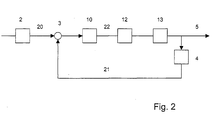
- the coarsened block diagram of Figure 2 illustrates the Functionality.
- the setpoint 20 coming from the setpoint sensor 2 is in the Control unit 3 compared with the actual value 21, which is supplied by the actual value sensor 4 is and the position of the steering column lever 5 reflects.
- the electric motor 10 which outputs a torque 22 to the control valve 12, which the Steering actuator 13 controls.
- FIG. 3 a structural unit is shown in more detail, which the electric motor 10, the reduction gear 11, a steering gear, the control valve 12 with the control sleeve 12a and a torsion bar 13 belonging to the control valve (Torsion bar).
- a second electric motor (not visible) is provided. Both electric motors replace each other as much as possible in the event of a fault. If the pinion 11a of the electric motor 10 rotates, the spur gear 11b of the Reduction gear 11 and the rotary valve 12b of the control valve turned. This rotary valve 12b is rigid with the right end of the Torsion bar 13 connected. The rotary movement of the rotary valve 12b is transmitted via the torsion bar 30 to the left end thereof, the torsion bar twisted. With the left end of the torsion bar 30, a tube 31 is rigid connected, the extension on the right side the control sleeve 12a forms.
- the tube 31 is enclosed by a piston 32, of which on the left and on the right, a working space 33 and 34 extends, filled with hydraulic oil.
- a Rotary movement of the tube 31 about its longitudinal axis has a Ball nut transmission with balls 37 result in the piston 32 following moved left or right. Since the piston on its underside one Toothing 35 shows, a toothed segment shaft 36 is rotated, which in Figure 1 shown steering column lever 5 (not visible) carries.
- Hydraulic oil is either in the left work space via the control valve 12 33 or directed into the right work space 34, so that the piston 32 after right or left is pressed and the toothing 35 Rotational movement of the toothed segment shaft 36 is supported.
Landscapes
- Engineering & Computer Science (AREA)
- Chemical & Material Sciences (AREA)
- Combustion & Propulsion (AREA)
- Transportation (AREA)
- Mechanical Engineering (AREA)
- Power Steering Mechanism (AREA)
- Steering Control In Accordance With Driving Conditions (AREA)
Abstract
Description
Der Elektromotor und das Untersetzungsgetriebe sind nämlich derart dimensioniert, dass sie bei Ausfall der hydraulischen Lenkfunktion die gesetzlich vorgeschriebene Mindestlenkleistung erbringen können.
Schematisch ist gezeigt in
- Figur 1:
- eine Übersichtsskizze einer erfindungsgemäßen Fremdkraft-Lenkeinrichtung,
- Figur 2:
- ein Prinzip-Blockschaltbild eines Regelkreises für eine erfindungsgemäße Fremdkraft-Lenkeinrichtung,
- Figur 3:
- eine Detaildarstellung eines Lenkstellers, wie in Figur 1 enthalten.
Claims (4)
- Fremdkraft-Lenkeinrichtung nach dem Steer-By-Wire-Prinzip, mit einem hydraulischen Steuerventil (12) zur Steuerung eines hydraulischen Lenkstellers (13) und mit einem Elektromotor (10) zur Aufbringung des Drehmomentes, durch welches das Steuerventil (10) gesteuert wird, sowie mit einem Sollwertsensor (2) für eine Lenkhandhabe (1), welcher Sollwerte für einen Regelkreis liefert, in welchem der Lenksteller (13) in der Regelstrecke angeordnet ist, an welcher ein Istwertsensor (4) vorgesehen ist,
wobei in dem vom Elektromotor (10) ausgehenden Drehmomentübertragungsstrang zwischen Elektromotor (10) und Steuerventil (12) ein Untersetzungsgetriebe (11) angeordnet ist und der Drehmomentübertragungsstrang ständig von der Lenkhandhabe (1) mechanisch entkoppelt ist,
gekennzeichnet durch folgende Merkmale:das Steuerventil (12) ist in dem Drehmomentübertragungsstrang zwischen dem Untersetzungsgetriebe (11) und dem hydraulischen Lenksteller (13) angeordnet,die über den Drehmomentübertragungsstrang ausübbare elektro-mechanische Lenkfunktion und die über das Steuerventil (12) und den Lenksteller (13) ausübbare hydraulische Lenkfunktion unterstützen einander im Normalbetrieb und sind so gesteuert, dass die elektro-mechanische Lenkfunktion im Notbetrieb als Rückfallebene für die hydraulische Lenkfunktion wirkt,der Elektromotor (10) und das Untersetzungsgetriebe (11) sind dem entsprechend so dimensioniert, dass sie bei Ausfall der hydraulischen Lenkfunktion in der Lage sind, eine vorgeschriebene Mindestlenkleistung zu erbringen. - Fremdkraft-Lenkeinrichtung nach Anspruch 1, dadurch gekennzeichnet, dass das Steuerventil (12) ein Drehschieberventil ist.
- Fremdkraft-Lenkeinrichtung nach Anspruch 1 oder 2, dadurch gekennzeichnet, dass zusätzlich zum Elektromotor (10) ein zweiter Elektromotor vorgesehen ist.
- Fremdkraft-Lenkeinrichtung nach einem der Ansprüche 1 bis 3, dadurch gekennzeichnet, dass der Lenksteller (13) zur Einwirkung auf die Vorderräder (7) eines Fahrzeugs vorgesehen ist.
Applications Claiming Priority (2)
| Application Number | Priority Date | Filing Date | Title |
|---|---|---|---|
| DE10060832 | 2000-12-07 | ||
| DE10060832A DE10060832A1 (de) | 2000-12-07 | 2000-12-07 | Fremdkraft-Lenkeinrichtung |
Publications (3)
| Publication Number | Publication Date |
|---|---|
| EP1213205A2 true EP1213205A2 (de) | 2002-06-12 |
| EP1213205A3 EP1213205A3 (de) | 2003-07-09 |
| EP1213205B1 EP1213205B1 (de) | 2004-09-29 |
Family
ID=7666150
Family Applications (1)
| Application Number | Title | Priority Date | Filing Date |
|---|---|---|---|
| EP20010117091 Expired - Lifetime EP1213205B1 (de) | 2000-12-07 | 2001-07-13 | Fremdkraft-Lenkeinrichtung |
Country Status (2)
| Country | Link |
|---|---|
| EP (1) | EP1213205B1 (de) |
| DE (2) | DE10060832A1 (de) |
Cited By (8)
| Publication number | Priority date | Publication date | Assignee | Title |
|---|---|---|---|---|
| FR2865988A1 (fr) * | 2004-02-11 | 2005-08-12 | Koyo Steering Europe Kse | Direction a assistance variable hydraulique de vehicule automobile |
| EP1582437A1 (de) * | 2004-04-01 | 2005-10-05 | TRW Automotive U.S. LLC | Fahrgeschwindigkeitsabhängige Steuerung einer Servolenkung |
| US6966398B2 (en) | 2003-03-26 | 2005-11-22 | Trw Automotive U.S. Llc | Apparatus for controlling a power-assisted steering gear in response to vehicle speed |
| CN102947165A (zh) * | 2010-06-23 | 2013-02-27 | 蒂森克虏伯普利斯坦有限公司 | 旋转支撑的转向轴 |
| US9145169B2 (en) * | 2013-12-24 | 2015-09-29 | Korea Advanced Institute Of Science And Technology | Steering apparatus of in-wheel motor-driven |
| WO2018050568A1 (fr) | 2016-09-19 | 2018-03-22 | Mmt ag | Systeme de direction electrohydraulique assistee pilotee electroniquement pour vehicules utilitaires, pompe et boitier de direction pour un tel systeme |
| EP4417488A1 (de) * | 2023-02-15 | 2024-08-21 | KNORR-BREMSE Systeme für Nutzfahrzeuge GmbH | Lenksystem für ein nutzfahrzeug, nutzfahrzeug mit einem lenksystem und verfahren zum betreiben eines lenksystems |
| WO2024213371A1 (de) * | 2023-04-14 | 2024-10-17 | Knorr-Bremse Systeme für Nutzfahrzeuge GmbH | Lenkbetätigungsvorrichtung |
Families Citing this family (9)
| Publication number | Priority date | Publication date | Assignee | Title |
|---|---|---|---|---|
| DE10227236A1 (de) * | 2002-06-19 | 2004-01-22 | Zf Lenksysteme Gmbh | Hydrolenkung für Kraftfahrzeuge |
| DE10244069A1 (de) * | 2002-09-06 | 2004-03-11 | Volkswagen Ag | Vorrichtung und Verfahren zur Verbesserung des Rücklaufverhaltens für Fahrzeuge mit elektromechanischer Lenkung |
| DE10331597A1 (de) | 2003-07-11 | 2005-02-03 | Zf Lenksysteme Gmbh | Aktuator, insbesondere Radaktuator mit einem Abtrieb |
| DE10331598A1 (de) * | 2003-07-11 | 2005-02-10 | Zf Lenksysteme Gmbh | Aktuator |
| DE102008021973A1 (de) | 2008-05-02 | 2009-11-05 | Bayerische Motoren Werke Aktiengesellschaft | Fahrzeug- Lenksystem der by-wire-Bauart |
| DE102009018047A1 (de) | 2009-04-18 | 2010-10-21 | Bayerische Motoren Werke Aktiengesellschaft | Fahrzeug-Lenksystem der by-wire-Bauart |
| DE102010009362A1 (de) | 2010-02-25 | 2011-08-25 | Thyssenkrupp Presta Ag | Lenksystem mit hydraulischer Lenksäule |
| CN103287491B (zh) * | 2013-04-27 | 2015-12-09 | 燕山大学 | 巷道无轨轮式液压动力车组柔性转向控制系统 |
| DE102015222864C5 (de) | 2015-11-19 | 2024-03-07 | Volkswagen Aktiengesellschaft | Servosystem und hydraulisches Lenksystem für ein Fahrzeug |
Citations (3)
| Publication number | Priority date | Publication date | Assignee | Title |
|---|---|---|---|---|
| DE4141406A1 (de) | 1991-12-16 | 1993-06-17 | Bosch Gmbh Robert | Elektrohydraulische stelleinrichtung zum betaetigen der hinterrad-lenkung eines kraftfahrzeuges |
| DE19541752A1 (de) | 1995-11-09 | 1997-05-15 | Daimler Benz Ag | Servolenkung für Kraftfahrzeuge |
| DE19840625A1 (de) | 1998-09-05 | 2000-03-09 | Daimler Chrysler Ag | Lenkventilanordnung eines hydraulischen Lenksystems |
Family Cites Families (6)
| Publication number | Priority date | Publication date | Assignee | Title |
|---|---|---|---|---|
| GB1424937A (en) * | 1973-03-05 | 1976-02-11 | Nissan Motor | Automotive steering system process for the production of bis-halogen carbonyl anilines |
| EP0309460B1 (de) * | 1986-05-14 | 1990-02-07 | ZF FRIEDRICHSHAFEN Aktiengesellschaft | Hilfskraftlenkung für kraftfahrzeuge |
| DE3918987A1 (de) * | 1988-06-15 | 1989-12-21 | Zahnradfabrik Friedrichshafen | Hilfskraftlenkung fuer kraftfahrzeuge |
| DE19541749C1 (de) * | 1995-11-09 | 1997-05-22 | Daimler Benz Ag | Servolenkung für Kraftfahrzeuge |
| DE19754258A1 (de) * | 1997-12-06 | 1999-06-10 | Bosch Gmbh Robert | Verfahren zur Betätigung eines Steer-by-Wire-Lenkantriebs |
| DE19838490A1 (de) * | 1998-06-25 | 1999-12-30 | Bosch Gmbh Robert | Lenksystem mit hydraulischer Rückfallebene |
-
2000
- 2000-12-07 DE DE10060832A patent/DE10060832A1/de not_active Withdrawn
-
2001
- 2001-07-13 DE DE50103858T patent/DE50103858D1/de not_active Expired - Lifetime
- 2001-07-13 EP EP20010117091 patent/EP1213205B1/de not_active Expired - Lifetime
Patent Citations (3)
| Publication number | Priority date | Publication date | Assignee | Title |
|---|---|---|---|---|
| DE4141406A1 (de) | 1991-12-16 | 1993-06-17 | Bosch Gmbh Robert | Elektrohydraulische stelleinrichtung zum betaetigen der hinterrad-lenkung eines kraftfahrzeuges |
| DE19541752A1 (de) | 1995-11-09 | 1997-05-15 | Daimler Benz Ag | Servolenkung für Kraftfahrzeuge |
| DE19840625A1 (de) | 1998-09-05 | 2000-03-09 | Daimler Chrysler Ag | Lenkventilanordnung eines hydraulischen Lenksystems |
Cited By (11)
| Publication number | Priority date | Publication date | Assignee | Title |
|---|---|---|---|---|
| US6966398B2 (en) | 2003-03-26 | 2005-11-22 | Trw Automotive U.S. Llc | Apparatus for controlling a power-assisted steering gear in response to vehicle speed |
| US7055643B2 (en) | 2003-03-26 | 2006-06-06 | Trw Automotive U.S. Llc | Apparatus for controlling a power-assisted steering gear in response to vehicle speed |
| FR2865988A1 (fr) * | 2004-02-11 | 2005-08-12 | Koyo Steering Europe Kse | Direction a assistance variable hydraulique de vehicule automobile |
| EP1582437A1 (de) * | 2004-04-01 | 2005-10-05 | TRW Automotive U.S. LLC | Fahrgeschwindigkeitsabhängige Steuerung einer Servolenkung |
| CN102947165A (zh) * | 2010-06-23 | 2013-02-27 | 蒂森克虏伯普利斯坦有限公司 | 旋转支撑的转向轴 |
| US9145169B2 (en) * | 2013-12-24 | 2015-09-29 | Korea Advanced Institute Of Science And Technology | Steering apparatus of in-wheel motor-driven |
| WO2018050568A1 (fr) | 2016-09-19 | 2018-03-22 | Mmt ag | Systeme de direction electrohydraulique assistee pilotee electroniquement pour vehicules utilitaires, pompe et boitier de direction pour un tel systeme |
| FR3056181A1 (fr) * | 2016-09-19 | 2018-03-23 | Mmt ag | Systeme de direction electrohydraulique assistee pilotee electroniquement pour vehicules utilitaires, pompe et boitier de direction pour un tel systeme. |
| EP4417488A1 (de) * | 2023-02-15 | 2024-08-21 | KNORR-BREMSE Systeme für Nutzfahrzeuge GmbH | Lenksystem für ein nutzfahrzeug, nutzfahrzeug mit einem lenksystem und verfahren zum betreiben eines lenksystems |
| WO2024170277A1 (en) * | 2023-02-15 | 2024-08-22 | Knorr-Bremse Systeme für Nutzfahrzeuge GmbH | Steering system for a commercial vehicle, commercial vehicle with a steeringsystem and method for operating a steering system |
| WO2024213371A1 (de) * | 2023-04-14 | 2024-10-17 | Knorr-Bremse Systeme für Nutzfahrzeuge GmbH | Lenkbetätigungsvorrichtung |
Also Published As
| Publication number | Publication date |
|---|---|
| DE10060832A1 (de) | 2002-06-13 |
| EP1213205A3 (de) | 2003-07-09 |
| EP1213205B1 (de) | 2004-09-29 |
| DE50103858D1 (de) | 2004-11-04 |
Similar Documents
| Publication | Publication Date | Title |
|---|---|---|
| EP1213205B1 (de) | Fremdkraft-Lenkeinrichtung | |
| DE60307161T2 (de) | Aktives Vorderrad-Lenkungs-Stellglied und Verfahren zum Steuern eines Fahrzeugs | |
| DE112004001258B4 (de) | Vorrichtung zum Verschwenken lenkbarer Räder eines Fahrzeugs | |
| WO1997017247A1 (de) | Servolenkung für kraftfahrzeuge | |
| EP2271538A1 (de) | Fahrzeug-lenksystem der by-wire-bauart | |
| EP3762267B1 (de) | Lenkverfahren für ein autonom gelenktes fahrzeug | |
| DE10159330A1 (de) | Reaktionsmomentsimulator für ein Lenkrad einer Fahrzeuglenkung | |
| DE19713245C2 (de) | Kraftfahrzeug mit zumindest einem über wenigstens einen Bedienhebel in Form eines sogenannten Side-stick steuerbaren Teil | |
| DE10351618B4 (de) | Nutzfahrzeuglenkung | |
| DE102006008436A1 (de) | Mehrachslenkungsanlage | |
| DE19935073A1 (de) | Steer-by-wire-Lenkung mit hydraulischem Druckspeicher | |
| EP2421741B1 (de) | Fahrzeug-lenksystem der by-wire-bauart | |
| EP1399349A1 (de) | Lenkeinrichtung | |
| DE102006006141B4 (de) | Fahrzeuganhänger mit lenkbarer Achse | |
| DE102007012392A1 (de) | Hilfskraftlenkung | |
| EP1508498B1 (de) | Lenksystem für ein Kraftfahrzeug mit einer Servolenkeinrichtung | |
| DE10256306A1 (de) | Hydraulische Servolenkung | |
| DE102004002248A1 (de) | Lenksystem für ein Kraftfahrzeug mit einer Servolenkeinrichtung | |
| DE10253468A1 (de) | Servolenkung mit Rangier-Betriebsweise | |
| AT621U1 (de) | Antriebssteuerung eines einachstraktors | |
| DE102004038936C5 (de) | Hydraulische Servolenkung und Verfahren zum Betrieb einer hydraulischen Servolenkung | |
| DE19950926A1 (de) | Servolenkung für ein Kraftfahrzeug mit Ventilbetätigung über eine biegsame Welle | |
| EP1508499B1 (de) | Lenksystem für ein Kraftfahrzeug mit einer Servolenkeinrichtung | |
| DE10320846A1 (de) | Lenkungsvorrichtung für Kraftfahrzeuge | |
| DE10048697A1 (de) | Steer-by-Wire-Lenkanlage mit Zahnstangen-Hydrolenksteller |
Legal Events
| Date | Code | Title | Description |
|---|---|---|---|
| PUAI | Public reference made under article 153(3) epc to a published international application that has entered the european phase |
Free format text: ORIGINAL CODE: 0009012 |
|
| AK | Designated contracting states |
Kind code of ref document: A2 Designated state(s): AT BE CH CY DE DK ES FI FR GB GR IE IT LI LU MC NL PT SE TR |
|
| AX | Request for extension of the european patent |
Free format text: AL;LT;LV;MK;RO;SI |
|
| PUAL | Search report despatched |
Free format text: ORIGINAL CODE: 0009013 |
|
| AK | Designated contracting states |
Designated state(s): AT BE CH CY DE DK ES FI FR GB GR IE IT LI LU MC NL PT SE TR |
|
| AX | Request for extension of the european patent |
Extension state: AL LT LV MK RO SI |
|
| RIC1 | Information provided on ipc code assigned before grant |
Ipc: 7B 62D 5/30 A Ipc: 7B 62D 6/00 B |
|
| 17P | Request for examination filed |
Effective date: 20030725 |
|
| GRAP | Despatch of communication of intention to grant a patent |
Free format text: ORIGINAL CODE: EPIDOSNIGR1 |
|
| AKX | Designation fees paid |
Designated state(s): DE FR IT SE |
|
| GRAS | Grant fee paid |
Free format text: ORIGINAL CODE: EPIDOSNIGR3 |
|
| GRAA | (expected) grant |
Free format text: ORIGINAL CODE: 0009210 |
|
| AK | Designated contracting states |
Kind code of ref document: B1 Designated state(s): DE FR IT SE |
|
| REG | Reference to a national code |
Ref country code: IE Ref legal event code: FG4D Free format text: GERMAN |
|
| REF | Corresponds to: |
Ref document number: 50103858 Country of ref document: DE Date of ref document: 20041104 Kind code of ref document: P |
|
| REG | Reference to a national code |
Ref country code: SE Ref legal event code: TRGR |
|
| REG | Reference to a national code |
Ref country code: IE Ref legal event code: FD4D |
|
| ET | Fr: translation filed | ||
| PLBE | No opposition filed within time limit |
Free format text: ORIGINAL CODE: 0009261 |
|
| STAA | Information on the status of an ep patent application or granted ep patent |
Free format text: STATUS: NO OPPOSITION FILED WITHIN TIME LIMIT |
|
| 26N | No opposition filed |
Effective date: 20050630 |
|
| PGFP | Annual fee paid to national office [announced via postgrant information from national office to epo] |
Ref country code: SE Payment date: 20120711 Year of fee payment: 12 |
|
| PGFP | Annual fee paid to national office [announced via postgrant information from national office to epo] |
Ref country code: IT Payment date: 20120713 Year of fee payment: 12 Ref country code: FR Payment date: 20120719 Year of fee payment: 12 |
|
| REG | Reference to a national code |
Ref country code: SE Ref legal event code: EUG |
|
| REG | Reference to a national code |
Ref country code: FR Ref legal event code: ST Effective date: 20140331 |
|
| PG25 | Lapsed in a contracting state [announced via postgrant information from national office to epo] |
Ref country code: SE Free format text: LAPSE BECAUSE OF NON-PAYMENT OF DUE FEES Effective date: 20130714 |
|
| PG25 | Lapsed in a contracting state [announced via postgrant information from national office to epo] |
Ref country code: FR Free format text: LAPSE BECAUSE OF NON-PAYMENT OF DUE FEES Effective date: 20130731 Ref country code: IT Free format text: LAPSE BECAUSE OF NON-PAYMENT OF DUE FEES Effective date: 20130713 |
|
| REG | Reference to a national code |
Ref country code: DE Ref legal event code: R081 Ref document number: 50103858 Country of ref document: DE Owner name: ROBERT BOSCH AUTOMOTIVE STEERING GMBH, DE Free format text: FORMER OWNER: ZF LENKSYSTEME GMBH, 73527 SCHWAEBISCH GMUEND, DE Effective date: 20150423 |
|
| PGFP | Annual fee paid to national office [announced via postgrant information from national office to epo] |
Ref country code: DE Payment date: 20170927 Year of fee payment: 17 |
|
| REG | Reference to a national code |
Ref country code: DE Ref legal event code: R119 Ref document number: 50103858 Country of ref document: DE |
|
| PG25 | Lapsed in a contracting state [announced via postgrant information from national office to epo] |
Ref country code: DE Free format text: LAPSE BECAUSE OF NON-PAYMENT OF DUE FEES Effective date: 20190201 |