EP1213218A2 - Dispositif de suspension pour véhicule à deux roues - Google Patents
Dispositif de suspension pour véhicule à deux roues Download PDFInfo
- Publication number
- EP1213218A2 EP1213218A2 EP01128917A EP01128917A EP1213218A2 EP 1213218 A2 EP1213218 A2 EP 1213218A2 EP 01128917 A EP01128917 A EP 01128917A EP 01128917 A EP01128917 A EP 01128917A EP 1213218 A2 EP1213218 A2 EP 1213218A2
- Authority
- EP
- European Patent Office
- Prior art keywords
- hydraulic
- cylinders
- oil
- pressure regulating
- chamber
- Prior art date
- Legal status (The legal status is an assumption and is not a legal conclusion. Google has not performed a legal analysis and makes no representation as to the accuracy of the status listed.)
- Granted
Links
Images


Classifications
-
- B—PERFORMING OPERATIONS; TRANSPORTING
- B62—LAND VEHICLES FOR TRAVELLING OTHERWISE THAN ON RAILS
- B62K—CYCLES; CYCLE FRAMES; CYCLE STEERING DEVICES; RIDER-OPERATED TERMINAL CONTROLS SPECIALLY ADAPTED FOR CYCLES; CYCLE AXLE SUSPENSIONS; CYCLE SIDECARS, FORECARS, OR THE LIKE
- B62K25/00—Axle suspensions
- B62K25/04—Axle suspensions for mounting axles resiliently on cycle frame or fork
-
- B—PERFORMING OPERATIONS; TRANSPORTING
- B62—LAND VEHICLES FOR TRAVELLING OTHERWISE THAN ON RAILS
- B62K—CYCLES; CYCLE FRAMES; CYCLE STEERING DEVICES; RIDER-OPERATED TERMINAL CONTROLS SPECIALLY ADAPTED FOR CYCLES; CYCLE AXLE SUSPENSIONS; CYCLE SIDECARS, FORECARS, OR THE LIKE
- B62K25/00—Axle suspensions
- B62K25/04—Axle suspensions for mounting axles resiliently on cycle frame or fork
- B62K2025/044—Suspensions with automatic adjustment
Definitions
- This invention relates to a suspension device for a two-wheeled vehicle, in particular a motorcycle, comprising first and second hydraulic cylinders respectively suspending front and rear wheels having pistons connected to one end of a piston rod inserted in the hydraulic cylinder and a pressure regulating device.
- Fig. 4 is a diagrammatic sectional illustration of the construction of a conventional suspension for a vehicle, and this suspension for a vehicle comprises an oil cylinder 1' for suspending the front wheel, an oil cylinder 11' for suspending the rear wheel, and a pressure regulating device 20'.
- the oil cylinders 1', 11' are arranged such that pistons 4', 14' connected to the lower ends of piston rods 3', 13' inserted from below into cylinders 2', 12', are disposed in the cylinders 2', 12' for sliding movement; upper oil chambers 6', 16' and lower oil chambers 7', 17' defined by pistons 4', 14' in the cylinders 2', 12' are filled with oil; and in oil holes 4a', 14a' are provided chokes 5', 15'.
- the pressure regulating device 20' is arranged such that a first pressure regulating cylinder 21' having a first oil chamber 23' in communication with the upper oil chamber 6' of the oil cylinder 1' for the front wheel through an oil path 24' and a second pressure regulating cylinder 31' having a second oil chamber 33' in communication with the upper oil chamber 16' of the oil cylinder 11' for the rear wheel through an oil path 34', are formed integrally; and the two oil chambers 23', 33' and a gas chamber 28' are defined by one free piston 22' as a movable partition. Between the first oil chamber 23' and the second oil chamber 33' is provided a choke 27'. The free piston 22' is formed such that effective sectional areas of the first oil chamber 23' and the second oil chamber 33' are equal to each other.
- a suspension device for a two-wheeled vehicle comprising first and second hydraulic cylinders respectively suspending front and rear wheels having pistons connected to one end of piston rods inserted in the hydraulic cylinders, and a pressure regulating device with first and second pressure regulating cylinders having hydraulic chambers respectively in communication with one of said hydraulic cylinders, a communication passage for providing communication between said hydraulic chambers and at least one movable partition, wherein the first and the second pressure regulating cylinders each comprise a slidable free piston as a movable partition, wherein a first hydraulic chamber is constituted by the first pressure regulating cylinder and the respective movable partition and a second hydraulic chamber is constituted by the second pressure regulating cylinder and the respective movable partition.
- the communication passage comprises a first and a second choke, wherein the first choke provides hydraulic liquid flow from the first to the second hydraulic chamber and the second choke from the second to the first hydraulic chamber.
- a ratio of an amount of displacement of the front and rear wheels to piston strokes of the respective hydraulic cylinders are set at different values.
- a mutual gas chamber is formed in the first and the second pressure regulating cylinders, wherein the mutual gas chamber contains an inert gas.
- At least either one of relations a1 ⁇ a2 and S1/ ⁇ 1 ⁇ S2/ ⁇ 2 is satisfied and the relation (S1/ ⁇ 1) x (a1/A1) ⁇ (S2/ ⁇ 2) x (a2/A2) applies, wherein S1 and S2 are piston strokes of said first and second hydraulic cylinders, a1 and a2 are sectional areas of the piston rods, ⁇ 1 and ⁇ 2 are amounts of vertical displacement of the front and rear wheels at grounding points for the piston strokes S1 and S2 of the first and second hydraulic cylinders, and A1 and A2 are effective sectional areas of said first and second pressure regulating cylinders.
- absolute values of a displacement velocity of the front and rear wheels are set equal, and the relation (S1/ ⁇ 1) x (a1/A1) x ⁇ ⁇ ⁇ (S2/ ⁇ 2) x (a2/A2) x ⁇ ⁇ ' applies, wherein ⁇ ⁇ is a pressure difference between the hydraulic chambers when a hydraulic liquid flows from the first hydraulic chamber to the second hydraulic chamber, ⁇ ⁇ ' is a pressure difference between the hydraulic chambers when a hydraulic liquid flows from the second hydraulic chamber to the first hydraulic chamber.
- At least one value of pairs of values of a1 and a2, S1/ ⁇ 1 and S2/ ⁇ 2, and a damping force characteristic of hydraulic liquid flowing from the first to the second hydraulic chamber through one choke and a damping force characteristic of hydraulic liquid flowing from the second to the first hydraulic chamber through the other choke is set to be different from the other, wherein S1 and S2 are the piston strokes of said first and second hydraulic cylinders, a1 and a2 are sectional areas of the piston rods of said first and second hydraulic cylinders, ⁇ 1 and ⁇ 2 are amounts of vertical displacement of the front and rear wheels at grounding points for the piston strokes S1 and S2 of the first and second hydraulic cylinders.
- a suspension device in which the magnitude of the additional damping force can be balanced to the diving an squatting motion of the vehicle body.
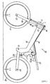
- Fig. 1 is a schematic side view of a motorcycle with a suspension
- Fig. 2 is a diagrammatic illustration of the construction of the suspension.
- numeral 53 designates a head pipe located at the upper front of the vehicle body, and in the head pipe 53 is inserted a steering shaft (not shown) for rotation.
- a front fork 56 To the steering shaft is mounted a front fork 56 through an upper bracket 54 and a lower bracket 55, and at the lower ends of the front fork 56 is supported a front wheel 51 on an axle 57 for rotation.
- an oil cylinder (hydraulic chamber) 1 In front of the front fork 56 is disposed an oil cylinder (hydraulic chamber) 1, and the upper end of the oil cylinder (hydraulic cylinder) 1 is attached to the upper bracket 54 on the body side, and its lower end to a bracket 58 on the front wheel side.
- a main frame 59 extends from the head pipe 53 obliquely downwardly toward the rear of the vehicle body, and to the rear end of the main frame 59 is mounted the forward end of a rear arm 60 on a pivot shaft 61 for rotation. At the rear ends of the rear arm 60 is supported a rear wheel 52 on an axle 62 for rotation.
- a pair of left and right seat rail frames 63 extend obliquely upwardly toward the rear, and between the seat rail frames 63 and the rear arm 60 is disposed an oil cylinder (hydraulic cylinder) 11.
- a pressure regulating device 20 In addition, to the seat rail frames 63 is attached a pressure regulating device 20, and to the pressure regulating device 20 are connected the oil cylinders (hydraulic cylinders) 1, 11 through oil paths 24, 34.
- the suspension for a motorcycle includes the oil cylinders (hydraulic cylinders) 1, 11 and the pressure-regulating device 20, the construction of which will be described in detail with reference to Fig. 2.
- the oil cylinders 1, 11 on the front wheel 51 and the rear wheel 52 side are arranged such that pistons 4, 14 connected to the upper ends of piston rods 3, 13 inserted into cylinders 2, 12 from above, are inserted in the cylinders 2, 13 for sliding movement; upper oil chambers 6, 16 and lower oil chambers 7, 17 defined by the pistons 4, 14 in the cylinders 2, 12 are filled with oil; and chokes 5, 15 are disposed in oil holes 4a, 14a formed in the pistons 4, 14.
- the oil cylinder 11 on the rear wheel 52 side is constituted by a shock absorber, this may be a special cylinder, like the oil cylinder 1 on the front wheel 51 side.
- an oil cylinder smaller (in diameter) than the oil cylinder 11 on the rear wheel 52 side an oil cylinder smaller (in diameter) than the oil cylinder 11 on the rear wheel 52 side, and sectional areas a1, a2 of the piston rods 3, 13 in the oil cylinders 1, 11 are set at different values.
- the ratio (hereinafter referred to as the lever ratio) of the amounts of displacement of the first and rear wheels 51, 52 to the piston strokes of the oil cylinders 1, 11 are also set at different values. Specifically, supposing the amounts of vertical displacement at grounding points of the front and rear wheels 51, 52 be ⁇ 1, ⁇ 2 for the piston strokes S1, S2 of the oil cylinders 1, 11, as shown in Fig. 1, the lever ratio (S1/ ⁇ 1) on the front wheel 51 side and the lever ratio (S2/ ⁇ 2) on the rear wheel 52 side are set at different values.
- the pressure regulating device 20 is arranged such that movable partitions or free pistons 22, 23 are fitted, for sliding movement, in first and second pressure regulating cylinders 21, 31 connected together; a first oil chamber 23 defined by the free piston 22 in the first pressure regulating cylinder 21 is in communication with the upper oil chamber 6 of the oil cylinder 1 on the front wheel 51 side through the oil path 24; and a second oil chamber 33 defined by the free piston 32 in the second pressure regulating cylinder 31 is in communication with the upper oil chamber 16 of the oil cylinder 11 on the rear wheel 52 side through the oil path 34.
- Effective sectional areas A1, A2 of the first and second pressure regulating cylinders 21, 31 are set at different values.
- the free pistons 22, 32 are connected by a connecting member 25 such that volume changes of the first and second oil chambers 23, 33 are in agreement with each other.
- the first oil chamber 23 and the second oil chamber 33 are in communication with each other through a communication passage 26, and in the communication passage 26 are provided a first choke 27 and a second choke 37.
- the first choke 27 allows an oil flow from the first oil chamber 23 to the second oil chamber 33, and the second choke 37 conversely from the second oil chamber 33 to the first oil chamber 23.
- first and second pressure regulating cylinders 21, 31 is formed a common gas chamber 28 defined by the free pistons 22, 32; the first and second oil chambers 23, 33 are filled with oil; and the gas chamber 28 contains inert gas.
- the pressure in the first oil chamber is represented by P1 and the pressure in the second chamber by P2.
- the cylinders 2, 12 of the oil cylinders 1, 11 and the piston rods 3, 13 extend and contract, causing the pistons 4, 14 to slide in the cylinders 2, 12, so that the shock the front and rear wheels 51, 52 receives from the road surface is absorbed by the damping force generated when oil passes through the chokes 5, 15 provided in the oil holes 4a, 14a in the pistons 4, 14.
- amounts of oil in the cylinders 2, 12 of the oil cylinders 1,11 increase/decrease by as much quantity as volume changes of the cylinders 2, 12 in association with the extending and retracting movement of the piston rods 3, 13, respectively; the increased/decreased amounts of oil travel through oil paths 24, 34 between the upper oil chambers 6, 16 in the oil cylinders 1, 11 and the first and second oil chambers 23, 33 of the pressure regulating cylinders 21, 31, respectively, causing the free piston 22, 32 to slide in the pressure regulating cylinders 21, 31 in one body; and the changes in the amount of oil are relieved by gas being compressed and expanded in the gas chamber 28.
- ) of Q1 and Q2 flows from the first oil chamber 23 to the second oil chamber 33 through the first choke 27, or conversely, from the second oil chamber 33 to the first oil chamber 23 through the second choke 37, so that an unnecessary additional damping force is generated when the oil passes through the choke 27 or 37.
- this inventor has found that supposing piston strokes of the oil cylinders 1, 11 be S1 and S2, sectional areas of the piston rods 3, 13 be a1 and a2, and amounts of vertical displacement of the front and rear wheels 51, 52 at the grounding points be ⁇ 1 and ⁇ 2, if between these variables, at least either one of expressions a1 ⁇ a2 and S1/ ⁇ 1 ⁇ S2/ ⁇ 2 is satisfied, and the following relation holds: (S1/ ⁇ 1)x(a1/A1) ⁇ (S2/ ⁇ 2) x (a2/A2) generation of an unnecessary additional damping force to the bouncing motion can be prevented.
- oil equivalent to volume changes of the cylinders 2, 12 in association with the extending and retracting movement of the piston rods 3, 13 flows through the choke 27 or 37 of the pressure regulating device 20 to thereby generate an additional damping force, and this additional damping force is added to damping forces generated in the oil cylinders 1, 11, so that operations of the oil cylinders 1, 11 in the different directions are restricted, preventing diving or squatting of the vehicle body.
- the oil cylinder 1 on the front wheel 51 side is compressed and the oil cylinder 11 on the rear wheel 52 side is extended, so that oil is discharged from the oil cylinder 1 on the front wheel 51 side and flows into the oil cylinder 11 on the rear wheel 52 side.
- the oil discharged from the oil cylinder 1 on the front wheel 51 side flows through the oil path 24 into the first oil chamber 23 of the pressure regulating device 20, and part of the oil flows through the first choke 27 to the second oil chamber 33, so that an additional damping force is generated when the part of the oil passes through the first choke 27.
- the oil cylinder 1 on the front wheel 51 side is extended and the oil cylinder 11 on the rear wheel 52 side is compressed, so that oil flows into the oil cylinder 1 on the front wheel 51 side and is discharged from the oil cylinder 11 on the front wheel 52 side.
- the oil discharged from the oil cylinder 11 on the rear wheel 52 side flows through the oil path 34 into the second oil chamber 33 of the pressure regulating device 20, and part of the oil flows through the second choke 37 to the first oil chamber 23, so that an additional damping force is generated when the part of the oil passes through the second choke 37.
- ⁇ ⁇ in the relation (2) represents the pressure difference (P1-P2) between two oil chambers 23, 33 when oil flows from the first oil chamber 23 to the second oil chamber 33, and ⁇ ' the pressure difference (P1-P2) between two oil chambers 23, 33 when oil flows from the second oil chamber 33 to the first oil chamber 23.
- the relation (2) is derived such that a first condition under which the additional damping force generated in the first choke 27 during rapid deceleration is equal to that generated in the second choke 37 during rapid acceleration and a second condition under which the additional damping force generated in the second choke 37 during rapid deceleration is equal to that generated in the first choke 27 during rapid acceleration, are determined, and both of these two conditions are satisfied. Description of the procedure for the relation (2) is omitted (refer to Japanese Patent Application Hei 2000-003385 for details).
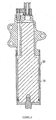
- FIG. 3 is a sectional view showing the construction of the leakage detection device.
- the opening is closed air-tightly by a lid member to pressurize/depressurize the interior of the container, and it is determined whether or not leakage happened, from a change in the internal pressure after a given elapsed time.
- a lid member 71 for closing the opening of the pressure container 70 is disposed in the pressure container 70 so that the volume of the pressure container 70 will be decreased by as much volume as the lid member 71. Therefore, the volume of the pressure container 70 can be kept far smaller than a conventional container, so that leakage inspection of the pressure container 70 can be performed in a short time with higher accuracy.
- a suspension for a motor cycle comprising first and second oil cylinders each having a piston connected to one end of a piston rod inserted in the cylinder, said first and second oil cylinders suspending front and rear wheels, respectively; a first pressure regulating cylinder having a first oil chamber in communication with said first oil cylinder and a movable partition fitted in said first oil chamber for sliding movement; a second pressure regulating cylinder having a second oil chamber in communication with said second oil cylinder and a movable partition fitted in said second oil chamber for sliding movement; said movable partitions being connected to each other such that volume changes of said first and second oil chambers in both pressure regulating cylinders being in agreement with each other; and chokes disposed in a communication passage for providing communication between said first and second oil chambers, wherein supposing piston strokes of said first and second oil cylinders be S1 and S2, sectional areas of the piston rods be a1 and a2, amounts of vertical displacement of the front and rear wheels at grounding points
- supposing pressures of the first and second oil chambers in said first and second pressure regulating cylinders be P1 and P2, a pressure difference between oil chambers when oil flows from the first oil chamber to the second oil chamber be ⁇ , and a pressure difference between oil chambers when oil flows from the second oil chamber to the first oil chamber be ⁇ ', and when, of pairs of values of a1 and a2, S1/ ⁇ 1 and S2/ ⁇ 2, and a damping force characteristic of oil flowing from the first oil chamber of the first pressure regulating cylinder to the second oil chamber of the second pressure regulating cylinder through one choke and a damping force characteristic of oil flowing from the second oil chamber of the second pressure regulating cylinder to the first oil chamber of the first pressure regulating cylinder through the other choke, one value of at least any one of said pairs of values is set to be different from the other, the front and rear wheels are displaced in the opposite directions, and absolute values of the displacement velocity are the same, the following relation holds: (S1/ ⁇ 1) x (a1/A
- a suspension for a motorcycle in which no unnecessary additional damping force to the bouncing movement of the vehicle body is generated, wherein supposing piston strokes of the first and second oil cylinders 1, 11 be S1 and S2, sectional areas of the piston rods 3, 13 be a1 and a2, amounts of vertical displacement of the front and rear wheels at grounding points be ⁇ 1 and ⁇ 2 for the piston strokes S1 and S2 of the first and second oil cylinders 1, 11, and effective sectional areas of the first and second pressure regulating cylinders 21, 31 be A1 and A2, at least either one of expressions a1 ⁇ a2 and S1/ ⁇ 1 ⁇ S2/ ⁇ 2 is satisfied, and the following relation holds: (S1/ ⁇ 1) x (a1/A1) ⁇ (S2/ ⁇ 2) x (a2/A2).
Landscapes
- Engineering & Computer Science (AREA)
- Mechanical Engineering (AREA)
- Axle Suspensions And Sidecars For Cycles (AREA)
- Vehicle Body Suspensions (AREA)
- Fluid-Damping Devices (AREA)
- Automatic Cycles, And Cycles In General (AREA)
Applications Claiming Priority (2)
| Application Number | Priority Date | Filing Date | Title |
|---|---|---|---|
| JP2000371656 | 2000-12-06 | ||
| JP2000371656A JP4426717B2 (ja) | 2000-12-06 | 2000-12-06 | 二輪車用サスペンション |
Publications (3)
| Publication Number | Publication Date |
|---|---|
| EP1213218A2 true EP1213218A2 (fr) | 2002-06-12 |
| EP1213218A3 EP1213218A3 (fr) | 2003-08-13 |
| EP1213218B1 EP1213218B1 (fr) | 2008-05-28 |
Family
ID=18841344
Family Applications (1)
| Application Number | Title | Priority Date | Filing Date |
|---|---|---|---|
| EP01128917A Expired - Lifetime EP1213218B1 (fr) | 2000-12-06 | 2001-12-05 | Dispositif de suspension pour véhicule à deux roues |
Country Status (4)
| Country | Link |
|---|---|
| EP (1) | EP1213218B1 (fr) |
| JP (1) | JP4426717B2 (fr) |
| AT (1) | ATE396910T1 (fr) |
| DE (1) | DE60134206D1 (fr) |
Cited By (3)
| Publication number | Priority date | Publication date | Assignee | Title |
|---|---|---|---|---|
| US7281722B2 (en) * | 2004-02-23 | 2007-10-16 | Yamaha Motor Co., Ltd. | Wheeled vehicle with suspension units |
| WO2013117777A1 (fr) * | 2012-02-09 | 2013-08-15 | Fundacion Tekniker | Système de suspension pour véhicule |
| EP3203105A4 (fr) * | 2014-09-29 | 2018-05-30 | KYB Corporation | Dispositif de suspension |
Families Citing this family (2)
| Publication number | Priority date | Publication date | Assignee | Title |
|---|---|---|---|---|
| JP4658619B2 (ja) * | 2005-01-11 | 2011-03-23 | ランドウォーカー株式会社 | 双輪自転車 |
| KR20170042911A (ko) * | 2015-10-12 | 2017-04-20 | 태평양정기(주) | 서스펜션 |
Citations (2)
| Publication number | Priority date | Publication date | Assignee | Title |
|---|---|---|---|---|
| JPH08132846A (ja) | 1994-08-05 | 1996-05-28 | Yamaha Motor Co Ltd | 4輪車用懸架装置 |
| JP2000003385A (ja) | 1996-05-06 | 2000-01-07 | Amada Metrecs Co Ltd | 薄板金属製作設備全体にわたって設計製作情報を分配する装置および方法 |
Family Cites Families (7)
| Publication number | Priority date | Publication date | Assignee | Title |
|---|---|---|---|---|
| JPS60154907A (ja) * | 1984-01-24 | 1985-08-14 | Yamaha Motor Co Ltd | 車両の姿勢制御装置 |
| JPS62120290A (ja) * | 1985-11-19 | 1987-06-01 | 株式会社 昭和製作所 | 自動二輪車のクツシヨン機構 |
| JP3391487B2 (ja) * | 1992-06-22 | 2003-03-31 | ヤマハ発動機株式会社 | 4輪車用懸架装置 |
| US5486018A (en) * | 1994-08-05 | 1996-01-23 | Yamaha Hatsudoki Kabushiki Kaisha | Suspension system for four-wheeled vehicles |
| DE9415009U1 (de) * | 1994-09-15 | 1996-01-18 | Yamaha Hatsudoki K.K., Iwata, Shizuoka | Radaufhängungssystem für zweispurige Fahrzeuge |
| JPH09193641A (ja) * | 1996-01-19 | 1997-07-29 | Yamaha Motor Co Ltd | 車両用懸架装置およびその減衰性能設定方法 |
| JP4319309B2 (ja) * | 1999-11-11 | 2009-08-26 | ヤマハ発動機株式会社 | 車両用懸架装置 |
-
2000
- 2000-12-06 JP JP2000371656A patent/JP4426717B2/ja not_active Expired - Fee Related
-
2001
- 2001-12-05 EP EP01128917A patent/EP1213218B1/fr not_active Expired - Lifetime
- 2001-12-05 DE DE60134206T patent/DE60134206D1/de not_active Expired - Fee Related
- 2001-12-05 AT AT01128917T patent/ATE396910T1/de not_active IP Right Cessation
Patent Citations (2)
| Publication number | Priority date | Publication date | Assignee | Title |
|---|---|---|---|---|
| JPH08132846A (ja) | 1994-08-05 | 1996-05-28 | Yamaha Motor Co Ltd | 4輪車用懸架装置 |
| JP2000003385A (ja) | 1996-05-06 | 2000-01-07 | Amada Metrecs Co Ltd | 薄板金属製作設備全体にわたって設計製作情報を分配する装置および方法 |
Cited By (4)
| Publication number | Priority date | Publication date | Assignee | Title |
|---|---|---|---|---|
| US7281722B2 (en) * | 2004-02-23 | 2007-10-16 | Yamaha Motor Co., Ltd. | Wheeled vehicle with suspension units |
| EP1566330A3 (fr) * | 2004-02-23 | 2008-08-20 | Yamaha Hatsudoki Kabushiki Kaisha | Suspension de véhicule à roues |
| WO2013117777A1 (fr) * | 2012-02-09 | 2013-08-15 | Fundacion Tekniker | Système de suspension pour véhicule |
| EP3203105A4 (fr) * | 2014-09-29 | 2018-05-30 | KYB Corporation | Dispositif de suspension |
Also Published As
| Publication number | Publication date |
|---|---|
| JP2002173074A (ja) | 2002-06-18 |
| DE60134206D1 (de) | 2008-07-10 |
| EP1213218B1 (fr) | 2008-05-28 |
| JP4426717B2 (ja) | 2010-03-03 |
| ATE396910T1 (de) | 2008-06-15 |
| EP1213218A3 (fr) | 2003-08-13 |
Similar Documents
| Publication | Publication Date | Title |
|---|---|---|
| JP4674882B2 (ja) | 車両懸架システム用の受動的ライド制御 | |
| EP1362196B1 (fr) | Systeme de controle pour suspension de vehicule | |
| US8960697B2 (en) | Suspension device for vehicle | |
| JP4193737B2 (ja) | 車両用懸架装置 | |
| JP4319309B2 (ja) | 車両用懸架装置 | |
| US6332622B1 (en) | Suspension apparatus having two interconnected shock absorbers | |
| JP2003237672A (ja) | 自動二輪車用ステアリングダンパー | |
| JP5549889B2 (ja) | 車両のサスペンション装置 | |
| EP1213218B1 (fr) | Dispositif de suspension pour véhicule à deux roues | |
| JP2002127727A (ja) | サスペンション装置 | |
| JP3087410B2 (ja) | 車両の揺動減衰装置 | |
| US6611743B2 (en) | Suspension for a motorcycle | |
| AU3648900A (en) | Passive ride control for a vehicle suspension system | |
| JP2004026092A (ja) | 自動二輪車のステアリングダンパー装置 | |
| JP2886264B2 (ja) | 車両のサスペンション装置 | |
| JP3809986B2 (ja) | 車両懸架装置 | |
| US20220204111A1 (en) | Control device, suspension system, and saddle-type vehicle | |
| JPH09290616A (ja) | 自動車及び自動二輪車用全輪制御油圧スタビライザー | |
| JP3358117B2 (ja) | 車両懸架装置 | |
| JPH0911727A (ja) | サスペンション装置 | |
| JP2993121B2 (ja) | 車両の減衰力制御装置 | |
| JPH06106947A (ja) | 減衰力可変ショックアブソーバ制御装置 | |
| JP2004203082A (ja) | 車用緩衝装置 | |
| JPS58224853A (ja) | ステアリングダンパ装置 | |
| JPH09193641A (ja) | 車両用懸架装置およびその減衰性能設定方法 |
Legal Events
| Date | Code | Title | Description |
|---|---|---|---|
| PUAI | Public reference made under article 153(3) epc to a published international application that has entered the european phase |
Free format text: ORIGINAL CODE: 0009012 |
|
| AK | Designated contracting states |
Kind code of ref document: A2 Designated state(s): AT BE CH CY DE DK ES FI FR GB GR IE IT LI LU MC NL PT SE TR |
|
| AX | Request for extension of the european patent |
Free format text: AL;LT;LV;MK;RO;SI |
|
| PUAL | Search report despatched |
Free format text: ORIGINAL CODE: 0009013 |
|
| AK | Designated contracting states |
Designated state(s): AT BE CH CY DE DK ES FI FR GB GR IE IT LI LU MC NL PT SE TR |
|
| AX | Request for extension of the european patent |
Extension state: AL LT LV MK RO SI |
|
| 17P | Request for examination filed |
Effective date: 20040209 |
|
| AKX | Designation fees paid |
Designated state(s): AT BE CH CY DE DK ES FI FR GB GR IE IT LI LU MC NL PT SE TR |
|
| 17Q | First examination report despatched |
Effective date: 20060807 |
|
| GRAP | Despatch of communication of intention to grant a patent |
Free format text: ORIGINAL CODE: EPIDOSNIGR1 |
|
| RIN1 | Information on inventor provided before grant (corrected) |
Inventor name: SAKAI, KOUJI,C/O YAMAHA HATSUDOKI KABUSHIKI KAISHA |
|
| GRAS | Grant fee paid |
Free format text: ORIGINAL CODE: EPIDOSNIGR3 |
|
| GRAA | (expected) grant |
Free format text: ORIGINAL CODE: 0009210 |
|
| AK | Designated contracting states |
Kind code of ref document: B1 Designated state(s): AT BE CH CY DE DK ES FI FR GB GR IE IT LI LU MC NL PT SE TR |
|
| REG | Reference to a national code |
Ref country code: GB Ref legal event code: FG4D |
|
| REG | Reference to a national code |
Ref country code: CH Ref legal event code: EP |
|
| REF | Corresponds to: |
Ref document number: 60134206 Country of ref document: DE Date of ref document: 20080710 Kind code of ref document: P |
|
| REG | Reference to a national code |
Ref country code: IE Ref legal event code: FG4D |
|
| PG25 | Lapsed in a contracting state [announced via postgrant information from national office to epo] |
Ref country code: ES Free format text: LAPSE BECAUSE OF FAILURE TO SUBMIT A TRANSLATION OF THE DESCRIPTION OR TO PAY THE FEE WITHIN THE PRESCRIBED TIME-LIMIT Effective date: 20080908 Ref country code: FI Free format text: LAPSE BECAUSE OF FAILURE TO SUBMIT A TRANSLATION OF THE DESCRIPTION OR TO PAY THE FEE WITHIN THE PRESCRIBED TIME-LIMIT Effective date: 20080528 |
|
| PG25 | Lapsed in a contracting state [announced via postgrant information from national office to epo] |
Ref country code: NL Free format text: LAPSE BECAUSE OF FAILURE TO SUBMIT A TRANSLATION OF THE DESCRIPTION OR TO PAY THE FEE WITHIN THE PRESCRIBED TIME-LIMIT Effective date: 20080528 Ref country code: AT Free format text: LAPSE BECAUSE OF FAILURE TO SUBMIT A TRANSLATION OF THE DESCRIPTION OR TO PAY THE FEE WITHIN THE PRESCRIBED TIME-LIMIT Effective date: 20080528 |
|
| NLV1 | Nl: lapsed or annulled due to failure to fulfill the requirements of art. 29p and 29m of the patents act | ||
| PG25 | Lapsed in a contracting state [announced via postgrant information from national office to epo] |
Ref country code: DK Free format text: LAPSE BECAUSE OF FAILURE TO SUBMIT A TRANSLATION OF THE DESCRIPTION OR TO PAY THE FEE WITHIN THE PRESCRIBED TIME-LIMIT Effective date: 20080528 Ref country code: PT Free format text: LAPSE BECAUSE OF FAILURE TO SUBMIT A TRANSLATION OF THE DESCRIPTION OR TO PAY THE FEE WITHIN THE PRESCRIBED TIME-LIMIT Effective date: 20081028 Ref country code: SE Free format text: LAPSE BECAUSE OF FAILURE TO SUBMIT A TRANSLATION OF THE DESCRIPTION OR TO PAY THE FEE WITHIN THE PRESCRIBED TIME-LIMIT Effective date: 20080828 |
|
| PG25 | Lapsed in a contracting state [announced via postgrant information from national office to epo] |
Ref country code: BE Free format text: LAPSE BECAUSE OF FAILURE TO SUBMIT A TRANSLATION OF THE DESCRIPTION OR TO PAY THE FEE WITHIN THE PRESCRIBED TIME-LIMIT Effective date: 20080528 |
|
| PGFP | Annual fee paid to national office [announced via postgrant information from national office to epo] |
Ref country code: IT Payment date: 20081220 Year of fee payment: 8 |
|
| PLBE | No opposition filed within time limit |
Free format text: ORIGINAL CODE: 0009261 |
|
| STAA | Information on the status of an ep patent application or granted ep patent |
Free format text: STATUS: NO OPPOSITION FILED WITHIN TIME LIMIT |
|
| PGFP | Annual fee paid to national office [announced via postgrant information from national office to epo] |
Ref country code: FR Payment date: 20081212 Year of fee payment: 8 |
|
| 26N | No opposition filed |
Effective date: 20090303 |
|
| PGFP | Annual fee paid to national office [announced via postgrant information from national office to epo] |
Ref country code: DE Payment date: 20081127 Year of fee payment: 8 |
|
| PGFP | Annual fee paid to national office [announced via postgrant information from national office to epo] |
Ref country code: GB Payment date: 20081203 Year of fee payment: 8 |
|
| PG25 | Lapsed in a contracting state [announced via postgrant information from national office to epo] |
Ref country code: MC Free format text: LAPSE BECAUSE OF NON-PAYMENT OF DUE FEES Effective date: 20081231 |
|
| REG | Reference to a national code |
Ref country code: CH Ref legal event code: PL |
|
| PG25 | Lapsed in a contracting state [announced via postgrant information from national office to epo] |
Ref country code: LI Free format text: LAPSE BECAUSE OF NON-PAYMENT OF DUE FEES Effective date: 20081231 Ref country code: IE Free format text: LAPSE BECAUSE OF NON-PAYMENT OF DUE FEES Effective date: 20081205 Ref country code: CH Free format text: LAPSE BECAUSE OF NON-PAYMENT OF DUE FEES Effective date: 20081231 |
|
| PG25 | Lapsed in a contracting state [announced via postgrant information from national office to epo] |
Ref country code: CY Free format text: LAPSE BECAUSE OF FAILURE TO SUBMIT A TRANSLATION OF THE DESCRIPTION OR TO PAY THE FEE WITHIN THE PRESCRIBED TIME-LIMIT Effective date: 20080528 Ref country code: LU Free format text: LAPSE BECAUSE OF NON-PAYMENT OF DUE FEES Effective date: 20081205 |
|
| GBPC | Gb: european patent ceased through non-payment of renewal fee |
Effective date: 20091205 |
|
| PG25 | Lapsed in a contracting state [announced via postgrant information from national office to epo] |
Ref country code: TR Free format text: LAPSE BECAUSE OF FAILURE TO SUBMIT A TRANSLATION OF THE DESCRIPTION OR TO PAY THE FEE WITHIN THE PRESCRIBED TIME-LIMIT Effective date: 20080528 |
|
| REG | Reference to a national code |
Ref country code: FR Ref legal event code: ST Effective date: 20100831 |
|
| PG25 | Lapsed in a contracting state [announced via postgrant information from national office to epo] |
Ref country code: GR Free format text: LAPSE BECAUSE OF FAILURE TO SUBMIT A TRANSLATION OF THE DESCRIPTION OR TO PAY THE FEE WITHIN THE PRESCRIBED TIME-LIMIT Effective date: 20080829 Ref country code: FR Free format text: LAPSE BECAUSE OF NON-PAYMENT OF DUE FEES Effective date: 20091231 |
|
| PG25 | Lapsed in a contracting state [announced via postgrant information from national office to epo] |
Ref country code: DE Free format text: LAPSE BECAUSE OF NON-PAYMENT OF DUE FEES Effective date: 20100701 |
|
| PG25 | Lapsed in a contracting state [announced via postgrant information from national office to epo] |
Ref country code: GB Free format text: LAPSE BECAUSE OF NON-PAYMENT OF DUE FEES Effective date: 20091205 |
|
| PG25 | Lapsed in a contracting state [announced via postgrant information from national office to epo] |
Ref country code: IT Free format text: LAPSE BECAUSE OF NON-PAYMENT OF DUE FEES Effective date: 20091205 |