EP1213362A2 - Drehherdofen zur Erzeugung von reduziertem Metall und Verfahren zur Erzeugung von reduziertem Metall - Google Patents
Drehherdofen zur Erzeugung von reduziertem Metall und Verfahren zur Erzeugung von reduziertem Metall Download PDFInfo
- Publication number
- EP1213362A2 EP1213362A2 EP01310014A EP01310014A EP1213362A2 EP 1213362 A2 EP1213362 A2 EP 1213362A2 EP 01310014 A EP01310014 A EP 01310014A EP 01310014 A EP01310014 A EP 01310014A EP 1213362 A2 EP1213362 A2 EP 1213362A2
- Authority
- EP
- European Patent Office
- Prior art keywords
- hearth
- furnace
- producing reduced
- reduced metal
- side wall
- Prior art date
- Legal status (The legal status is an assumption and is not a legal conclusion. Google has not performed a legal analysis and makes no representation as to the accuracy of the status listed.)
- Granted
Links
Images




Classifications
-
- F—MECHANICAL ENGINEERING; LIGHTING; HEATING; WEAPONS; BLASTING
- F27—FURNACES; KILNS; OVENS; RETORTS
- F27B—FURNACES, KILNS, OVENS OR RETORTS IN GENERAL; OPEN SINTERING OR LIKE APPARATUS
- F27B9/00—Furnaces through which the charge is moved mechanically, e.g. of tunnel type; Similar furnaces in which the charge moves by gravity
- F27B9/30—Details, accessories or equipment specially adapted for furnaces of these types
- F27B9/32—Casings
- F27B9/34—Arrangements of linings
-
- C—CHEMISTRY; METALLURGY
- C21—METALLURGY OF IRON
- C21B—MANUFACTURE OF IRON OR STEEL
- C21B13/00—Making spongy iron or liquid steel, by direct processes
- C21B13/10—Making spongy iron or liquid steel, by direct processes in hearth-type furnaces
-
- C—CHEMISTRY; METALLURGY
- C21—METALLURGY OF IRON
- C21B—MANUFACTURE OF IRON OR STEEL
- C21B13/00—Making spongy iron or liquid steel, by direct processes
- C21B13/10—Making spongy iron or liquid steel, by direct processes in hearth-type furnaces
- C21B13/105—Rotary hearth-type furnaces
-
- F—MECHANICAL ENGINEERING; LIGHTING; HEATING; WEAPONS; BLASTING
- F27—FURNACES; KILNS; OVENS; RETORTS
- F27B—FURNACES, KILNS, OVENS OR RETORTS IN GENERAL; OPEN SINTERING OR LIKE APPARATUS
- F27B9/00—Furnaces through which the charge is moved mechanically, e.g. of tunnel type; Similar furnaces in which the charge moves by gravity
- F27B9/14—Furnaces through which the charge is moved mechanically, e.g. of tunnel type; Similar furnaces in which the charge moves by gravity characterised by the path of the charge during treatment; characterised by the means by which the charge is moved during treatment
- F27B9/16—Furnaces through which the charge is moved mechanically, e.g. of tunnel type; Similar furnaces in which the charge moves by gravity characterised by the path of the charge during treatment; characterised by the means by which the charge is moved during treatment the charge moving in a circular or arcuate path
-
- F—MECHANICAL ENGINEERING; LIGHTING; HEATING; WEAPONS; BLASTING
- F27—FURNACES; KILNS; OVENS; RETORTS
- F27B—FURNACES, KILNS, OVENS OR RETORTS IN GENERAL; OPEN SINTERING OR LIKE APPARATUS
- F27B9/00—Furnaces through which the charge is moved mechanically, e.g. of tunnel type; Similar furnaces in which the charge moves by gravity
- F27B9/30—Details, accessories or equipment specially adapted for furnaces of these types
- F27B9/36—Arrangements of heating devices
- F27B2009/3607—Heaters located above the track of the charge
-
- F—MECHANICAL ENGINEERING; LIGHTING; HEATING; WEAPONS; BLASTING
- F27—FURNACES; KILNS; OVENS; RETORTS
- F27D—DETAILS OR ACCESSORIES OF FURNACES, KILNS, OVENS OR RETORTS, IN SO FAR AS THEY ARE OF KINDS OCCURRING IN MORE THAN ONE KIND OF FURNACE
- F27D1/00—Casings; Linings; Walls; Roofs
- F27D1/0043—Floors, hearths
-
- F—MECHANICAL ENGINEERING; LIGHTING; HEATING; WEAPONS; BLASTING
- F27—FURNACES; KILNS; OVENS; RETORTS
- F27D—DETAILS OR ACCESSORIES OF FURNACES, KILNS, OVENS OR RETORTS, IN SO FAR AS THEY ARE OF KINDS OCCURRING IN MORE THAN ONE KIND OF FURNACE
- F27D1/00—Casings; Linings; Walls; Roofs
- F27D1/04—Casings; Linings; Walls; Roofs characterised by the form, e.g. shape of the bricks or blocks used
-
- F—MECHANICAL ENGINEERING; LIGHTING; HEATING; WEAPONS; BLASTING
- F27—FURNACES; KILNS; OVENS; RETORTS
- F27D—DETAILS OR ACCESSORIES OF FURNACES, KILNS, OVENS OR RETORTS, IN SO FAR AS THEY ARE OF KINDS OCCURRING IN MORE THAN ONE KIND OF FURNACE
- F27D1/00—Casings; Linings; Walls; Roofs
- F27D1/12—Casings; Linings; Walls; Roofs incorporating cooling arrangements
-
- F—MECHANICAL ENGINEERING; LIGHTING; HEATING; WEAPONS; BLASTING
- F27—FURNACES; KILNS; OVENS; RETORTS
- F27D—DETAILS OR ACCESSORIES OF FURNACES, KILNS, OVENS OR RETORTS, IN SO FAR AS THEY ARE OF KINDS OCCURRING IN MORE THAN ONE KIND OF FURNACE
- F27D99/00—Subject matter not provided for in other groups of this subclass
- F27D99/0073—Seals
-
- Y—GENERAL TAGGING OF NEW TECHNOLOGICAL DEVELOPMENTS; GENERAL TAGGING OF CROSS-SECTIONAL TECHNOLOGIES SPANNING OVER SEVERAL SECTIONS OF THE IPC; TECHNICAL SUBJECTS COVERED BY FORMER USPC CROSS-REFERENCE ART COLLECTIONS [XRACs] AND DIGESTS
- Y02—TECHNOLOGIES OR APPLICATIONS FOR MITIGATION OR ADAPTATION AGAINST CLIMATE CHANGE
- Y02P—CLIMATE CHANGE MITIGATION TECHNOLOGIES IN THE PRODUCTION OR PROCESSING OF GOODS
- Y02P10/00—Technologies related to metal processing
- Y02P10/10—Reduction of greenhouse gas [GHG] emissions
- Y02P10/134—Reduction of greenhouse gas [GHG] emissions by avoiding CO2, e.g. using hydrogen
Definitions
- the present invention relates to a rotary hearth furnace for producing reduced metal through heating and reducing carbon containing materials composed of at least metal oxide-containing material and carbonaceous reduction material, and in particular, to a structure of a hearth.
- Such a reduction method can be used not only for production of metallic iron but also for reduction of nonferrous metal such as Ni and Cr.
- Reduced iron is produced by the rotary hearth furnace as an example as follows (refer to Fig. 5).
- Fig. 6 is a sectional view of the rotary hearth furnace for illustrating the said process (4).
- the rotary hearth 1 has a number of wheels 19 attached to the bottom thereof so as to be rotated at a constant speed on a circular track 20 by a driving unit (not shown).
- a hood 21 for covering the upper part of the rotary hearth consists of a ceiling 22 and side wall 2 and fixed to the ground. Therefore, it is necessary to shield gas within the furnace and the atmospheric air while allowing the rotary hearth 1 to be rotated freely about the hood 21, and water-sealing means 4 is installed in general between the rotary hearth 1 and the side wall 2.
- the hearth 1 Since the hearth 1 is radiant heated up to a high temperature from the upper part by the burner 17c installed in the hood 22 when the pellets 7 are loaded on the upper part thereof, a structure is adopted in which an insulating unshaped refractory 5 is layered at the lower surface side of the hearth and a heat-resisting unshaped refractory is layered at the upper surface side of the hearth.
- the pellets 7 are not loaded near the tips of the hearth lateral ends 1a. Therefore, while the refractory upper surface 1u of the hearth lateral ends 1a is directly exposed to radiant heat from the furnace inside such as the hot burner 17c, the inside of the ceiling 22 of the hood 21 and the inside of the side wall 2 and raised in temperature to expand in a large margin, the refractory side walls 1s of the hearth lateral ends 1a are not directly exposed to radiant heat and thus do not expand.
- the invention according to claim 1 relates to a rotary hearth furnace for producing reduced metal through heating and reducing carbon containing materials composed of metal oxide-containing material and carbonaceous reduction material, comprising: a hearth for loading said carbon containing materials thereon; and a hood for covering the whole hearth form upside, wherein the upper parts of both lateral ends of said hearth are covered with side wall lower end of the hood; and cooling means is provided at the lower end of the side wall.
- the upper sides of the both lateral ends of said hearth upper surface may be covered with a portion of the side wall lower end.
- the side wall lower end of the hood covers over the lateral ends of the hearth upper surface so that the refractory of the lateral ends is not directly exposed to radiant heat from the furnace inside. Then, the hearth edge is not heat distorted and spalling thereof may not take place. Also, the cooling means is installed in the side wall lower end to moderate heat distortion in furnace inside edges of the side wall lower end and to avoid spalling in these portion.
- the invention according to claim 2 relates to the rotary hearth furnace for producing reduced metal according to claim 1, a vertical section including a rotary axis of said rotary hearth furnace has a combination of ⁇ and L satisfying both of the following equations 1 and 2: L ⁇ tan ⁇ ⁇ 30 L ⁇ 0.16 ⁇ 2 - 2.44 ⁇ +92 wherein ⁇ (° ) is the minimum depression angle for exposing at least a portion of the hearth lateral end when said hearth lateral end is looked downward from the leading end at said hearth center side in the side wall lower end, and L (mm) is the horizontal length from said leading end to a position on said lateral end to be the minimum depression angle.
- the temperature of the edge can be reduced to such a degree that spalling may not take place in the hearth edge when the atmospheric temperature in the furnace is at or under 1200°C, the effect of the invention according to claim 1 can be ensured.
- the invention according to claim 3 relates to the rotary hearth furnace for producing reduced metal according to claim 2, wherein said equation 2 is replaced from L ⁇ 0.16 ⁇ 2 - 2.44 ⁇ +92 to L ⁇ 0.19 ⁇ 2 - 2.44 ⁇ +100.
- the temperature of the hearth edge can be reduced to such a degree that spalling may not take place in the hearth edge when the atmospheric temperature is at or under 1400°C, and thus the effect of the invention according to claim 1 can be ensured.
- the invention according to claim 4 relates to the rotary hearth furnace for producing reduced metal according to any one of claims 1 to 3, wherein said lateral end has an inclined surface with upward gradient toward a lateral leading end opposed to the hearth central side.
- carbon containing materials do not fall down to the water sealing means (seal trough) without interfering rotation of the hearth.
- the invention according to claim 5 relates to the rotary hearth furnace for producing reduced metal according to any one of claims 1 to 4, wherein said lateral end is formed of a burned precast refractory or a shaped refractory.
- spalling does not take place in the hearth edge and thus the pellet may not fall down to the seal trough so that the yield of reduced metal can be improved.
- Fig. 1 shows an embodiment of the invention.
- a structure near a side wall of a vertical section in a radial direction of a rotary hearth for example, a section along A-A line shown in Fig. 5
- a combustion unit shown in Fig. 5 an area from a charging unit 13 to a cooling unit 12 in a rotational direction.
- both of the outer periphery side and the inner periphery side have the same structure near the side wall, only one of them is shown.
- the hearth 1 consists of a layered-configuration from the bottom to the top, for example, in the order of an insulating refractory layer 5a, a heat-resisting refractory layer 5b and a hearth material layer 6, except for a lateral end 1a, which is constituted by providing a layer of a precast refractory which is burned 5c (hereinafter will be referred to as burned precast refractory on the insulating refractory layer 5a. Further, the lateral end 1a is adjacent the lower end 2a of a side wall 2 of a hood and covered thereby to be overlapped at a certain portion.
- the burned precast refractory 5c when a frame is prepared, as the burned precast refractory 5c, with a shape for dividing the outer periphery side and the inner periphery side of the hearth 1 into a suitable number in the circumferential direction and a burned material (curb brick) is prepared by casting an unshaped refractory into the frame followed by forming outside the furnace and burning to be installed in the furnace, even if any one of curb bricks 5c is, spalled the prearranged curb brick 5c replaces the spalled one after the furnace is cooled so that the operation can be reopened without delay.
- a burned material curb brick
- the lower end 2a of the side wall is provided for example as an unshaped refractory, in which cooling means 3 is buried for example as a metallic cooling water pipe.
- the cooling water pipe 3 is welded with an anchor plate 3a so that a cooling effect can reach up to the refractory surface.
- a box-shaped cooling water channel for example, may be used instead of the cooling water pipe 3, and cooling may be carried out using gas instead of water. Since cooling is carried out up to the refractory surface, the strength of the refractory itself can be raised thereby preventing wear of the refractory surface due to the welding and the like.
- the temperature difference is reduced between the furnace inner surface in the side wall lower end and the lower surface so that heat distortion of the side wall edge 2e can be moderated to prevent damage of the side wall edge 2e.
- the cooling means 3 is not installed in the side wall lower end 2a, the side wall edge 2e is damaged due to the heat distortion by the temperature difference between the furnace inner surface and the lower surface, and an effect covering (A) the hearth lateral end 1a is restrained so that the hearth edge 1e may be damaged.
- Installation of the hearth refractory is preferably performed, for example, according to the following order: first, the insulating shaped or unshaped refractory layer 5a is installed across the whole hearth width followed by aging and solidification. Over the refractory layer 5a, are arranged the curb bricks 5c of the burned precast refractory across the whole inner and outer peripheries of the hearth lateral end to form a bank 1a (which indicates A, however description of A will be omitted hereinafter).
- the heat-resisting unshaped refractory 5b is installed between the bank 1a of the inner and outer peripheries as depressed slightly more than the bank 1a.
- the furnace is heated by the burner 17c to dry and burn the unshaped refractory 5b.
- a hearth material 6 having iron oxide as the main ingredient as the shape of lump or powder which is heated by using a burner 17c to form the hearth surface for loading pellets 7.
- the curb brick 5c may be installed after the unshaped refractory 5b is applied, dried and solidified.
- the inventors found that spalling of the hearth edge 1e takes place due to the heat distortion of the hearth edge 1e, which is closely related to the temperature of the hearth edge 1e, and studied as follows.
- the temperature near the hearth edge 1e is changed due to the geometric configuration near the hearth lateral end 1a, whereas direct measurement thereof is difficult. Therefore, considering radiation heat-transfer via a gap between the hearth 1 and the side wall 2 from the furnace inside and conduction heat-transfer transferred from the upper surface of the hearth 1, the temperature of the hearth edge and the like are estimated by means of heat-transfer calculation.
- the depression angle ⁇ and the overlapped length L are varied into three kinds by using the burned precast refractory of alumina-based castable refractories to the hearth lateral end in a existing rotary hearth furnace (hearth diameter 8.5m and hearth width 1.25m).
- the atmospheric temperature is set about 1400°C in the said furnace to carry out experiments of producing reduced iron for a certain time period (22 to 30 days), spalling of the hearth edge 1e is observed and results thereof are shown in Fig. 2.
- ⁇ marks mean that the hearth edge 1e has no spalling
- ⁇ marks mean that the hearth edge 1e has spalling.
- the hearth edge 1e has very low probability of spalling when the temperature of the hearth edge is kept at or under 550°C.
- a overlapped length L is set as large as possible and depression angle ⁇ is set as small as possible in order to keep the temperature of the hearth edge at or under 550°C, however, it is necessary to consider the following conditions.
- the gap between the hearth lateral end 1a and the side wall lower end 2a is set too small, the pellet 7 may be choked in the gap to interrupt rotation of the hearth 1. Therefore, the gap is preferably at least 30mm considering that the diameter of the pellet in use is 5 to 20mm in general.
- Equation 2 is obtained by reading combinations of the overlapped length L and dip ⁇ when the temperature of the hearth edge is 550°C from Fig. 2 approximating in curve.
- Fig. 3 shows the said Equations 1 and 2.
- an area over a curve corresponds to Equation 1
- another area over a curve b corresponds to Equation 2. Therefore, combinations of L which is arbitrary points in the area over both of the curve a and the curve b (including those points on the curves) and ⁇ so that spalling of the hearth edge 1e can be prevented.
- Equation 2 shows a preferred condition that the atmospheric temperature is 1400°C, which is near the upper limit, in the furnace in production of reduced iron by the rotary hearth 17, whereas the atmospheric temperature in the furnace is sometimes set 1200°C caused by several limitations such as raw material features in use.
- the conditions of Equation 2 are moderated since the temperature of hearth edge is lowered compared with the atmospheric temperature in the furnace of 1400°C.
- the atmospheric temperature is set 1200°C and heat-transfer is calculated as the same as above to obtain a drawing (not shown) as in Fig. 2, by which the hearth edge 1e has low probability of spalling.
- Equation 2' is obtained as follows: L ⁇ 0.16 ⁇ 2 - 2.44 ⁇ +92
- Equation 1 is a restricting condition that is simply geometrically determined regardless of the atmospheric temperature in the furnace with no change, in which a preferred combination area of the overlapped length L and the depression angle ⁇ in the atmospheric temperature in the furnace at 1200°C satisfies both of Equation 1 and Equation 2'.
- Equation 2' is drawn together in Fig. 3
- an area over the curve b' corresponds to Equation 2'
- the area over the curve a and the area over the curve b' correspond to the range of selecting L and ⁇ , which is wider than when the atmospheric temperature in the furnace is 1400°C.
- the range for preventing spalling of the hearth edge 1e can be expressed as in Fig. 3.
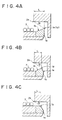
- an inclined surface 1k may be formed having upward gradient toward the hearth edge (lateral leading end) 1e on the furnace lateral end 1a as shown in Figs. 4A and 4B.
- the angle of the inclined surface 1k is not specifically restricted, in the hearth lateral end in a region (inner periphery side in general) different from the region (outer periphery side in general) where the pellets of reduced iron are discharged from the furnace by a discharging unit, the angle is preferably set at least angle of repose of the pellets 7 for example at least 25° so that the pellets 7 reaching the inclined surface may easily return into the original furnace.
- near the hearth edge 1e is previously cut obliquely (Fig. 4C) or given with radius R (not shown) to have a configuration for dispersing stress so that the hearth edge 1e may hardly have spalling.
- the carbon containing materials are not limited thereto but may include briquette shape, plate shape, nugget shape, powder mixture and the like.
- the hearth lateral end is formed by casting the alumina-based castable refarctories in the furnace as in experiments Nos. 1 and 2, in which the length of covering directly over the lateral end with the side wall lower end (overlapped length) is slightly longer than in experiment No. 2 and the depression angle is also slightly smaller than in experiment No. 2 (L is 200mm and ⁇ is 17° ), and further, in the side wall lower end is buried the cooling water pipe welded with the anchor plate.
- the hearth edge has only slight cracks which does not reach spalling and no damage is found in the side wall edge.
- the increase of sludge in the seal trough is reduced in a great amount.
- the cooling means is installed, spalling of the side wall edge is prevented and the effect of shielding radiant heat from the furnace inside is enabled to prevent spalling of the hearth edge, and as a result, the pellets and the like can be prevented from falling down to the seal trough.
- the overlapped length L and depression angle ⁇ have the same value as experiment No. 5 and an inclined surface with upward gradient toward the edge is formed at the most edge side of the hearth lateral end (horizontal length is 100mm and gradient is 30° ), in which other conditions are the same as in experiment Nos. 4 and 5.
- any of the hearth edge and the side wall edge is not damaged at all and the increase of sludge in the seal trough is not found almost at all.
- the side wall lower end of the hood covers over the lateral ends of the hearth upper surface so that the refractory of the lateral ends is not directly exposed to radiant heat from the furnace inside. Then, the hearth edge is not heat distorted and spalling thereof can be prevented. Also, since the cooling means is installed in the side lower end, heat distortion of the side wall edge can be moderated thereby preventing spalling in these portions.
- the lateral end has an inclined surface with upward gradient toward a lateral leading end, carbon containing materials do not fall down to the seal trough so that the effect of the invention according to claims 1 to 3 can be obtained without interfering rotation of the hearth.
- the refractory of the lateral end can be burned outside the furnace to have a sufficient degree of strength, by which the problem of low strength of the lateral end due to the insufficient burnig can be prevented so that spalling of the hearth edge can be prevented in a more effective manner.
Landscapes
- Engineering & Computer Science (AREA)
- Chemical & Material Sciences (AREA)
- Manufacturing & Machinery (AREA)
- Materials Engineering (AREA)
- Metallurgy (AREA)
- Organic Chemistry (AREA)
- Mechanical Engineering (AREA)
- General Engineering & Computer Science (AREA)
- Tunnel Furnaces (AREA)
- Manufacture Of Iron (AREA)
- Manufacture And Refinement Of Metals (AREA)
- Furnace Housings, Linings, Walls, And Ceilings (AREA)
Applications Claiming Priority (2)
| Application Number | Priority Date | Filing Date | Title |
|---|---|---|---|
| JP2000372876 | 2000-12-07 | ||
| JP2000372876A JP3553873B2 (ja) | 2000-12-07 | 2000-12-07 | 還元金属製造用回転式炉床炉及び還元金属の製造方法 |
Publications (3)
| Publication Number | Publication Date |
|---|---|
| EP1213362A2 true EP1213362A2 (de) | 2002-06-12 |
| EP1213362A3 EP1213362A3 (de) | 2003-01-08 |
| EP1213362B1 EP1213362B1 (de) | 2006-06-07 |
Family
ID=18842350
Family Applications (1)
| Application Number | Title | Priority Date | Filing Date |
|---|---|---|---|
| EP01310014A Expired - Lifetime EP1213362B1 (de) | 2000-12-07 | 2001-11-29 | Drehherdofen zur Erzeugung von reduziertem Metall und Verfahren zur Erzeugung von reduziertem Metall |
Country Status (12)
| Country | Link |
|---|---|
| US (1) | US6685466B2 (de) |
| EP (1) | EP1213362B1 (de) |
| JP (1) | JP3553873B2 (de) |
| KR (1) | KR100468248B1 (de) |
| CN (1) | CN1195077C (de) |
| AT (1) | ATE329063T1 (de) |
| AU (1) | AU781769B2 (de) |
| CA (1) | CA2364273C (de) |
| DE (1) | DE60120327T2 (de) |
| ES (1) | ES2266125T3 (de) |
| RU (1) | RU2217504C2 (de) |
| TW (1) | TW574373B (de) |
Cited By (1)
| Publication number | Priority date | Publication date | Assignee | Title |
|---|---|---|---|---|
| EP2243845A1 (de) * | 2003-04-09 | 2010-10-27 | Kabushiki Kaisha Kobe Seiko Sho | Verfahren zur Herstellung von reduziertem Metall mittels nachgebesserter Kohle |
Families Citing this family (12)
| Publication number | Priority date | Publication date | Assignee | Title |
|---|---|---|---|---|
| JP4256645B2 (ja) * | 2001-11-12 | 2009-04-22 | 株式会社神戸製鋼所 | 金属鉄の製法 |
| EP1553196B1 (de) * | 2002-10-18 | 2008-07-30 | Kabushiki Kaisha Kobe Seiko Sho | Ferronickel und verfahren zur herstellung von rohmaterial für die ferronickelverhüttung |
| JP4490640B2 (ja) * | 2003-02-26 | 2010-06-30 | 株式会社神戸製鋼所 | 還元金属の製造方法 |
| JP4531348B2 (ja) * | 2003-06-03 | 2010-08-25 | 大同特殊鋼株式会社 | 移動炉床炉の粉体材料供給装置 |
| JP4866195B2 (ja) * | 2005-10-11 | 2012-02-01 | 株式会社神戸製鋼所 | 回転炉床炉 |
| JP5403737B2 (ja) * | 2009-03-25 | 2014-01-29 | 新日鉄住金エンジニアリング株式会社 | 回転炉床炉 |
| EP2581151B1 (de) * | 2010-06-11 | 2015-05-06 | Diavac Limited | Lichtbogen-schmelzofenvorrichtung |
| JP6020262B2 (ja) * | 2013-03-05 | 2016-11-02 | 新日鐵住金株式会社 | スラグ処理用ホッパー |
| CN105021032A (zh) * | 2015-07-21 | 2015-11-04 | 石家庄新华能源环保科技股份有限公司 | 一种环形转底炉 |
| CN105627735A (zh) * | 2016-02-26 | 2016-06-01 | 四川鸿舰重型机械制造有限责任公司 | 用于生产三氧化二钒的还原窑 |
| CN110386429A (zh) * | 2019-07-15 | 2019-10-29 | 大庆同方电控设备有限公司 | 立体回环运行油管燃气加热炉 |
| CN110814359A (zh) * | 2019-10-18 | 2020-02-21 | 东北大学 | 一种使用煤矸石自热还原生产还原铁粉的方法 |
Family Cites Families (14)
| Publication number | Priority date | Publication date | Assignee | Title |
|---|---|---|---|---|
| FR803478A (fr) | 1936-03-14 | 1936-10-01 | Stewarts & Lloyds Ltd | Perfectionnement aux fours à sole tournante |
| DE1151823B (de) | 1960-05-16 | 1963-07-25 | Mannesmann Ag | Drehherdofen zum Waermen von Stahlbloecken |
| US3443931A (en) * | 1965-09-10 | 1969-05-13 | Midland Ross Corp | Process for making metallized pellets from iron oxide containing material |
| US4227875A (en) * | 1978-09-12 | 1980-10-14 | Calcimatic International Limited | Rotary hearth for calcining kiln |
| CH649096A5 (en) | 1981-11-11 | 1985-04-30 | Technomet Ag | Process and equipment for thermal metal production |
| US4578031A (en) | 1984-11-09 | 1986-03-25 | Midland-Ross Corporation | Dimensionally stable movable furnace hearth |
| US4622905A (en) * | 1985-03-04 | 1986-11-18 | International Metals Reclamation Co., Inc. | Furnacing |
| US4597564A (en) * | 1985-05-23 | 1986-07-01 | The International Metals Reclamation Company, Inc. | Rotary hearth |
| US4701214A (en) * | 1986-04-30 | 1987-10-20 | Midrex International B.V. Rotterdam | Method of producing iron using rotary hearth and apparatus |
| US5186741A (en) * | 1991-04-12 | 1993-02-16 | Zia Patent Company | Direct reduction process in a rotary hearth furnace |
| US5885521A (en) * | 1994-12-16 | 1999-03-23 | Midrex International B.V. Rotterdam, Zurich Branch | Apparatus for rapid reduction of iron oxide in a rotary hearth furnace |
| US5567224A (en) * | 1995-06-06 | 1996-10-22 | Armco Inc. | Method of reducing metal oxide in a rotary hearth furnace heated by an oxidizing flame |
| JP3304872B2 (ja) * | 1998-03-23 | 2002-07-22 | ミドレックス テクノロジーズ,インコーポレイテッド | 回転炉床式加熱炉内における酸化鉄の急速還元方法及び装置 |
| JP2001073020A (ja) * | 1999-09-07 | 2001-03-21 | Mitsubishi Heavy Ind Ltd | 還元鉄の製造装置 |
-
2000
- 2000-12-07 JP JP2000372876A patent/JP3553873B2/ja not_active Expired - Lifetime
-
2001
- 2001-11-20 US US09/988,521 patent/US6685466B2/en not_active Expired - Lifetime
- 2001-11-29 DE DE60120327T patent/DE60120327T2/de not_active Expired - Lifetime
- 2001-11-29 EP EP01310014A patent/EP1213362B1/de not_active Expired - Lifetime
- 2001-11-29 AT AT01310014T patent/ATE329063T1/de not_active IP Right Cessation
- 2001-11-29 ES ES01310014T patent/ES2266125T3/es not_active Expired - Lifetime
- 2001-11-30 TW TW90129637A patent/TW574373B/zh not_active IP Right Cessation
- 2001-12-05 CA CA002364273A patent/CA2364273C/en not_active Expired - Fee Related
- 2001-12-06 RU RU2001133276/02A patent/RU2217504C2/ru not_active IP Right Cessation
- 2001-12-06 AU AU97104/01A patent/AU781769B2/en not_active Ceased
- 2001-12-06 KR KR10-2001-0076886A patent/KR100468248B1/ko not_active Expired - Fee Related
- 2001-12-07 CN CNB01140454XA patent/CN1195077C/zh not_active Expired - Fee Related
Cited By (2)
| Publication number | Priority date | Publication date | Assignee | Title |
|---|---|---|---|---|
| EP2243845A1 (de) * | 2003-04-09 | 2010-10-27 | Kabushiki Kaisha Kobe Seiko Sho | Verfahren zur Herstellung von reduziertem Metall mittels nachgebesserter Kohle |
| US8790420B2 (en) | 2003-04-09 | 2014-07-29 | Kobe Steel, Ltd. | Method for producing reduced metal and slag containing oxidized nonferrous metal using an upgraded coal |
Also Published As
| Publication number | Publication date |
|---|---|
| ATE329063T1 (de) | 2006-06-15 |
| CN1360061A (zh) | 2002-07-24 |
| RU2217504C2 (ru) | 2003-11-27 |
| CA2364273A1 (en) | 2002-06-07 |
| US6685466B2 (en) | 2004-02-03 |
| JP2002180137A (ja) | 2002-06-26 |
| KR20020045556A (ko) | 2002-06-19 |
| JP3553873B2 (ja) | 2004-08-11 |
| EP1213362A3 (de) | 2003-01-08 |
| US20020123019A1 (en) | 2002-09-05 |
| AU9710401A (en) | 2002-06-13 |
| DE60120327D1 (de) | 2006-07-20 |
| KR100468248B1 (ko) | 2005-01-27 |
| AU781769B2 (en) | 2005-06-09 |
| TW574373B (en) | 2004-02-01 |
| ES2266125T3 (es) | 2007-03-01 |
| DE60120327T2 (de) | 2007-05-24 |
| EP1213362B1 (de) | 2006-06-07 |
| CA2364273C (en) | 2007-01-30 |
| CN1195077C (zh) | 2005-03-30 |
Similar Documents
| Publication | Publication Date | Title |
|---|---|---|
| EP1213362B1 (de) | Drehherdofen zur Erzeugung von reduziertem Metall und Verfahren zur Erzeugung von reduziertem Metall | |
| US6569223B2 (en) | Method of manufacturing molten metal iron | |
| US6511316B2 (en) | Method of operating a rotary hearth furnace | |
| CN100478454C (zh) | 制备金属铁的方法 | |
| US4597564A (en) | Rotary hearth | |
| EP1298224A1 (de) | Verfahren und Vorrichtung zur Herstellung von geschmolzenem Eisen durch Lichtbogenheizung mit niedrigem Verschleissindex | |
| RU2566698C2 (ru) | Устройство для плавки и рафинирования цветных металлов с примесями, в частности лома меди и/или меди с примесями, получаемой в результате обработки минералов | |
| EP1584693B1 (de) | Verfahren zur herstellung von metallischem eisen | |
| US4466827A (en) | Method for melting metals | |
| EP1939565B1 (de) | Drehherdofen | |
| EP0040440B2 (de) | Schachtofen, insbesondere die feuerfeste Konstruktion dessen Gestellbodens | |
| RU2125621C1 (ru) | Футеровка кожуха алюминиевого катодного электролизера | |
| JPH0532511Y2 (de) | ||
| JPH07268446A (ja) | 回転炉床式加熱炉での鋼片の載置方法及びその装置 | |
| AU2011203288A1 (en) | Rotary hearth furnace |
Legal Events
| Date | Code | Title | Description |
|---|---|---|---|
| PUAI | Public reference made under article 153(3) epc to a published international application that has entered the european phase |
Free format text: ORIGINAL CODE: 0009012 |
|
| 17P | Request for examination filed |
Effective date: 20011212 |
|
| AK | Designated contracting states |
Kind code of ref document: A2 Designated state(s): AT BE CH CY DE DK ES FI FR GB GR IE IT LI LU MC NL PT SE TR |
|
| AX | Request for extension of the european patent |
Free format text: AL;LT;LV;MK;RO;SI |
|
| PUAL | Search report despatched |
Free format text: ORIGINAL CODE: 0009013 |
|
| AK | Designated contracting states |
Kind code of ref document: A3 Designated state(s): AT BE CH CY DE DK ES FI FR GB GR IE IT LI LU MC NL PT SE TR |
|
| AX | Request for extension of the european patent |
Free format text: AL;LT;LV;MK;RO;SI |
|
| AKX | Designation fees paid |
Designated state(s): AT BE CH CY DE DK ES FI FR GB GR IE IT LI LU MC NL PT SE TR |
|
| 17Q | First examination report despatched |
Effective date: 20040924 |
|
| GRAP | Despatch of communication of intention to grant a patent |
Free format text: ORIGINAL CODE: EPIDOSNIGR1 |
|
| GRAS | Grant fee paid |
Free format text: ORIGINAL CODE: EPIDOSNIGR3 |
|
| GRAA | (expected) grant |
Free format text: ORIGINAL CODE: 0009210 |
|
| AK | Designated contracting states |
Kind code of ref document: B1 Designated state(s): AT BE CH CY DE DK ES FI FR GB GR IE IT LI LU MC NL PT SE TR |
|
| PG25 | Lapsed in a contracting state [announced via postgrant information from national office to epo] |
Ref country code: IT Free format text: LAPSE BECAUSE OF FAILURE TO SUBMIT A TRANSLATION OF THE DESCRIPTION OR TO PAY THE FEE WITHIN THE PRESCRIBED TIME-LIMIT;WARNING: LAPSES OF ITALIAN PATENTS WITH EFFECTIVE DATE BEFORE 2007 MAY HAVE OCCURRED AT ANY TIME BEFORE 2007. THE CORRECT EFFECTIVE DATE MAY BE DIFFERENT FROM THE ONE RECORDED. Effective date: 20060607 Ref country code: CH Free format text: LAPSE BECAUSE OF FAILURE TO SUBMIT A TRANSLATION OF THE DESCRIPTION OR TO PAY THE FEE WITHIN THE PRESCRIBED TIME-LIMIT Effective date: 20060607 Ref country code: FI Free format text: LAPSE BECAUSE OF FAILURE TO SUBMIT A TRANSLATION OF THE DESCRIPTION OR TO PAY THE FEE WITHIN THE PRESCRIBED TIME-LIMIT Effective date: 20060607 Ref country code: LI Free format text: LAPSE BECAUSE OF FAILURE TO SUBMIT A TRANSLATION OF THE DESCRIPTION OR TO PAY THE FEE WITHIN THE PRESCRIBED TIME-LIMIT Effective date: 20060607 Ref country code: NL Free format text: LAPSE BECAUSE OF FAILURE TO SUBMIT A TRANSLATION OF THE DESCRIPTION OR TO PAY THE FEE WITHIN THE PRESCRIBED TIME-LIMIT Effective date: 20060607 |
|
| REG | Reference to a national code |
Ref country code: GB Ref legal event code: FG4D |
|
| REG | Reference to a national code |
Ref country code: CH Ref legal event code: EP |
|
| REG | Reference to a national code |
Ref country code: IE Ref legal event code: FG4D |
|
| REF | Corresponds to: |
Ref document number: 60120327 Country of ref document: DE Date of ref document: 20060720 Kind code of ref document: P |
|
| PG25 | Lapsed in a contracting state [announced via postgrant information from national office to epo] |
Ref country code: SE Free format text: LAPSE BECAUSE OF FAILURE TO SUBMIT A TRANSLATION OF THE DESCRIPTION OR TO PAY THE FEE WITHIN THE PRESCRIBED TIME-LIMIT Effective date: 20060907 Ref country code: DK Free format text: LAPSE BECAUSE OF FAILURE TO SUBMIT A TRANSLATION OF THE DESCRIPTION OR TO PAY THE FEE WITHIN THE PRESCRIBED TIME-LIMIT Effective date: 20060907 |
|
| ET | Fr: translation filed | ||
| PG25 | Lapsed in a contracting state [announced via postgrant information from national office to epo] |
Ref country code: PT Free format text: LAPSE BECAUSE OF FAILURE TO SUBMIT A TRANSLATION OF THE DESCRIPTION OR TO PAY THE FEE WITHIN THE PRESCRIBED TIME-LIMIT Effective date: 20061107 |
|
| PG25 | Lapsed in a contracting state [announced via postgrant information from national office to epo] |
Ref country code: IE Free format text: LAPSE BECAUSE OF NON-PAYMENT OF DUE FEES Effective date: 20061129 |
|
| PG25 | Lapsed in a contracting state [announced via postgrant information from national office to epo] |
Ref country code: MC Free format text: LAPSE BECAUSE OF NON-PAYMENT OF DUE FEES Effective date: 20061130 |
|
| NLV1 | Nl: lapsed or annulled due to failure to fulfill the requirements of art. 29p and 29m of the patents act | ||
| REG | Reference to a national code |
Ref country code: CH Ref legal event code: PL |
|
| REG | Reference to a national code |
Ref country code: ES Ref legal event code: FG2A Ref document number: 2266125 Country of ref document: ES Kind code of ref document: T3 |
|
| PLBE | No opposition filed within time limit |
Free format text: ORIGINAL CODE: 0009261 |
|
| STAA | Information on the status of an ep patent application or granted ep patent |
Free format text: STATUS: NO OPPOSITION FILED WITHIN TIME LIMIT |
|
| 26N | No opposition filed |
Effective date: 20070308 |
|
| PG25 | Lapsed in a contracting state [announced via postgrant information from national office to epo] |
Ref country code: GR Free format text: LAPSE BECAUSE OF FAILURE TO SUBMIT A TRANSLATION OF THE DESCRIPTION OR TO PAY THE FEE WITHIN THE PRESCRIBED TIME-LIMIT Effective date: 20060908 |
|
| PG25 | Lapsed in a contracting state [announced via postgrant information from national office to epo] |
Ref country code: CY Free format text: LAPSE BECAUSE OF FAILURE TO SUBMIT A TRANSLATION OF THE DESCRIPTION OR TO PAY THE FEE WITHIN THE PRESCRIBED TIME-LIMIT Effective date: 20060607 |
|
| PGFP | Annual fee paid to national office [announced via postgrant information from national office to epo] |
Ref country code: LU Payment date: 20081203 Year of fee payment: 8 |
|
| PGFP | Annual fee paid to national office [announced via postgrant information from national office to epo] |
Ref country code: AT Payment date: 20081112 Year of fee payment: 8 Ref country code: ES Payment date: 20081216 Year of fee payment: 8 |
|
| PGFP | Annual fee paid to national office [announced via postgrant information from national office to epo] |
Ref country code: FR Payment date: 20081112 Year of fee payment: 8 |
|
| PGFP | Annual fee paid to national office [announced via postgrant information from national office to epo] |
Ref country code: GB Payment date: 20081126 Year of fee payment: 8 |
|
| GBPC | Gb: european patent ceased through non-payment of renewal fee |
Effective date: 20091129 |
|
| REG | Reference to a national code |
Ref country code: FR Ref legal event code: ST Effective date: 20100730 |
|
| PG25 | Lapsed in a contracting state [announced via postgrant information from national office to epo] |
Ref country code: AT Free format text: LAPSE BECAUSE OF NON-PAYMENT OF DUE FEES Effective date: 20091129 |
|
| PG25 | Lapsed in a contracting state [announced via postgrant information from national office to epo] |
Ref country code: FR Free format text: LAPSE BECAUSE OF NON-PAYMENT OF DUE FEES Effective date: 20091130 |
|
| PG25 | Lapsed in a contracting state [announced via postgrant information from national office to epo] |
Ref country code: GB Free format text: LAPSE BECAUSE OF NON-PAYMENT OF DUE FEES Effective date: 20091129 |
|
| REG | Reference to a national code |
Ref country code: ES Ref legal event code: FD2A Effective date: 20110328 |
|
| PG25 | Lapsed in a contracting state [announced via postgrant information from national office to epo] |
Ref country code: LU Free format text: LAPSE BECAUSE OF NON-PAYMENT OF DUE FEES Effective date: 20091129 |
|
| PG25 | Lapsed in a contracting state [announced via postgrant information from national office to epo] |
Ref country code: ES Free format text: LAPSE BECAUSE OF NON-PAYMENT OF DUE FEES Effective date: 20110315 |
|
| PG25 | Lapsed in a contracting state [announced via postgrant information from national office to epo] |
Ref country code: ES Free format text: LAPSE BECAUSE OF NON-PAYMENT OF DUE FEES Effective date: 20091130 |
|
| PGFP | Annual fee paid to national office [announced via postgrant information from national office to epo] |
Ref country code: TR Payment date: 20171121 Year of fee payment: 17 Ref country code: DE Payment date: 20171121 Year of fee payment: 17 |
|
| PGFP | Annual fee paid to national office [announced via postgrant information from national office to epo] |
Ref country code: IT Payment date: 20171123 Year of fee payment: 17 Ref country code: BE Payment date: 20170925 Year of fee payment: 17 |
|
| REG | Reference to a national code |
Ref country code: DE Ref legal event code: R119 Ref document number: 60120327 Country of ref document: DE |
|
| REG | Reference to a national code |
Ref country code: BE Ref legal event code: MM Effective date: 20181130 |
|
| PG25 | Lapsed in a contracting state [announced via postgrant information from national office to epo] |
Ref country code: IT Free format text: LAPSE BECAUSE OF NON-PAYMENT OF DUE FEES Effective date: 20181129 Ref country code: DE Free format text: LAPSE BECAUSE OF NON-PAYMENT OF DUE FEES Effective date: 20190601 |
|
| PG25 | Lapsed in a contracting state [announced via postgrant information from national office to epo] |
Ref country code: BE Free format text: LAPSE BECAUSE OF NON-PAYMENT OF DUE FEES Effective date: 20181130 |
|
| PG25 | Lapsed in a contracting state [announced via postgrant information from national office to epo] |
Ref country code: TR Free format text: LAPSE BECAUSE OF NON-PAYMENT OF DUE FEES Effective date: 20181129 |