EP1213373A2 - Procédé et installation pour le traitement d'articles dans un bain d'immersion - Google Patents
Procédé et installation pour le traitement d'articles dans un bain d'immersion Download PDFInfo
- Publication number
- EP1213373A2 EP1213373A2 EP01128993A EP01128993A EP1213373A2 EP 1213373 A2 EP1213373 A2 EP 1213373A2 EP 01128993 A EP01128993 A EP 01128993A EP 01128993 A EP01128993 A EP 01128993A EP 1213373 A2 EP1213373 A2 EP 1213373A2
- Authority
- EP
- European Patent Office
- Prior art keywords
- goods
- drive shaft
- horizontal
- immersion bath
- eccentric
- Prior art date
- Legal status (The legal status is an assumption and is not a legal conclusion. Google has not performed a legal analysis and makes no representation as to the accuracy of the status listed.)
- Withdrawn
Links
Images



Classifications
-
- C—CHEMISTRY; METALLURGY
- C25—ELECTROLYTIC OR ELECTROPHORETIC PROCESSES; APPARATUS THEREFOR
- C25D—PROCESSES FOR THE ELECTROLYTIC OR ELECTROPHORETIC PRODUCTION OF COATINGS; ELECTROFORMING; APPARATUS THEREFOR
- C25D17/00—Constructional parts, or assemblies thereof, of cells for electrolytic coating
- C25D17/06—Suspending or supporting devices for articles to be coated
-
- C—CHEMISTRY; METALLURGY
- C25—ELECTROLYTIC OR ELECTROPHORETIC PROCESSES; APPARATUS THEREFOR
- C25D—PROCESSES FOR THE ELECTROLYTIC OR ELECTROPHORETIC PRODUCTION OF COATINGS; ELECTROFORMING; APPARATUS THEREFOR
- C25D21/00—Processes for servicing or operating cells for electrolytic coating
- C25D21/10—Agitating of electrolytes; Moving of racks
Definitions
- the invention relates to a method for treating goods in an immersion bath, the goods being in a horizontal plane be moved in the immersion bath.
- the invention further relates to a device with a first drive to place goods arranged on a goods carrier to move a horizontal plane in an immersion bath.
- this task is carried out with specified features solved in that in addition to a first drive that moves the goods in the horizontal direction Immersion moves, a second drive is provided to the Goods to move vertically in the immersion bath.
- the goods in one Electroplating or paint bath not only horizontally, but also Moving vertically is an even mass transfer ensured at all points of the surface of the goods.
- the bathroom is optimally used that a uniform degree of separation and a uniformly galvanized or painted surface be achieved.
- the goods are placed in a horizontal direction along a Circle or an ellipse moves. It is particularly advantageous moving goods along hypocycloids. While of a complete cycle of horizontal movement for example at least one full vertical stroke Direction executed.
- the stroke is preferably for the vertical movement adjustable.
- the device according to the invention sees a first drive in front of the goods, which are arranged on a goods carrier are to be moved horizontally in the immersion bath.
- a second drive is provided, which the goods moved vertically in the immersion bath.
- the first and the second drive essentially consist of a horizontal drive shaft on which two eccentrics sit.
- the horizontal drive shaft drives a first and a second vertical drive shaft.
- the first bevel gear of the horizontal drive shaft engages in a bevel gear at the bottom of the first vertical drive shaft is attached while the second Bevel gear of the horizontal drive shaft in a bevel gear attacks that at the bottom of the second vertical wave is attached.
- the first driver is the first eccentric and the second driver from the second eccentric of the horizontal Drive shaft driven.
- the goods carrier with the goods is rotatably mounted on the arms of the runners.
- the vertical Drive shafts By turning the horizontal drive shaft, for example by means of an electric motor, the vertical Drive shafts rotated so that the arms of the runners one Carry out a circular movement.
- the goods carrier with the goods therefore also performs a circular movement, so that the goods are rotated in a circle in the immersion bath.
- the eccentrics move the two runners in vertical direction back and forth so that the goods carrier with the goods also perform a lifting movement.
- An embodiment of the device according to the invention provides before, on the arm of each runner a planet gear store that on the inner circumference or on the outer circumference of a Sun wheel rolls off.
- the sun gear can be arranged in a rotationally fixed manner be or be rotated.
- the end point of the arm on each planet gear therefore travels along one Hypozykloide.
- the goods carrier with the goods carries the same Movement out.
- the goods are therefore immersed in moved horizontally along a hypocycloid.
- the goods are moved in by means of the eccentric moved vertically back and forth in the immersion bath.
- Figure 1 shows a first embodiment of an inventive Device in elevation.
- the horizontal drive shaft 4 is mounted in two bearings 25 which are U-shaped on the web 26 Bearing blocks 18 are arranged.
- On the right and on the left leg 27 of the U-shaped bearing block 18 is one in vertically displaceable driver 11 or 12 attached.
- the drivers 11 and 12 are from a web 35 and two legs 33 and 34 U-shaped, the Leg 33 is longer than leg 34.
- Am lower end of the longer leg is a backdrop 17 incorporated in which an eccentric is mounted.
- In the Setting 17 of the longer leg 33 of the driver 11 is a eccentric 5 seated on the horizontal drive shaft 4 stored while in the backdrop 17 of the longer leg 33rd of the driver 12 on the horizontal drive shaft 4th seated eccentric 6 is mounted.
- a first Bearing 28 for a vertical drive shaft 7 and 8 On the right and on the left Leg 27 of the U-shaped bracket 18 is a first Bearing 28 for a vertical drive shaft 7 and 8 arranged.
- a second bearing 36 for the vertical Drive axes 7 and 8 is in the web 35 of the U-shaped driver 11 and 12 provided.
- On the top of the vertical Drive shaft 7 and 8 has a rotor 9 seated on web 35 the driver 11 and 12 rests.
- Runner 9 is in can be moved vertically but rotatably with the respective vertical drive shaft 7 and 8 connected.
- a longitudinal bore 37 is machined in the rotor 9, in which a stuck in the vertical drive axis 7 and 8 Driving pin 16 engages.
- an arm 10 At the top of the rotor 9 is an arm 10 is provided on which the goods carrier 1 is rotatable is stored.
- a bevel gear 23 At the lower end of the vertical drive axle 7 and 8 sits a bevel gear 23, each in one on the horizontal drive axis 4 seated bevel gear 24 engages.
- the a bevel gear 24 is at the left end of the horizontal drive shaft 4 attached while the other bevel gear 24 on the right End of the horizontal drive shaft 4 is arranged.
- the U-shaped Bearing block 18, which both the entire drive as well carries the product carrier is in a suitable place of a pelvis or attached to a tub.
- the U-shaped one Bearing block on the top of the basin or the tub be attached, in which there is a galvanic or a lacquer bath located.
- the goods to be provided with a protective layer are located z. B. in hanging on shopping cart 1 or are attached directly to the goods carrier 1, wherein they in the immersion bath is immersed.
- the horizontal drive shaft 4 can, for. B. with the Drive axis of an electric motor 19 connected, the Speed z. B. is controlled or regulated. Because the one on the horizontal drive shaft 4 seated eccentric 5 and 6 also rotate, the drivers 11 and 12 become vertical moves up and down, taking the two runners 9 with them also move up and down. Because the product carrier 1 on the Arms 10 of the rotor 9 is rotatably mounted, it will also moved up and down. The downward movement is caused by the Backdrop 17 positively controlled. The hanging on the goods carrier 1 Goods are thus moved up and down in the immersion bath.
- Bevel gears 24 are at the bottom of the vertical Drive shaft 7 and 8 attached bevel gears 23 driven, so the vertical drive shafts 7 and 8 as well rotate.
- the driver pin 16 which in the Longitudinal bores 37 of the rotor 9 are guided, rotate Runner 9 with the vertical drive shafts 7 and 8.
- the Bearing point of the goods carrier 1 on the arm 10 of the two runners 9 therefore performs a circular movement, which the on Join goods carrier 1 attached goods.
- FIG Device A second exemplary embodiment is shown in FIG Device according to the invention shown in elevation.
- the second embodiment differs from the first in that on the arms 10 the runner 9 instead of the Goods carrier each a planet gear 13 is rotatably mounted.
- On the upper end of the two drivers 11 and 12 is a internally toothed sun gear 14 attached to the inside Scope of the planet gear 13 rolls. Alternatively, it can externally toothed planet gear also on the outer circumference of an externally toothed Unroll sun gear.
- On the planet gear 13 is an arm 15 is attached, on which the goods carrier 1 is rotatable is stored.
- the vertical up and down movement takes place as in the first embodiment.
- the eccentrics 5 and 6 move the drivers 11 and 12 up and down, which take the runners 9 with the planet wheels 13 on which the goods carrier is rotatably mounted.
- the goods carrier 1 with the goods attached to it therefore makes the same upward movement as in the first embodiment.
- the runners 9 execute a circular movement as in the first exemplary embodiment, as a result of which the planet wheels 13 roll on the inner circumference of the two internally toothed sun wheels 14.
- the arm 15 of the planet gears 13 therefore moves along a hypocycloid and thus also the goods carrier 1 with the goods.
- the goods are therefore moved horizontally along a hypocycloid in the immersion bath, while at the same time making a vertical up and down movement.
- the second is the same as the first embodiment Embodiment at a suitable location on a basin or attached to a tub.
- Both the first and the second embodiment of the The device according to the invention can be designed such that the stroke of the vertical movement is adjustable.
- the horizontal and the vertical movement are so together combined that while driving through a complete cycle of horizontal movement at least one full stroke in the vertical direction.
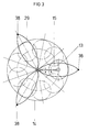
- Figure 3 are a sun gear 14 with a planet gear 13 and the arm 15 and the hypocycloid 29 passed through.
- FIG 4 is a plunge pool 21 with the attached Device according to the invention shown in elevation.
- the Dip pool 21 is filled with an electrolyte 22, in the Shopping carts 30 are immersed in which the galvanizing goods 2 are located, dashed in Figure 4 are drawn.
- the shopping baskets 30 hang on the goods carrier 1, which moves up and down in the vertical direction as well moved horizontally along a hypocycloid becomes.
- the goods carrier 1 is located above the plunge pool 21.
- the plunge pool 21 with the invention Device shown in plan view.
- the negative pole one DC voltage source 31 is connected to the goods carrier 1, the electrically conductive with the shopping carts 30 and the therein located goods 2 is connected, which represent the cathode.
- an anode bar 32 is arranged between the arranged in the middle of the plunge pool 21.
- the ions flow therefore between the anode bars 32 and the cathode.
- the method and the device according to the invention is particularly good for Electroplating or painting workpieces, the so-called Goods, suitable.
- the so-called Goods suitable.
- the immersion bath optimal use of the immersion bath is achieved.
Landscapes
- Chemical & Material Sciences (AREA)
- Engineering & Computer Science (AREA)
- Chemical Kinetics & Catalysis (AREA)
- Electrochemistry (AREA)
- Materials Engineering (AREA)
- Metallurgy (AREA)
- Organic Chemistry (AREA)
- Application Of Or Painting With Fluid Materials (AREA)
- Coating Apparatus (AREA)
- Electroplating Methods And Accessories (AREA)
- Coating With Molten Metal (AREA)
- Transmission Devices (AREA)
Applications Claiming Priority (2)
| Application Number | Priority Date | Filing Date | Title |
|---|---|---|---|
| DE10061226 | 2000-12-08 | ||
| DE10061226A DE10061226A1 (de) | 2000-12-08 | 2000-12-08 | Verfahren und Vorrichtung zur Behandlung von Waren in einem Tauchbad |
Publications (2)
| Publication Number | Publication Date |
|---|---|
| EP1213373A2 true EP1213373A2 (fr) | 2002-06-12 |
| EP1213373A3 EP1213373A3 (fr) | 2004-01-21 |
Family
ID=7666386
Family Applications (1)
| Application Number | Title | Priority Date | Filing Date |
|---|---|---|---|
| EP01128993A Withdrawn EP1213373A3 (fr) | 2000-12-08 | 2001-12-06 | Procédé et installation pour le traitement d'articles dans un bain d'immersion |
Country Status (3)
| Country | Link |
|---|---|
| US (1) | US20020071917A1 (fr) |
| EP (1) | EP1213373A3 (fr) |
| DE (1) | DE10061226A1 (fr) |
Cited By (1)
| Publication number | Priority date | Publication date | Assignee | Title |
|---|---|---|---|---|
| DE102005024771B4 (de) * | 2005-05-20 | 2008-08-21 | Hansgrohe Ag | Vorrichtung zum Behandeln von Waren |
Families Citing this family (4)
| Publication number | Priority date | Publication date | Assignee | Title |
|---|---|---|---|---|
| EP2813601A1 (fr) * | 2013-06-14 | 2014-12-17 | ATOTECH Deutschland GmbH | Dispositif pour déplacer un support de substrat pendant un dépôt de métal galvanique vertical et procédé de dépôt de métal galvanique vertical utilisant un tel dispositif |
| DE102018103808A1 (de) * | 2018-02-20 | 2019-08-22 | AP&S International GmbH | Vorrichtung zur stromlosen Metallisierung einer Zieloberfläche wenigstens eines Werkstücks |
| DE102018111331A1 (de) * | 2018-05-11 | 2019-11-14 | Ejot Gmbh & Co. Kg | Verfahren zur Beschichtung von Teilen in einem Tauch-Schleuderverfahren |
| CN113441342A (zh) * | 2021-07-21 | 2021-09-28 | 生命珍宝有限公司 | 一种钻石生产用的转移装置 |
Family Cites Families (4)
| Publication number | Priority date | Publication date | Assignee | Title |
|---|---|---|---|---|
| DE953759C (de) * | 1954-10-20 | 1956-12-06 | W Kampschulte & Cie Dr | Verfahren und Vorrichtung zum Bewegen der Werkstuecktraeger od. dgl. bei galvanischen Baedern |
| JPS62196398A (ja) * | 1986-02-21 | 1987-08-29 | Saatec Kk | スルーホールプリント基板の高速鍍金方法 |
| DE3905100A1 (de) * | 1989-02-20 | 1990-08-23 | Hans Henig | Verfahren und vorrichtung zum elektrolytaustausch vornehmlich in engen vertiefungen grossflaechiger werkstuecke |
| DE4133561C2 (de) * | 1991-10-10 | 1994-02-03 | Reinhard Kissler Gmbh | Verfahren und Vorrichtung zum Galvanisieren von Waren |
-
2000
- 2000-12-08 DE DE10061226A patent/DE10061226A1/de not_active Ceased
-
2001
- 2001-12-06 EP EP01128993A patent/EP1213373A3/fr not_active Withdrawn
- 2001-12-10 US US10/012,854 patent/US20020071917A1/en not_active Abandoned
Cited By (1)
| Publication number | Priority date | Publication date | Assignee | Title |
|---|---|---|---|---|
| DE102005024771B4 (de) * | 2005-05-20 | 2008-08-21 | Hansgrohe Ag | Vorrichtung zum Behandeln von Waren |
Also Published As
| Publication number | Publication date |
|---|---|
| EP1213373A3 (fr) | 2004-01-21 |
| US20020071917A1 (en) | 2002-06-13 |
| DE10061226A1 (de) | 2002-06-20 |
Similar Documents
| Publication | Publication Date | Title |
|---|---|---|
| DE4410477C1 (de) | Vorrichtung zur Oberflächenbehandlung von Fahrzeugkarosserien | |
| EP2684987A1 (fr) | Bain d'immersion avec une grille de support et un mécanisme élévateur | |
| DE202024100004U1 (de) | Freitragender Wendeförder- und Umlauffördersystem | |
| DE1006592B (de) | Verfahren und Vorrichtung zum Erzeugen von UEberzuegen durch Eintauchen der zu ueberziehenden Glasgegenstaende od. dgl. | |
| DE102024100024A1 (de) | Freitragender wendeförder- und umlauffördersystem | |
| DE10061226A1 (de) | Verfahren und Vorrichtung zur Behandlung von Waren in einem Tauchbad | |
| EP3498382A1 (fr) | Installation de traitement par immersion et procédé de traitement des objets | |
| DE2826655A1 (de) | Gleitschleifeinrichtung | |
| DE102010052367B4 (de) | Anordnung zur Oberflächenbehandlung und Verwendung dieser Anordnung | |
| DE3415218C2 (de) | Vorrichtung zum Entfernen von Schutzschichten | |
| DE822062C (de) | Verfahren zum Befoerdern von aus Blech bestehenden Koerpern, vorzugs-weise Fahrzeugkoerpern, durch eine Anlage zum Reinigen, Verhueten des Rostens, Grundieren und Bespruehen mit einer Farbfluessigkeit und Vorrichtung zur Durchfuehrung des Verfahrens | |
| DE2633179B2 (de) | Vorrichtung zur elektrophoretischen Beschichtung eines eine krummlinige Oberfläche aufweisenden elektrisch leitfähigen Werkstücks | |
| DE2708103A1 (de) | Vorrichtung zum behandeln von metallischen bauteilen | |
| DE802033C (de) | Vorrichtung zum Feuerverzinken von in mehreren Richtungen verformten Gegenstaenden, insbesondere Hohlkoerpern | |
| DE1107479B (de) | Vorrichtung zur Oberflaechenbehandlung von teilweise geschlossenen Hohlkoerpern im Tauchverfahren | |
| DE19950892A1 (de) | Vorrichtung zur Behandlung der Oberfläche von Gegenständen | |
| DE618656C (de) | Verfahren und Vorrichtung zum Herstellen von nahtlosen Tauchgummigegenstaenden | |
| DE2821192A1 (de) | Verfahren und anlage zum konservieren von teilen durch auftragen einer beschichtung im tauchverfahren | |
| DE725787C (de) | Anlage zum ununterbrochenen Haerten und Vergueten von Eisenteilen, insbesondere kleinen Werkstuecken | |
| DE2610625A1 (de) | Vorrichtung zur behandlung von werkstuecken in baedern | |
| DE2904176A1 (de) | Verfahren und vorrichtung zum konservieren von werkstuecken durch beschichten im tauchverfahren | |
| DE673520C (de) | Vorrichtung zum Herstellen von Baukoerpern, wie Saeulen, Kapitellen, Rohren | |
| DE102022122530A1 (de) | Behälterreinigungsmaschine zum Reinigen von Behältern und Verfahren zum Reinigen eines Behälters | |
| DE2222009C3 (de) | Vorrichtung zur Oberflächenbehandlung von Werkstücken, insbesondere von Kraftfahrzeugkarosserien oder Karosserieteilen | |
| DE2538585A1 (de) | Verfahren und vorrichtung zum polieren der innenflaeche eines laenglichen behaelters |
Legal Events
| Date | Code | Title | Description |
|---|---|---|---|
| PUAI | Public reference made under article 153(3) epc to a published international application that has entered the european phase |
Free format text: ORIGINAL CODE: 0009012 |
|
| AK | Designated contracting states |
Kind code of ref document: A2 Designated state(s): AT BE CH CY DE DK ES FI FR GB GR IE IT LI LU MC NL PT SE TR |
|
| AX | Request for extension of the european patent |
Free format text: AL;LT;LV;MK;RO;SI |
|
| PUAL | Search report despatched |
Free format text: ORIGINAL CODE: 0009013 |
|
| AK | Designated contracting states |
Kind code of ref document: A3 Designated state(s): AT BE CH CY DE DK ES FI FR GB GR IE IT LI LU MC NL PT SE TR |
|
| AX | Request for extension of the european patent |
Extension state: AL LT LV MK RO SI |
|
| RIC1 | Information provided on ipc code assigned before grant |
Ipc: 7B 65G 49/04 B Ipc: 7C 25D 17/06 B Ipc: 7C 25D 21/10 A |
|
| AKX | Designation fees paid | ||
| REG | Reference to a national code |
Ref country code: DE Ref legal event code: 8566 |
|
| STAA | Information on the status of an ep patent application or granted ep patent |
Free format text: STATUS: THE APPLICATION IS DEEMED TO BE WITHDRAWN |
|
| 18D | Application deemed to be withdrawn |
Effective date: 20040722 |