EP1213477A1 - Methode permettant de transformer la rotation d'un corps solide en une force de traction lineaire et faisant appel a un procede desequilibre directionnel, et dispositifs de mise en oeuvre de cette methode - Google Patents
Methode permettant de transformer la rotation d'un corps solide en une force de traction lineaire et faisant appel a un procede desequilibre directionnel, et dispositifs de mise en oeuvre de cette methode Download PDFInfo
- Publication number
- EP1213477A1 EP1213477A1 EP97927510A EP97927510A EP1213477A1 EP 1213477 A1 EP1213477 A1 EP 1213477A1 EP 97927510 A EP97927510 A EP 97927510A EP 97927510 A EP97927510 A EP 97927510A EP 1213477 A1 EP1213477 A1 EP 1213477A1
- Authority
- EP
- European Patent Office
- Prior art keywords
- axis
- rotation
- weights
- equal
- masses
- Prior art date
- Legal status (The legal status is an assumption and is not a legal conclusion. Google has not performed a legal analysis and makes no representation as to the accuracy of the status listed.)
- Ceased
Links
Images









Classifications
-
- F—MECHANICAL ENGINEERING; LIGHTING; HEATING; WEAPONS; BLASTING
- F03—MACHINES OR ENGINES FOR LIQUIDS; WIND, SPRING, OR WEIGHT MOTORS; PRODUCING MECHANICAL POWER OR A REACTIVE PROPULSIVE THRUST, NOT OTHERWISE PROVIDED FOR
- F03H—PRODUCING A REACTIVE PROPULSIVE THRUST, NOT OTHERWISE PROVIDED FOR
- F03H99/00—Subject matter not provided for in other groups of this subclass
-
- B—PERFORMING OPERATIONS; TRANSPORTING
- B60—VEHICLES IN GENERAL
- B60K—ARRANGEMENT OR MOUNTING OF PROPULSION UNITS OR OF TRANSMISSIONS IN VEHICLES; ARRANGEMENT OR MOUNTING OF PLURAL DIVERSE PRIME-MOVERS IN VEHICLES; AUXILIARY DRIVES FOR VEHICLES; INSTRUMENTATION OR DASHBOARDS FOR VEHICLES; ARRANGEMENTS IN CONNECTION WITH COOLING, AIR INTAKE, GAS EXHAUST OR FUEL SUPPLY OF PROPULSION UNITS IN VEHICLES
- B60K8/00—Arrangement or mounting of propulsion units not provided for in one of main groups B60K1/00 - B60K7/00
-
- B—PERFORMING OPERATIONS; TRANSPORTING
- B64—AIRCRAFT; AVIATION; COSMONAUTICS
- B64C—AEROPLANES; HELICOPTERS
- B64C29/00—Aircraft capable of landing or taking-off vertically, e.g. vertical take-off and landing [VTOL] aircraft
-
- B—PERFORMING OPERATIONS; TRANSPORTING
- B64—AIRCRAFT; AVIATION; COSMONAUTICS
- B64C—AEROPLANES; HELICOPTERS
- B64C39/00—Aircraft not otherwise provided for
- B64C39/001—Flying saucers
-
- B—PERFORMING OPERATIONS; TRANSPORTING
- B64—AIRCRAFT; AVIATION; COSMONAUTICS
- B64G—COSMONAUTICS; VEHICLES OR EQUIPMENT THEREFOR
- B64G1/00—Cosmonautic vehicles
- B64G1/22—Parts of, or equipment specially adapted for fitting in or to, cosmonautic vehicles
- B64G1/40—Arrangements or adaptations of propulsion systems
- B64G1/409—Unconventional spacecraft propulsion systems
-
- F—MECHANICAL ENGINEERING; LIGHTING; HEATING; WEAPONS; BLASTING
- F03—MACHINES OR ENGINES FOR LIQUIDS; WIND, SPRING, OR WEIGHT MOTORS; PRODUCING MECHANICAL POWER OR A REACTIVE PROPULSIVE THRUST, NOT OTHERWISE PROVIDED FOR
- F03G—SPRING, WEIGHT, INERTIA OR LIKE MOTORS; MECHANICAL-POWER PRODUCING DEVICES OR MECHANISMS, NOT OTHERWISE PROVIDED FOR OR USING ENERGY SOURCES NOT OTHERWISE PROVIDED FOR
- F03G3/00—Other motors, e.g. gravity or inertia motors
- F03G3/087—Gravity or weight motors
- F03G3/091—Gravity or weight motors using unbalanced wheels
Definitions
- the INVENTION is refered to the technical solution in the field of converting of the solid body's rotation into the linear, regulated and directed propulsion force.
- the linear motion of a body is originated as by the gravitation force, as, for example, by the difference in the body's density and the surrounding environment, existing, for example, in balloons or submerged apparatus/as due to the body's friction on the moving medium, for example, water's current on the drafting body, or the air on a sailboat.
- missile propeller which, however, may be of a limited use for consuming of a lot of expensive fuel, having engine force not controlled and the open fire, smoke and high noise level when operated.
- the aim of the previous invention was to create the linear propulsion force different in principle from the known modes of creation, as well as the propellers on this basis, that not interact with the surrounding medium, for mobile and transport apparatus, permitting, thus, their motion inside any moving or rarefied medium.
- the linear propulsion force is there created by absolutely new mode, i.e., by the converting of the rotation of a solid body into the linear propulsion force through the method of directed disbalance which parameters are controlled.
- the aim of the present invention is to develop the previous one.
- the essential what is used is the more developed usage of the rotation of a body.
- there the rotation of a body is used only to make distant from the body's axis the moving masses. Their approaching to the axis is done by the applied external force.
- the supplementary electric energy or other types of the applied forces or energy are needed.
- the energy of the rotation of a body is used as veil to make approaching the distant moving weights towards the body's axis, due to its conversion into such a force.
- the second difference is that the weights are approached to the axis by applying of the converted force to the proper body specifically at the points of a body equal for each weight.
- the force of reaction of a support - body that appears by this according to the 2-d Newton's law, is directed at the same or nearly the same side as the summed vector of the centrifugal forces of weights, arising by this the effectiveness of the methods and facilities And the proper body looks like it is approached to such weights that move away while the body rotates
- the appliance of forces at the equal for each weight points permits to sum the centrifugal forces and the forces of reaction of a support in more organized, effective and directed mode.
- the third difference is that the number of methods of creation of directed disbalance is arisen, for exempla, as there is a motion of moving weights along the orbits of different size which centers are displaced in one direction. By this, by two times is reduced the number of impulses of force during one rotation of a body and is widened the angle of sector of action of the centrifugal forces.
- the directed disbalance is created also by the masses of different value when the difference of masses' value is compensated by the reverse difference of sizes of the orbits of their motion.
- the invention describes the sophisticated vehicles where the facilities are mounted.
- the space is given to the new means of transportation in masses with previously unknown properties like "flying vehicle” and “flying motorcycle” with normal engines, capable of moving under control in the air due to the mounted inside facilities, as well as to the aerial and outerspace apparatus like "flying disc” and “flying coil” on the basis of facilities.
- the mode to convert the rotation of a solid body into the linear propulsion force, when upon the balanced body which axis is protected from rotation or produced with the possibility to rotate, are uniformly located one by one or in equal groups around the axis of rotation the equal masses, produced with the possibility of moving of each mass or its center of gravity away from the axis of rotation of a body and approaching to this axis by the equal trajectories, and with the rotation of a body the masses or its centers of gravity move away from the axis of rotation of a body under the influence of the force of inertia or the force of inertia in combination with the force, converted from the force of rotation of a body at the beginning of the trajectory of moving away, and then they are approached towards the axis by the action of the force, converted from the force of rotation of a body that makes support of a body or axis at the equal for each mass point or group of points, in cyclicity of one complete rotation of a body around the axis, having the masses rotated with the
- the mode of action it is the mechanical facility where on conventionally imovel basis is located the axis-support, produced with the possibility to rotate relatively this basis, having fixed upon the axis-support with the possibility to rotate relatively this one the balanced wheel-like or cone-like element on which equal radiant guides, located uniformly round the axis-support, are situated the equal weights, one on each guide, produced with the possibility to move along these guides, and also the eccentric and imovel axis-crank, mounted on the axis-support in parallel to this one, which eccentricity is regulated and on which is fixed the eccentric mechanism of group drive with the number of drive racks according to the number of weights on the element, each rack firmly fixed with the gear-wheel, situated upon the element in balance around the axis-support, at the beginning of each, radiant guide, and this wheel in alignment is connected to the sprocket, through which passes the closed driving chain, thrown over and tightened as well through the second sprocket, situated in balance on the element, at the end of each
- WP Racks-gears.
- the wobble plate The wobble plate. Cams, screw shaft.
- the wobble plate The wobble plate. Two weights on the screw shaft.
- the mechanical facility where on conventionally imovel base is located the drive shaft, capable to rotate, upon which in alignment and firmly is fixed the balanced wheel-like or cone-like element and on which opposite radiant guides are located per one equal weight, produced with the possibility to move along the guide, and also upon the element in parallel to the radiant guides is situated the balanced diametric screw shaft ,mounted upon the element with the possibility to rotate around its axis, in the middle of which in alignment and firmly is fixed the sprocket or the gear-wheel.
- each weight is equally chained to this screw shaft, and also upon the driving shaft between the base and the element is located the known mechanism of the wobble plate, which upper ring in perimeter is connected to the opposite edges the moving driving chain which is thrown over and tightened through the sprocket on the screw shaft, or to the upper ring of the wobble plate comes near the movel semi-gear wheel, fixed on the drive shaft longitudinally to it, with the possibility of having the limited angle of rotation, connected to the gear-wheel on the screw shaft, and the chaining of the weights with the screw shaft and(or) the chain with the sprocket or the semigear with the gear-wheel, preferably, is done in a such way that in position when the wobble plate is perpendicular to the drive shaft and both the ends of the chain or both edges of the semigear are distant equally from the element, the weights are kept in the middle of the guides at the equal distance from the axis of rotation of the element, or when there is the biggest slope of the wobble plate, and when the difference of
- the wobble plate with hydraulic drive The wobble plate with hydraulic drive.
- the wobble plate Chain with one weight.
- the mechanical facility with the wobble plate where on conventionally imovel base is located the drive shaft, capable to rotate, upon which in alignment and firmly is fixed the balanced wheel-like element, where on the diametrical guide is mounted the weight, produced with the possibility to move along this guide, and, more or less, the middle part of the weight is done as a rack, and the weight is chained with the gear-wheel-sprocket or the gearwheel, which is located upon the shaft with the possibility to rotate, as well as balanced, and on the shaft between the base and the element is situated the known mechanism of the wobble plate, which upper ring in perimeter is fixed to in moving position to the opposite edges, for example, by the ball hinges, the driving chain, which is thrown over and tightened through the sprocket, or joins movingly the semigear-wheel, fixed on the shaft in parallel to it and in balance with the possibility of having the limited angle of rotation, linked with the gear-wheel, having the chaining of the wheel with the rack on the weight preferably done in such a way that in
- the wobble plate with shears-like drive The wobble plate with shears-like drive.
- Masses of different orbits The mode where the equal masses move along different orbits in a such way that on the body is located the equal number of identical moving masses of two systems, situated so that the mass of one system is located diametrically opposite to the mass of the other system, and when the body rotates, the masses of different systems, rotated together with the body, or their centers of gravity, are approached to the axis with the assistance of the force, converted from the force of rotation of the body, or the attached force, that rests over the body at the points identical for the masses of one system, and are taken away from the axis of rotation under the action of the force of inertia or forces of inertia, in combination with the force, converted from the force of rotation of the body at the beginning of the trajectory of moving away, and by this, during the complete rotation of the body they move along the orbits identical for the masses of each system, different between systems, which centers are constantly displaced in one constant direction relatively the axis of rotation of the body, but at different distances from it, in a such
- the wobble plate The wobble plate. Two weights on the screw shaft.
- the mechanical facility with the wobble plate where on conventionally imovel base is located the drive shaft, capable to rotate, upon which in alignment and firmly is fixed the balanced wheel-like element, with mounted per one identical weight at the opposite radiant guides, produced with the possibility to move along the guide, as well as upon the element, in parallel to the radiant guides, is situated the balanced diametrical screw shaft, fixed upon the element with the possibility to rotate around its axis, in the middle of which, in alignment and firmly is mounted the sprocket or the gear-wheel, and each weight is chained to this screw shaft, and also on the drive shaft, between the base and the element, is located the known mechanism of the wobble plate, to which upper ring/to the opposite edges is fixed in moving position the driving chain, that is thrown over and tightened through the sprocket on the screw shaft, or to the upper ring of the wobble plate joins in moving position the semigear-wheel, fixed on the drive shaft longitudinally, with the possibility of having the limited angle of rotation, chained with the gear-
- the mode with two systems of masses which orbits of motion in each system are separated along the axis of rotation of the body in a such way that upon the body are located not less than two systems of masses, which trajectories and orbits of motion or the ones of centers of gravity are situated at some distance from the masses of the other system along the axis of rotation of the body, and the centers of orbits are constantly displaced in the constant direction relatively this axis, having the value of orbits as well as the value and direction of displacements of the center of orbits of the masses, not less than in one system of masses, as changeable ,when the body rotates or (and) rests, and owing to the mentioned, in the different parts of the body is created the linear propulsion force, which summed direction is changeable in space, and the body is capable to move along the complicated space trajectory.
- the wobble plate Racks, gears. Separated weights.
- the mechanical facility with two separated elements and wobble plates where on conventionally imovel base is located the drive shaft, capable to rotate, on which opposite ends, bulged out of the base, in alignment to the shaft and firmly are fixed two balanced wheel-like or cone-like elements where on equal radiant guides of each of them, uniformly situated around the shaft, are located, identical more or less for the element, the weights, one on each guide, produced with the possibility to move along these guides, and upon the shaft, at some distance from each element along the axis, between the base and each of the elements, are mounted two independent mechanisms of the wobble plates with slide racks, one for each element, and to the upper rings of the wobble plates are equally fixed by ball hinges the equal for the element racks, according the number of the weights on each of the element, and each rack uniformly and firmly is chained with the gear-wheel, situated on the corresponding element equally and balanced around the shaft , at the beginning of each radiant guide, and these gear-wheels of each element are also firmly and equally chained with the rack
- the wobble plate The wobble plate. Cams, screw shaft. Separated weights.
- the wobble plate Chain with one weight. Separated weights.
- the wobble plate Two weights on screw shaft. Separated weights.
- the mechanical facility with two separated elements and the wobble plates where on conventionally imovel base is located the drive shaft, capable to rotate, on which opposite ends, bulged out of the base, in alignment to the shaft and firmly are fixed two balanced wheel-like elements, having on two opposite radiant guides of each of them located the weight identical for, each of the elements, produced with the possibility to move along this guide, and also on each element in parallel to the radiant guides is situated the balanced diametrical screw shaft, fixed upon the element with the possibility to rotate round its axis, in the middle of which in alignment and firmly is located the sprocket or the gear-wheel, and each weight on the element is chained to the screw shaft, and upon the drive shaft, between the base and each element, are situated two independent mechanisms of the wobble plate, per one for each element, to the upper ring of each of them, to the opposite edges, is fixed in moving position the driving chain, thrown over and tightened through the sprocket on the screw shaft, or to the upper ring of the wobble plate joins movingly
- the mode that makes possible to create the propulsion force along the axis of the body with the assistance of two systems of masses are located uniformly or uniformly in identical groups around the axis of rotation at least two systems of masses, equal more or less in each system, which are uniformly situated around the axis of rotation in a such way that the mass of the one system uniformly alternates with the mass of the other system, and these masses or the centers of gravity are produced with the possibility to be approached towards the axis and be taken away from it along equal in each system trajectories in a way that when the body rotates, the masses, rotated together with the body, or their centers of gravity move along equal in each system orbits, which centers are constantly displaced in constant direction relatively the axis of rotation of the body, and with this, the shape, dimensions and displacement of the orbits of masses at least in one system are changeable when the body rotates and
- the mode that makes possible to create the propulsion force along the axis of the body with the assistance of two masses as follows: upon the balanced body are located at least two masses, which are situated uniformly round the axis of rotation, and these masses or their centers of gravity are produced with the possibility to be approached towards the axis and be taken away from it in a such way that when the body rotates, the masses, rotated together with the body, or their centers of gravity move each one along its orbit, which and their centers are constantly displaced in constant direction relatively the axis of rotation of the body, and by this, the shape and dimensions of the orbit, as well as the value and direction of displacement of the center of the orbit/at least of one mass, are changeable when the body rotates and (or) rests, and moreover, in case when the masses are equal, the trajectories and orbits of mass motion, or the ones of their centers of gravity are equal to each other and identically are inclined towards the axis of rotation of the body, the centers of orbits are equally displaced relatively the axis and are
- Cam mechanism Along the axis.
- the mechanical facility with the cam mechanism where there is the imovel axis-support with the imovel cam, and on the balanced cone-like element, situated on this axis-support with the possibility to rotate, is located the even number of the guides, inclined towards the axis, with the weight on each of them and the pushers and levers, being alternated, are connected with the driving kinematic pairs or chains oppositely the motion, permitting, when the element rotates, to create the double directed disbalance, which summed action is directed along the axis of rotation of the element.
- the wobble plate The wobble plate. Racks-gears. Along the axis.
- the wobble plate Cams-screw shaft. Along the axis.
- the character and the technical data of the facilities make possible their usage as the propulsive devices, or counterinertial facilities in different means of transportation, including the improvement of the known equipment and creation of the types of transport with early unknown properties.
- the all-wheel-drive vehicle where in the sphere of each wheel ace fixed the facilities and the rotating moment from the engine or engines of the vehicle instead of the drive wheels, or simultaneously with the drive wheels is transmitted in step to all facilities which ones while rotate create the propulsion force, that keep the vehicle moving, or create the counterinertial propulsion force, that brakes the movement, at the needed direction, and by this, the vehicle is guided by the common mechanisms of control, or the ones in combination with the additional facilities, making this vehicle to be capable of breaking ground and moving under control in the air.
- the motorcycle where at least in the sphere of wheels or wheels and the engine is located at least one facility, and in the sphere of the front wheel also it is equipped with the additional transmission of gear from the engine, and the rotating moment from the engine or engines instead of the drive wheel or simultaneously with the drive wheel is transmitted in step to all the facilities which ones while rotate create the propulsion force that keep moving the motorcycle, or create the counterinertial propulsion force that brakes the movement, at the needed direction, and by this, the moving of the moto is guided by the common for the moto mechanisms of control that relay also the commands to the facilities through normal mechanisms in combination with the additional mechanisms of control for the facilities, making this motorcycle to be capable of breaking ground and moving under control in the air.
- the aerial and outerspace apparatus of "flying disc” type where as the propulsive device are used two facilities, located in alignment, connected one to another with the possibility to rotate relatively one to another, and that are rotate to the opposite sides, between which ones or in the central part of which are located the power plant and the useful volume.
- the aerial and outerspace apparatus of "Flying reel” type where as the propulsive device are used two facilities with separated elements, connected in alignment one inside another with the possibility of relative rotation, or here is used one main facility, with separated elements, that is connected in alignment with two additional, equal and located mirror-like at its different sides facilities, produced with the possibility of relative rotation, and the facilities are rotated relatively each other oppositely, in a such way that their counterrotation is neutralized, and around the facilities there is a rigid construction, inside of which are located the power plant and the useful volume, while the shape and dimensions of the construction are determined by the shapes and dimensions of the propulsive device, as well as by the designation of a such apparatus.
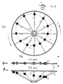
- Fig.1 The schematic diagram of implementation of the Directed Disbalance Mode upon the body in rotation: a) version with perpendicular to the axis of rotation trajectories of motion of masses; b) version with the tilted trajectories of the motion of masses.
- Fig.2 The diagram of changing of the linear speed and of centrifugal forces of moving masses.
- Fig.3. Epures of: a) centrifugal forces of masses; b) sum of centrifugal forces of masses and of forces of reaction of support (body).
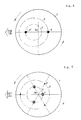
- Fig.4 The schematic diagram of implementing of the Directed Disbalance by equal and of different orbits masses.
- Fig.5. The schematic diagram of implementing of the Directed Disbalance by masses of different values and different orbits.
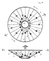
- Fig.6 The schematic diagram of attaching to the body the longitudinal motion with two systems of moving masses that move along the inclined (tilted) trajectories.
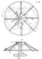
- Fig.8 The facility with the eccentric axis-crank for the propulsion force along the axis.
- Fig.10. The facility with the imovel cam and several weights for the propulsion force along the axis.
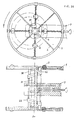
- Fig.11 The facility with the wobble plate and driving racks.
- Fig.12. The facility with the wobble plate and driving racks for the propulsion force along the axis.
- Fig.13 The facility with two wobble plates, driving racks and separated elements.
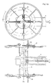
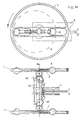
- Fig.14 The facility with the wobble plate and driving cams on the screw shafts.
- Pig.15 The facility with the wobble plate and driving cams on the screw shafts for the propulsion force along the axis.
- Fig.16 The facility with two wobble plates, driving cams on the screw shafts and separated elements.
- Fig.17 The facility with the wobble plate, driving chain and one weight.
- Fig.18 The facility with the wobble plate, driving chain and separated elements with one weight on each element.
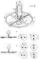
- Fig.19 The facility with the wobble plate and two weights on the screw shaft.
- Fig.20 The facility with two wobble plates and screw shafts upon the separated elements.
- Fig.21 The facility with the wobble plate and shears-like drive.
- Fig.22 The facility with the wobble plate and hydraulic drive.
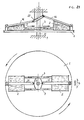
- Fig.23 The flying vehicle.
- Fig.24 The flying motorcycle.
- Fig.25 The vehicle with the facility at the bottom.
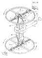
- Fig.26 The flying apparatus of "Flying disc” type.
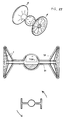
- Fig.27 The flying apparatus of "Flying reel” type.
- the axis of rotation body I (Fig.1), which axis Ao is protected from rotation or is produced with the possibility to rotate, are located uniformly or uniformly in equal groups around the axis of rotation Ao the equal masses, produced with the possibility of moving away of each mass or of its center of gravity from the axis of rotation of the body Ao and of approaching to this axis along the equal trajectories 3, and when the body 1 rotates, the masses 2 or their centers of gravity are moved away from the axis of rotation Ao of the body 1 under the influence of the force of inertia, or the force of inertia in combination with the force, converted from the force of rotation of the body at the beginning of the trajectory of moving away, and then, they are approached to the axis Ao under the influence of the force, converted from the force of rotation of the body Ao, that rests upon the body I or the axis Ao in identical for each mass 2 point or group of points, in cycle during the complete
- the weights kept when the body rotates in the interval between extremely near to the axis and extremely distant from the axis points of the orbit, are balancing each other at the opposite sides of the axis, eliminating the non-productive lateral beating and attaching to the propulsive force the perfect linear direction.
- the angle of action of the propulsive force is narrowed, the number of impulses of force, with the equal speed of rotation, is enlarged, and the value of force is increased due to the summing of vectors of centrifugal forces and forces of reaction of support of all the weights. All these attaches to the propulsive force more smoothless and effectiveness.
- the linear propulsive force capable of moving the rotated body, is created in the presence of such value of masses, dimensions of orbits of masses, value of displacement of the center of orbits relatively the axis of rotation of the body, as well as of the speed of rotation of the body, when the summed vector of centrifugal forces of all moving masses, that influence simultaneously upon the body, and as well the forces of reaction of support, is superior of the values of forces of inertia, friction and, or of gravity, that influence upon the body, and this difference, i.e. the linear propulsive force, can be changed by changing of any of the mentioned values.
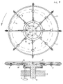
- the calculations are proved by the acting experimental facility (Fig.14).
- the directed disbalance can be created and by the unique moving mass upon the body. For this, the mass, when the body rotates, is moved in a such way that when the mass approaches to the axis of rotation, its center of gravity preferably coincides with the axis. Moreover, this happens, when the mass is approached towards the axis once during the rotation of the body at the extreme point of approaching, and then is taken away to the opposite side, or when the mass is approached to the axis twice during the rotation of the body, making it to pass each time through the axis to the opposite towards the axis side of the body. In this case the angle of the directed disbalance is reduced twice and the body is less subjected to the non-productive lateral vibrations.
- the directed disbalance is created by only one moving mass and also with the assistance of the imovel counterweight, located upon the body oppositely the mass, balancing the mass at one of the points of its trajectory, preferably at the middle one. Practically this is the directed disbalance upon the disbalanced body. Moreover, in the moment of the biggest moving away from the axis the moving mass influences on the body with the bigger centrifugal forces in the middle of the trajectory the centrifugal forces of the mass and of the counterweight are balanced, and in the moment of approaching of the mass towards the axis of the body the bigger is terned to be the value of the centrifugal force of the imovel counterweight. Thus, the summed vector of the centrifugal forces is always directed towards one side of the axis.
- the directed disbalance can be created with the assistance of the masses of variable value in a such way that upon the body are located equal masses, which value (Fig.21) is equally changed, and when the body 1 rotates, these masses 2 are in tern increased until the biggest values in the constant relatively the axis of rotation Ao of the body 1 sector of the orbit, and then are reduced until the minor values in the diametrically opposite sector of the orbit, and again are increased until the biggest values in the previous sector of the orbit, in cycle, during the complete rotation of the body I around the axis Ao due to the flowing of the substance from one mass 2 into the other, or flowing of the substance from each mass 2 into the general and balanced relatively the axis collector, and back, under the influence of applied force to reduce each mass 2, converted from the force of rotation of the body 1, or any other external force, that rests upon the body 1 or the axis Ao at the equal for each mass 2 points.
- the body 1 (Fig.4) is situated the equal number of the identical moving masses 2 and 2' of two systems, located in a such way that the mass 2 of one system is mounted diametrically opposite to the mass 2' of the other system, and when the body 1 rotates, the masses 2 and 2' of different systems, rotated together with the body 1, or their centers of gravity, are approached to the axis Ao with the assistance of the force, converted from the force of rotation of the body 1 or from the applied force, that rests upon the body 1 at equal for masses 2 and 2' of one system points, and are taken away from the axis of rotation Ao under the influence of the force of inertia or forces of inertia, in combination with the force, converted from the force of rotation of the body 1 at the beginning of the trajectory of moving away in a such way that during the complete rotation of the body 1, they move along the equal for the masses of each system orbits 4 and 4', different between systems, which centers are constantly displaced in one constant direction relatively the axis of rotation Ao of
- the balanced body 1 (Fig.5) is located the even number of masses 2 and 2'of two systems, equal in each system, but different between systems, situated upon the body I in a such way that the mass of one system is mounted diametrically opposite to the mass of the other system, and when the body 1 rotates, the masses 2 and 2', rotated together with the body 1, or their centers of gravity, are approached to the axis of rotation Ao of the body 1 by the force, converted from the force of rotation of the body, that rests upon the body or the axis at equal for masses of each system points, and the masses are taken away from the axis under the action of forces of proper inertia, so that the masses of different systems or their centers of gravity move during the complete rotation of the body along, the equal in each system, but different between systems, orbits 4 and 4', which centers in both systems are constantly displaced in one constant, relatively the axis of rotation Ao of the body 1, direction, so that the orbit 4 of each bigger mass 2 is less than the orbit 4' of each minor
- the body 1 Upon the body 1 (Pig. 13) are located at least two systems of the masses 2 and 2', which trajectories 3 and 3' and orbits 4 and 4' of motion, or of motion of the centers of gravity are situated at some distance from the masses of the other system along the axis of rotation Ao of the body 1, and the centers of the orbits are constantly displaced at the constant direction relatively this axis Ao, and by this, the value of the orbits 4 and 4', as well as the value and direction of displacements of the center of orbits of masses 2 and 2', at least, in one system of masses, are changeable when the body rotates 1 or, and rests, so due to the mentioned, in different parts of the body 1 is created the linear propulsion force, which summed direction is changeable in space, and the body 1 is capable to move along the complicated space tajectory.
- the mass 2 which is done, or which center of gravity is done with the possibility to move away from the axis Ao of the body 1 and to approach to the axis Ao along the constant trajectory, and when the body rotates 1, the mass 2 or its center of gravity is moved from the axis Ao under the influence of the force of inertia, or the force of inertia in combination with the force, converted from the force of rotation of the body 1, or any other applied force at the beginning of the trajectory of moving away, and then the mass 2 or its center of gravity is approached to the axis Ao under the force, converted from the force of rotation of the body 1 or any other applied force/that rests upon the body 1, or upon the axis Ao, in cycle during the complete rotation of the body 1, or the mass 2 or its center of gravity are taken away, returned into the previous position,
- the variety of the previous is the mode where the trajectory of motion of the moving mass 2 upon the body 1 does not intercross the axis Ao of rotation of the body 1, and upon the body 1 is located in addition the imovel counterweight 5, situated oppositely to the mass 2, in a such way and of a such weight that it balances the mass 2 at any point of its trajectory 4, preferably located in the middle of the trajectory 3, and produced with the possibility to change the eccentricity C, and due to the counterweight 5 when the body 1 rotates, is narrowed the sector of action of the directed disbalance, and when the eccentricity C of the counterweight 5 changes, the direction of such a sector is changed.
- the directed disbalance by analogy, is created with the assistance of one mass of varying value in a such way that the value of the mass is changed, for example, by flowing of the substance of the mass into the balanced relatively the axis of the body collector and back, and when the body rotates, the mass is reduced until the minor value in the constant relatively the axis of rotation sector of the orbit, by the force, converted from the force of rotation of the body, that rests upon the body, and then, is increased until the biggest value due to the flowing of the substance of the mass under the action of the force of inertia in the diametrically opposite sector of the orbit, and then, again is reduced until the minimum value in the previous sector of the orbit by the force, converted from the force of rotation of the body, in cycle, during the complete rotation of the body around the axis.
- the body I Upon the body I (Fig.19) are located two equal masses 2, which trajectories and orbits 4 of motion, or of motion of their centers of gravity are situated at some distance one from another along the axis of rotation Ao of the body 1, and the centers of the orbits are constantly displaced in constant for each mass 2 direction relatively this axis Ao, and with this, the value of the orbit 4 as well as the value and direction of displacement of the center of the orbit 4 at least of one mass 2 are changeable when the body 1 rotates and (or) rests, and due to this in different parts of the body 1 is created the linear propulsion force, which summed direction is changeable in space, and the body 1 is capable of moving along the complicated space trajectory.
- the imovel axis-support 8 Upon the base 7 (Fig.8) is located the imovel axis-support 8, and on the cone-like element 1 is situated the even number of the inclined towards the axis Ao guides 3 with the weight 2 on each of them, and driving racks 16, being alterated, are connected with the driving kinematic pairs or chains 10 oppositely the motion, and this permits when the element I rotates, to create the double directed disbalance, which summed action is directed along the axis of rotation Ao of the element 1.
- the axis-support 8 On conventionally imovel base 7 (Fig.9) is located the axis-support 8, produced with the possibility to rotate relatively this base 7, and upon the axis-support 8 is situated with the possibility to rotate relatively it the balanced wheel-like or cone-like element 1, on which equal radiant guides3, uniformly located around the axis-support 8, are fixed equal weights 2, one on each guide 3, produced with the possibility to move along them, and on the axis-support 8 is mounted the known cam mechanism with the imovel and convex cam 18 that possesses the identical pushers 16 or levers according to the number'of the weights 2, and each of them is equally and firmly chained or connected with the corresponding equal gear-wheel 14, which are located upon the element 1 uniformly and in balance, at the beginning of each radiant guide 3, and this gearwheel 14 in alignment is chained in pair with the sprocket 17, through which is thrown over the closed driving chain 10, thrown over and tightened through the second sprocket 17, situated upon the element in balance, at the end of each
- Cam mechanism Along the axis.
- the imovel axis-support 8 Upon the base 7 (Fig.10) is situated the imovel axis-support 8, and on the cone-like element 1 is located the even number of the inclined to the axis guides 3 with the weight 2 on each of them and pushers 16 or levers, being alternated, are connected with the driving kinematic pairs or chains 10 oppositely to the motion, and thus permitting, when the element 1 rotates, to create the double directed disbalance, which summed action is directed along the axis Ao of rotation of the element 1.
- the wobble plate The wobble plate.
- Racks-gears The wobble plate.
- the wobble plate The wobble plate. Racks-gears. Along the axis.
- the wobble plate Racks-gears. Along the axis. Two wobble plates.
- the wobble plate The wobble plate. Racks-gears. Separated weights.
- the wobble plate Cams-screw shaft.
- the wobble plate Cams-screw shaft. Along the axis.
- the wobble plate Cams-screw shaft. Separated weights.
- the wobble plate Chain with one weight.
- the wobble plate Chain with one weight. Separated weights.
- the wobble plate Two weights on a screw shaft.
- the wobble plate Two weights on the screw shaft. Separated weights.
- the weights 2 are kept in the middle of the guides, at equal distance from the axis of rotation Ao of the element, and when the drive shaft 11 rotates, the driving chains 10, or the gear-wheels 28,in cycle moved by the wobble plates 22, rotate in reverse the screw shafts 27 of the elements 1, that by the reciprocating motion move the weights 2 along the guides in a such way that during the complete rotation of the elements 1, the weights 2, rotated together with the elements 1, move on each element 1 along the closed orbits 4, which centers are constantly displaced in constant direction relatively the axis of rotation Ao, thus, creating the double directed disbalance at the different ends of the shaft 11, attaching to it the linear propulsion force, and moreover, in case of the second preferable chaining of the weights 2 with the screw shaft 27 or (and) the chain 10 with the sprocket 17, or the semiwheel 28 with the gear-wheel 14, the weights 2 of each element 1 rotate along the different orbits 4, and when the directions and angles of slope of the wobble plates 22 are changed, are changed the direction and the value
- the sphere of the implementation of the invention is, as follows: in the terrestrial, aquatic, submerged, aerial, outerspace and universal mobile and transport apparatus as the propulsive device or counterinertial facility, as well as in the moving parts of the vehicles and mechanisms.
- the character and technical properties of the facilities enable to make use of them as the propulsive devices, or counterinertial facilities in different means of transportation, including in developing of the known machinery and creation of new types of the transport in masses with the early unknown properties.
- the flying vehicle The flying vehicle.
- the all-wheel-drive vehicle (Fig.23) where in the sphere of each wheel, in parallel or under the angle to it, in mirror-like position at different ends of the axis, are fixed at least per one facility 1, equal on the axis, located with the possibility to rotate relatively the corresponding wheel, or upon the axis is mounted the facility 1, located with the possibility to rotate relatively the corresponding wheels, which clearance limits do not bulged out of the lower clearance limits of the wheels, and the angles of turning, at least some of them, are changed by steering controls equally and (or) in step with the turning angles of the steering wheels, or the turning angles are not changed by the steering controls, and the rotating moment from the engine or engines of the vehicle instead of the driving wheels, or simultaneously with the driving wheels is transmitted in step to all facilities 1, which while rotate, create the propulsion force, that moves the vehicle, or create the counterinertial force, that brakes the motion, in the needed direction, and by this, the parameters of the directed disbalance of the facilities 1, with which assistance is controlled the motion of the vehicle, are changed through the
- the flying motorcycle The flying motorcycle.
- the motorcycle (Fig.24) where in the sphere of the engine as well as in the sphere of each wheel, in parallel to them, or under the angle to them, or at least in the sphere of each wheel, is fixed at least per one facility 1, located with the possibility to rotate relatively the corresponding wheel, which clearance limits do not bulged out of the lower clearance limits of the wheels, and the turning angle at least of the front facility 1 is changed equally, or in step with the turning angle of the steering wheel, or the turning angle of the facilities 1 is not changed by the steering controls, and in the sphere of the front wheel also there is the additional transmission of gear from the engine or engines, and the rotating moment from the engine or engines instead of the driving wheel, or simultaneously with the driving wheel is transmitted in step to all the facilities 1, which, while rotate, create the propulsion force that moves the motorcycle, or create the counter-inertial propulsion force, that brakes its motion, in the needed direction, and by this, the parameters of the directed disbalance of the facilities 1, with which assistance the motion of the motorcycle is controlled, are changed through the simple for motorcycle
- the vehicle with the facility at the bottom is the vehicle with the facility at the bottom.
- the vehicle where as the main or additional propulsive device is used at least one facility 1, mounted in the sphere of the bottom, or where is used the facility 1, mounted in the center of the vehicle in a such way that the drive shaft is located vertically , and the elements are situated in the sphere of the bottom and top, and the rotating moment from the engine is transmitted instead of the wheels to the facility 1, or simultaneously with the driving wheels to the facility 1, which, when rotates, creates the propulsion force, that moves the vehicle, or that create the counterinertial propulsion force, that brakes the motion, in the needed direction, and by this, the parameters of the directed disbalance of the facility 1, are changed through the simple steering mechanisms of the vehicle with the additional drives of the of the step action for the facilities, or the parameters of the facilities 1 are changed by the independent steering mechanisms for the facilities
- the flying disc The flying disc.
- the aerial and outerspace apparatus of "flying disc” type (Fig.26) where as the propulsive device are used two facilities I, located in alignment, connected one to another with the possibility to rotate relatively each other, and that are rotate to the opposite sides, between which ones or in the central part of which are located the power plant 29 and the useful volume, and all these are enclosed into the streamlined hull 30, which shape and dimensions are determined by the shape and diminution of the propulsive device.
- the flying reel The flying reel.
- the aerial and outerspace apparatus of "flying reel” type (Fig.27) where as the propulsive device are used two facilities with separated elements, connected in alignment one inside another with the possibility of relative rotation, or here is used the facility 1 with the separated elements, connected in alignment with two equal and located mirror-like at its different sides facilities 1, produced with the possibility of relative rotation, and the facilities 1 are rotated relatively each other oppositely, in a such way that their counterrotation is neutralized, and around the facilities 1 there is a rigid construction 31, inside of which are located the power plant 29 and the useful volume, while the shape and dimensions of the construction 31 are determined by the shapes and dimensions of the propulsive device, as well as by the designation of a such apparatus.
Landscapes
- Engineering & Computer Science (AREA)
- Chemical & Material Sciences (AREA)
- Combustion & Propulsion (AREA)
- Aviation & Aerospace Engineering (AREA)
- Mechanical Engineering (AREA)
- General Engineering & Computer Science (AREA)
- Remote Sensing (AREA)
- Transportation (AREA)
- Transmission Devices (AREA)
- Nitrogen And Oxygen Or Sulfur-Condensed Heterocyclic Ring Systems (AREA)
Applications Claiming Priority (3)
| Application Number | Priority Date | Filing Date | Title |
|---|---|---|---|
| RU96110479/06A RU96110479A (ru) | 1996-05-24 | Способ преобразования вращения твердого тела в линейную тяговую силу "методом направленного дисбаланса, часть 2", а также устройства для использования этого способа и применение таких устройств | |
| RU96110479 | 1996-05-24 | ||
| PCT/RU1997/000163 WO1997045639A1 (fr) | 1996-05-24 | 1997-05-23 | Methode permettant de transformer la rotation d'un corps solide en une force de traction lineaire et faisant appel a un procede desequilibre directionnel, et dispositifs de mise en oeuvre de cette methode |
Publications (2)
| Publication Number | Publication Date |
|---|---|
| EP1213477A1 true EP1213477A1 (fr) | 2002-06-12 |
| EP1213477A4 EP1213477A4 (fr) | 2009-07-15 |
Family
ID=20181027
Family Applications (1)
| Application Number | Title | Priority Date | Filing Date |
|---|---|---|---|
| EP97927510A Ceased EP1213477A4 (fr) | 1996-05-24 | 1997-05-23 | Methode permettant de transformer la rotation d'un corps solide en une force de traction lineaire et faisant appel a un procede desequilibre directionnel, et dispositifs de mise en oeuvre de cette methode |
Country Status (3)
| Country | Link |
|---|---|
| EP (1) | EP1213477A4 (fr) |
| AU (1) | AU3195897A (fr) |
| WO (1) | WO1997045639A1 (fr) |
Cited By (10)
| Publication number | Priority date | Publication date | Assignee | Title |
|---|---|---|---|---|
| WO2004061335A1 (fr) * | 2002-12-27 | 2004-07-22 | Siegbert Pietschmann | Dispositif d'entrainement et procede pour faire fonctionner ce dispositif d'entrainement |
| EP1510458A1 (fr) * | 2002-07-17 | 2005-03-02 | Norman V. Robinson | Generateur de poussee verticale pour la levitation d'une plateforme |
| WO2008010257A3 (fr) * | 2006-07-18 | 2008-03-13 | Antonio Romano | appareil avec masses excentriques rotatives pour développer des forces d'inertie unidirectionnelles |
| FR2911655A1 (fr) * | 2007-01-19 | 2008-07-25 | Roger Eisenberg | Dispositif mecanique generateur de mouvement |
| DE102007033200A1 (de) * | 2007-07-17 | 2009-07-02 | Kunst, Ernst K. | Vorrichtung und Verfahren zur teilweisen oder vollständigen Aufhebung des Gewichts von materiellen Objekten sowie zur Erzeugung des Auftriebs und Vortriebs von Boden-, Wasser-, Luft- und Raumfahrzeugen (Hubkreisel oder -rotor) |
| WO2011041882A1 (fr) * | 2009-10-06 | 2011-04-14 | Boguslaw Rudzik | Moteur centrifuge et véhicules équipés de celui-ci |
| EP2341602A1 (fr) * | 2009-12-30 | 2011-07-06 | Dmitryi Lysyuk | Actionneur basé sur la force centrifuge créée par des objets magnétiques en rotation |
| WO2011158048A3 (fr) * | 2010-06-17 | 2012-12-27 | Grigorios Karamitsos | Mécanisme de propulsion de l'impulsion inertielle double |
| KR20240040560A (ko) * | 2022-09-21 | 2024-03-28 | (주)중앙소방이앤지 | 드론 |
| WO2025171433A1 (fr) * | 2024-02-12 | 2025-08-21 | Green Gregory John | Dispositif de focalisation de force |
Families Citing this family (7)
| Publication number | Priority date | Publication date | Assignee | Title |
|---|---|---|---|---|
| RU2263819C2 (ru) * | 2003-06-16 | 2005-11-10 | Баврин Геннадий Иванович | Центробежный инерционный движитель |
| RU2282054C2 (ru) * | 2004-03-23 | 2006-08-20 | Александр Иванович Михайлов | Способ передвижения транспортного средства и устройство для его осуществления |
| GB2498367A (en) * | 2012-01-11 | 2013-07-17 | Derek Edward Bird | Mass rotating with changing radius to produce non-constant centripetal force |
| CH708094A2 (fr) * | 2013-05-27 | 2014-11-28 | Alec Blanchard | Procédé pour créer une force propulsive. |
| CN111717420B (zh) * | 2020-07-21 | 2023-08-22 | 哈尔滨工业大学 | 压紧机构精准限位展开装置及展开限位方法 |
| WO2023144843A1 (fr) * | 2022-01-31 | 2023-08-03 | Torkzaban Mostafa | Système fermé de liquide servant à convertir une force centrifuge en une force linéaire |
| CN118424558B (zh) * | 2024-07-05 | 2024-10-01 | 济南轻骑铃木摩托车有限公司 | 一种摩托车发动机生产检测装置 |
Family Cites Families (53)
| Publication number | Priority date | Publication date | Assignee | Title |
|---|---|---|---|---|
| SU5888A1 (ru) * | 1925-11-09 | 1928-07-31 | В.Б. Вейнберг | Приспособление дл сообщени прыжка самодвижущемус экипажу |
| US2966317A (en) * | 1958-02-03 | 1960-12-27 | Autocopter Corp Of America | Paddle wheel sustained aircraft |
| US3584515A (en) * | 1969-01-09 | 1971-06-15 | Laszlo B Matyas | Propulsion apparatus |
| FR2036637A5 (fr) * | 1969-03-26 | 1970-12-24 | Schwermasch Nobas Veb | |
| FR2032876A5 (fr) * | 1970-02-12 | 1970-11-27 | Virecoulon Jean Jacques | |
| FR2143511A1 (fr) * | 1971-04-29 | 1973-02-09 | Mauff Gilbert Le | |
| FR2137205B1 (fr) * | 1971-05-10 | 1974-04-12 | Bonnet Julien | |
| FR2170296A5 (fr) * | 1971-11-16 | 1973-09-14 | Gangloff Paul | |
| GB1412146A (en) * | 1972-09-25 | 1975-10-29 | Eniojukan D O | Thrust-producing mechanism |
| FR2221968A6 (en) * | 1973-03-12 | 1974-10-11 | Gangloff Paul | Closed system residual force producer - has two sets of recirculating balls of two different masses in each |
| FR2243609A5 (en) * | 1973-09-11 | 1975-04-04 | Jones Alex | Dynamic force propulsion unit - has rotor simultaneously spinning as body round support |
| IT1029153B (it) * | 1974-02-15 | 1979-03-10 | Hnc Electronics Ltd | Perfezionamenti ai dispositivi generatori di spinta |
| CA1011715A (en) * | 1974-03-18 | 1977-06-07 | Asim K. Sen | Attitude stabilization and control of dual-spin spacecraft |
| FR2264676A1 (en) * | 1974-03-18 | 1975-10-17 | Minier Gerard | Motor driven bicycle wheel - has electric motor in wheel with battery powered epicyclic gearing |
| US3968700A (en) * | 1974-08-01 | 1976-07-13 | Cuff Calvin I | Device for converting rotary motion into a unidirectional linear motion |
| SU589150A1 (ru) * | 1974-08-16 | 1978-01-25 | Bukin Romanov Roman | Транспортное средство |
| SU522366A1 (ru) * | 1974-11-15 | 1976-07-25 | Курский Политехнический Институт | Безреактивный двигатель |
| GB1479450A (en) * | 1975-06-12 | 1977-07-13 | Rickman E | Thrust producing devices |
| FR2332438A1 (fr) * | 1975-11-21 | 1977-06-17 | Michel Jean Pierre | Procede et machine pour produire de l'energie par utilisation de la force centrifuge |
| US4070855A (en) * | 1976-03-12 | 1978-01-31 | Lund Roy F | Constant force motor |
| FR2408736A1 (fr) * | 1977-11-14 | 1979-06-08 | Rakotoarisoa Guy | Moteur antigravitationnel mecanique |
| FR2423653A1 (fr) * | 1978-03-09 | 1979-11-16 | Laurent Olivier | Moteur gravifique |
| US4195483A (en) * | 1978-05-22 | 1980-04-01 | Myers Thomas E | Engine apparatus |
| FR2435614A2 (fr) * | 1978-06-21 | 1980-04-04 | Gozlan Claude | Systeme a propulsion inertielle |
| FR2444171A2 (fr) * | 1978-09-15 | 1980-07-11 | Canot Albert | Engin spatial |
| FR2444172A2 (fr) * | 1978-11-02 | 1980-07-11 | Canot Albert | Engin spatial |
| FR2480863A1 (fr) * | 1979-06-21 | 1981-10-23 | Henri Olivier | Transformation d'un mouvement circulaire en deplacement rectiligne |
| FR2473835A7 (fr) * | 1979-08-07 | 1981-07-17 | Gozlan Claude | Systeme a propulsion inertielle |
| SU939817A1 (ru) * | 1980-01-22 | 1982-06-30 | Казанский Ордена "Знак Почета" Сельскохозяйственный Институт Им.М.Горького | Инерционный двигатель |
| GB2078351B (en) * | 1980-06-13 | 1983-10-12 | Cook Robert Leaton | Device for conversion of centrifugal force to linear force |
| JPS57104475A (en) * | 1980-12-19 | 1982-06-29 | Yoshikata Rokushiya | Trochoid car |
| GB2111654A (en) * | 1981-06-24 | 1983-07-06 | Agofure Anthony Etaniyohwo | Inertia motor |
| ES505706A0 (es) * | 1981-09-23 | 1982-06-16 | Soriano Paez Jose Migue | Aparato giratorio autonomo |
| IT1198526B (it) * | 1983-02-09 | 1988-12-21 | Rino Calzolari | Propulsore con elevate azioni di spinta comprendente un organo di spinta quale motore a combustione interna o simile |
| DE3318244A1 (de) * | 1983-05-19 | 1984-02-09 | Heinz F. Dipl.-Ing. 7400 Tübingen Hasse | Antrieb fuer fahrzeug im luftleeren raum oder in einem medium |
| FI840076A7 (fi) * | 1984-01-09 | 1985-07-10 | Nikolai Kouhia | Den flygande apparaten. |
| FR2561593A1 (fr) * | 1984-03-26 | 1985-09-27 | Bruyant Guy | Roue motrice electrique |
| FR2570441A1 (fr) * | 1984-09-14 | 1986-03-21 | Strydom Moses | Moteur rotatif utilisant les actions de la vaporisation et de l'attraction terrestre sur un fluide thermodynamique |
| US4778128A (en) * | 1985-04-17 | 1988-10-18 | Wright Herbert H | Flying disc aircraft |
| SU1511498A1 (ru) * | 1986-09-01 | 1989-09-30 | И.М.Данипьченко | Инерционно-импульсна передача |
| GB2197426A (en) * | 1986-11-13 | 1988-05-18 | James Walter Fellows | Thrust vector machine |
| BR8700732A (pt) * | 1987-02-11 | 1988-08-30 | Aparecido Costa Morais | Nave espacial e maritima em formato de disco voador |
| DE3728153A1 (de) * | 1987-08-24 | 1989-03-16 | Kozierowski Joachim Von | Senkrecht startender und landender flugkoerper |
| DE3737786A1 (de) * | 1987-11-06 | 1989-12-07 | Engel Wilhelm | Antriebsvorrichtung mit zusaetzl. umdrehung |
| DE3830928A1 (de) * | 1988-09-12 | 1990-03-15 | Moser Karl | Schubantriebssystem |
| WO1992000222A1 (fr) * | 1990-06-29 | 1992-01-09 | Dejoy Dominick Jr | Masse fluide en rotation pour acceleration par desequilibre gravitationnel |
| DE4029799A1 (de) * | 1990-09-20 | 1992-03-26 | Lothar Jaeger | Schubtriebwerk |
| SE510561C2 (sv) | 1992-06-30 | 1999-06-07 | Cyclotech Ab | Cyklonavskiljare |
| DE4312188A1 (de) * | 1993-04-14 | 1994-10-20 | Lothar Jaeger | Impuls-Massenbeschleuniger-Antrieb |
| AU2073895A (en) * | 1994-04-14 | 1995-11-10 | Josu Izagirre Irure | System, mechanism or machine tranforming the gravity effect (gravitational energy) into rotational kinetic energy (torque) in the output axis |
| GB2289757B (en) * | 1994-05-05 | 1998-10-28 | Gyron Ltd | Propulsion system |
| CA2127165A1 (fr) * | 1994-06-30 | 1995-12-31 | Friedrich Ottokar Wilhelm Arntz | Systeme de propulsion a accelerateur centrifuge a gravite inversee et propulseur a acceleration reactive a inertie |
| AU1592695A (en) * | 1994-10-28 | 1996-05-15 | Jury Bronislavovich Ekhin | Method of converting the rotary motion of a solid body into the body's own linear motion using the "directional imbalance" method, and a device for applying said method |
-
1997
- 1997-05-23 AU AU31958/97A patent/AU3195897A/en not_active Abandoned
- 1997-05-23 WO PCT/RU1997/000163 patent/WO1997045639A1/fr not_active Ceased
- 1997-05-23 EP EP97927510A patent/EP1213477A4/fr not_active Ceased
Cited By (11)
| Publication number | Priority date | Publication date | Assignee | Title |
|---|---|---|---|---|
| EP1510458A1 (fr) * | 2002-07-17 | 2005-03-02 | Norman V. Robinson | Generateur de poussee verticale pour la levitation d'une plateforme |
| WO2004061335A1 (fr) * | 2002-12-27 | 2004-07-22 | Siegbert Pietschmann | Dispositif d'entrainement et procede pour faire fonctionner ce dispositif d'entrainement |
| WO2008010257A3 (fr) * | 2006-07-18 | 2008-03-13 | Antonio Romano | appareil avec masses excentriques rotatives pour développer des forces d'inertie unidirectionnelles |
| US8434379B2 (en) | 2006-07-18 | 2013-05-07 | Antonio Romano | Apparatus with rotating eccentric masses for developing unidirectional inertial forces |
| FR2911655A1 (fr) * | 2007-01-19 | 2008-07-25 | Roger Eisenberg | Dispositif mecanique generateur de mouvement |
| DE102007033200A1 (de) * | 2007-07-17 | 2009-07-02 | Kunst, Ernst K. | Vorrichtung und Verfahren zur teilweisen oder vollständigen Aufhebung des Gewichts von materiellen Objekten sowie zur Erzeugung des Auftriebs und Vortriebs von Boden-, Wasser-, Luft- und Raumfahrzeugen (Hubkreisel oder -rotor) |
| WO2011041882A1 (fr) * | 2009-10-06 | 2011-04-14 | Boguslaw Rudzik | Moteur centrifuge et véhicules équipés de celui-ci |
| EP2341602A1 (fr) * | 2009-12-30 | 2011-07-06 | Dmitryi Lysyuk | Actionneur basé sur la force centrifuge créée par des objets magnétiques en rotation |
| WO2011158048A3 (fr) * | 2010-06-17 | 2012-12-27 | Grigorios Karamitsos | Mécanisme de propulsion de l'impulsion inertielle double |
| KR20240040560A (ko) * | 2022-09-21 | 2024-03-28 | (주)중앙소방이앤지 | 드론 |
| WO2025171433A1 (fr) * | 2024-02-12 | 2025-08-21 | Green Gregory John | Dispositif de focalisation de force |
Also Published As
| Publication number | Publication date |
|---|---|
| EP1213477A4 (fr) | 2009-07-15 |
| WO1997045639A1 (fr) | 1997-12-04 |
| AU3195897A (en) | 1998-01-05 |
Similar Documents
| Publication | Publication Date | Title |
|---|---|---|
| EP1213477A1 (fr) | Methode permettant de transformer la rotation d'un corps solide en une force de traction lineaire et faisant appel a un procede desequilibre directionnel, et dispositifs de mise en oeuvre de cette methode | |
| WO2008027296A2 (fr) | Système de propulsion stardrive | |
| US20090308201A1 (en) | Apparatus with rotating eccentric masses for developing unidirectional inertial forces | |
| US20030047015A1 (en) | Centrifugal propulsion system | |
| US9631609B2 (en) | Propulsion system | |
| US5673872A (en) | Apparatus for energy transformation and conservation | |
| US20080060460A1 (en) | Propulsion device employing conversion of rotary motion into a unidirectional linear force | |
| US4770063A (en) | Universal propulsion powerplant and impulse drive unit for self-propelled vehicles | |
| WO2005035363A1 (fr) | Propulseur pour propulser et pour diriger un vehicule sans interaction avec l'environnement, et sa methode de fabrication | |
| US3683707A (en) | Propulsion system | |
| WO2000017542A1 (fr) | Boite de vitesse a rapport variable | |
| US20110041630A1 (en) | Propulsion mechanism employing conversion of rotary motion into a unidirectional linear force | |
| WO2007084090A1 (fr) | Procede de generation de forces de levitation de coriolis et systeme gyroscopique (« gyro-turbine ») | |
| US20040050191A1 (en) | Internal propulsion apparatus of closed system utilizing Coriolis force | |
| US20060070488A1 (en) | Propellantless propulsion engine | |
| AU2019219720A1 (en) | Propulsion system | |
| US20050160845A1 (en) | Mass retentive linear impeller | |
| US12233999B1 (en) | Unidirectional propulsion system | |
| RU2146631C1 (ru) | Движитель инерционно-реактивного действия | |
| US9664179B2 (en) | Propulsion system | |
| RU2280513C2 (ru) | Способ получения направленных механических колебаний, способ преобразования направленных механических колебаний в однонаправленное прерывистое поступательное движение, способ управляемого перемещения транспортного средства в заданном направлении и устройства для осуществления этих способов | |
| GB2270753A (en) | Device for generating force | |
| EP2017475B1 (fr) | Procédé et dispositif pour générer un vecteur force | |
| US6955235B1 (en) | Torque platform transport device | |
| RU2316720C2 (ru) | Механизм комбинированного управления ракетой |
Legal Events
| Date | Code | Title | Description |
|---|---|---|---|
| PUAI | Public reference made under article 153(3) epc to a published international application that has entered the european phase |
Free format text: ORIGINAL CODE: 0009012 |
|
| 17P | Request for examination filed |
Effective date: 20010801 |
|
| AK | Designated contracting states |
Kind code of ref document: A1 Designated state(s): AT BE CH DE DK ES FI FR GB GR IE IT LI LU MC NL PT SE |
|
| DAX | Request for extension of the european patent (deleted) | ||
| RBV | Designated contracting states (corrected) |
Designated state(s): BE DE ES FR GB IT LI NL SE |
|
| A4 | Supplementary search report drawn up and despatched |
Effective date: 20090617 |
|
| 17Q | First examination report despatched |
Effective date: 20091001 |
|
| REG | Reference to a national code |
Ref country code: DE Ref legal event code: R003 |
|
| STAA | Information on the status of an ep patent application or granted ep patent |
Free format text: STATUS: THE APPLICATION HAS BEEN REFUSED |
|
| 18R | Application refused |
Effective date: 20111029 |