EP1213501A2 - Verbindungsvorrichtung zwischen der Welle eines Motors und eines Untersetzungsgetriebes - Google Patents
Verbindungsvorrichtung zwischen der Welle eines Motors und eines Untersetzungsgetriebes Download PDFInfo
- Publication number
- EP1213501A2 EP1213501A2 EP01128825A EP01128825A EP1213501A2 EP 1213501 A2 EP1213501 A2 EP 1213501A2 EP 01128825 A EP01128825 A EP 01128825A EP 01128825 A EP01128825 A EP 01128825A EP 1213501 A2 EP1213501 A2 EP 1213501A2
- Authority
- EP
- European Patent Office
- Prior art keywords
- bushing
- sleeve
- speed reducer
- motor
- shaft
- Prior art date
- Legal status (The legal status is an assumption and is not a legal conclusion. Google has not performed a legal analysis and makes no representation as to the accuracy of the status listed.)
- Withdrawn
Links
- 239000003638 chemical reducing agent Substances 0.000 title claims abstract description 41
- 230000000295 complement effect Effects 0.000 claims description 2
- 230000008878 coupling Effects 0.000 description 3
- 238000010168 coupling process Methods 0.000 description 3
- 238000005859 coupling reaction Methods 0.000 description 3
- 230000033001 locomotion Effects 0.000 description 3
- 238000004519 manufacturing process Methods 0.000 description 3
- 239000000243 solution Substances 0.000 description 3
- 230000005540 biological transmission Effects 0.000 description 2
- 230000001419 dependent effect Effects 0.000 description 2
- 230000000712 assembly Effects 0.000 description 1
- 238000000429 assembly Methods 0.000 description 1
- 230000015572 biosynthetic process Effects 0.000 description 1
- 239000013536 elastomeric material Substances 0.000 description 1
- 238000012423 maintenance Methods 0.000 description 1
- 239000000463 material Substances 0.000 description 1
- 230000002035 prolonged effect Effects 0.000 description 1
- 238000007789 sealing Methods 0.000 description 1
- 239000012086 standard solution Substances 0.000 description 1
Images


Classifications
-
- F—MECHANICAL ENGINEERING; LIGHTING; HEATING; WEAPONS; BLASTING
- F16—ENGINEERING ELEMENTS AND UNITS; GENERAL MEASURES FOR PRODUCING AND MAINTAINING EFFECTIVE FUNCTIONING OF MACHINES OR INSTALLATIONS; THERMAL INSULATION IN GENERAL
- F16D—COUPLINGS FOR TRANSMITTING ROTATION; CLUTCHES; BRAKES
- F16D3/00—Yielding couplings, i.e. with means permitting movement between the connected parts during the drive
- F16D3/50—Yielding couplings, i.e. with means permitting movement between the connected parts during the drive with the coupling parts connected by one or more intermediate members
- F16D3/64—Yielding couplings, i.e. with means permitting movement between the connected parts during the drive with the coupling parts connected by one or more intermediate members comprising elastic elements arranged between substantially-radial walls of both coupling parts
Definitions
- the present invention relates to a device for connecting a shaft of a motor to a speed reducer.
- the device can be advantageously used to connect the shaft of an electric motor to a gear speed reducer or to a stepless speed change gear.
- a drive shaft to a speed reducer
- a speed reducer which comprise a frame with a through cavity housing a rotating body.
- the latter has at one end a sleeve able to be associated by fixed joint to the drive shaft and at the other end bears a pinion able to be coupled to a gear wheel of a speed reducer.
- To the frame is also connected a flange which allows to mount the device directly on the body of the motor.
- the shape and dimensions of the rotating body vary very widely, according to the type of motor and to the speed reducer the device has to connect. Since the shaft of the motor is fastened inside the sleeve by coupled joint, the inner dimensions of the sleeve shall depend strictly on those of the drive shaft. Similarly, the pinion shall have a toothing able to be coupled to the particular type of wheel used by the speed reducer and to obtain the required reduction ration.
- Prior art devices also have drawbacks of a strictly technical nature. Because of the play between the drive shaft and the sleeve of the reducer, play that is necessary for their mounting, during the operation of the device and in particular in non-stationary operating conditions, relative motions occur between the drive shaft and the inner surface of the sleeve wherein the shaft is jointed. Said motions often create, between the two bodies, micro-welds which subsequently make it very difficult to disassemble the device from the motor when, for instance, it becomes necessary to replace the device in order to connect the motor to a different speed reducer. Said micro-welds can occur also at constant speeds of rotation, due to the non-uniform rotation of the drive shaft. In the case of electric motors, said non-uniform rotation is caused by harmonic waves present in the electrical distribution grid and by the limited number of poles that characterised the rotors of the more economical electric motors.
- the technical task of the invention is to provide a device that is easily disassembled from the motor, even after a long usage time.
- a further task of the invention is to make available a device that allows to fulfil, at short notice, any kind of request whilst maintaining a small number of pieces in stock.
- a device for connecting a shaft of a motor to a speed reducer as specified in the independent claim.
- Additional advantages of the invention are to obtain a low noise device able to dampen the vibrations that are generated in the motor and in the reducer, and to obtain a device for connecting a shaft of a motor to a speed reducer, characterised by low manufacturing and inventory costs.
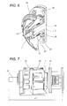
- the device according to the invention (see Figure 4) with all the characteristics set out above, remains contained in the same housing normally provided for mounting the hollow sleeve destined to house the shaft of a standard electric motor, and hence a reducer according to the invention has a total length L lesser than the length L1 of current reducer and joint assemblies (see Figure 4).
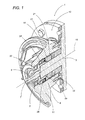
- the device according to the invention is globally indicated with the number 1.
- the device 1 comprises a bushing 2 able to be engaged without play to a shaft motor 3, in such a way as to be integral therewith under operative conditions.
- the bushing 2 as Figure 2 shows, has an inner surface 2a with a shape that is complementary to that of the drive shaft 3.
- the inner surface 2a has a coupling seat 4, for instance a seat for a tab, able to house a corresponding expansion, or a corresponding tab (not shown) of the drive shaft 3 which prevents, under operative conditions, the occurrence of relative rotations of the shaft 3 with respect to the bushing 2.
- the device further comprises a sleeve 5 and means 6 for connecting the bushing 2 to the sleeve 5.
- the sleeve 5 is operatively associated to a speed reducer, not shown in the drawings, which may be of any known kind.
- the speed reducer comprises a plurality of gears moved by a driving shaft which is engaged by interference inside the sleeve 5.
- the same device 1 comprises a pinion 7, shown in Figure 2 and only partially in Figure 1, which, in addition to the toothing 8, has a pivot pin 9 associated by fixed joint to the sleeve 5.
- the pinion 7 directly enmeshes a wheel of a speed reducer.
- the bushing 2, the sleeve 5 and the means 6 for connecting the bushing 2 to the sleeve 5 are mounted inside a housing compartment, indicated with the number 10 in figure 2, obtained in a frame 11.
- the housing compartment 10 is constituted by a through, cylindrical opening obtained in the frame 11; the bushing 2 and the sleeve 5 are mounted coaxially along the axis of development of said opening.
- a flange 12 is connected to the frame 11 to allow mounting the device on a motor (not shown), typically of the electric type, by means of a plurality of bolts 13.
- the means 6 for connecting the bushing 2 to the sleeve 5 comprise an elastic joint 14 active between the sleeve 5 and the bushing 2.
- the elastic joint 14 comprises a rigid ring 15 positioned between the sleeve 5 and the bushing 2 and coaxial to both.
- the ring 15 is associated, by fixed joint, to the sleeve 5; in detail, said connection is obtained by inserting a portion 5a of the sleeve inside the ring 15 in such a way as to bring a pair of planar abutment surfaces 16 of the ring 15 to bear against a pair of planar surfaces 17 of the sleeve 5.
- the ring 15 also has a plurality of connecting teeth 18 which develop towards the bushing 2 in a direction parallel to the axis 19 of the ring 15.
- the bushing 2 has a plurality of driving teeth 20 developing in the direction of the axis of the bushing 2, which coincides with the axis 19 of the ring 15.
- the elastic joint 14 lastly comprises a circular band 21, preferably made of elastomeric material, coaxial to the ring 15 and having a plurality of elastic inserts 22, typically made of the same material as the band 21.
- the elastic joint 14 and the bushing 2 are mounted in such a way that the aforesaid connecting teeth 18 are positioned between the driving teeth 20.
- Each of the elastic inserts 22 is then inserted between a connecting tooth 18 and a driving tooth 20, thereby achieving an elastic connection between the bushing 2 and the rigid ring 15.
- the device further comprise a first and a second bearing 23, 24 for mounting the sleeve 5 in rotary fashion on the frame 11.
- a first and a second bearing 23, 24 for mounting the sleeve 5 in rotary fashion on the frame 11.
- an elastic safety ring 25 and a sealing ring 26 are lastly positioned.
- connection between the bushing 2 and the sleeve 5 is obtained in an alternative manner, as shown in Figure 3.
- the bushing 2 has a plurality of engaging expansions 27, each of which develops along a circumference arc having its centre on the axis 19.
- Said engaging expansions 27 are housed in respective seats 28 obtained in the sleeve 5.
- the elastic joint 14 comprises a support ring 29 and a plurality of elastic inserts 30 positioned between the seats 28 and the engaging expansions 27.
- a device of the kind described above can advantageously integrated in a speed reducer 31 for electric motors 3, as shown in Figure 4.
- the frame 11 is mounted directly on the box body 32 which encloses the gears of the reducer.
- the drive shaft 3, not shown in Figure 4 is inserted into the bushing 2, as described above.
- the rotation of the drive shaft is transmitted by the means 6 to the sleeve 5 and hence to the pinion 7.
- the latter enmeshes at least one of the gear wheels which, typically, are present inside the reducer to move a driven shaft, indicated with number 33 in Figure 4, at a smaller number of rotations than the drive shaft 3.
- the present invention achieves important advantages.
- the illustrated solution allows to obtain devices constituted by components whose geometries are only minimally dependent on the type of motor or speed reducer with which the device is to be used.
- the sleeve 5, the frame 11 and all the means 6 for connecting the sleeve 5 to the bushing 2 can be made in a standardised manner, independent of the usage whereto the device is destined.
- These universal components can be mutually connected during the pre-assembly of the device to obtain a standard assembly whereto are associated, only subsequently, the components that depend on the motor, i.e. the bushing 2 and the flange 12, and those that depend on the speed reducer, like the pinion 7.
- the invention allows considerably to reduce the costs linked to the production of the device in question. From the mechanical viewpoint, the invention has the further advantage of being easily disassembled, even after a prolonged usage.
- the means 6 for connecting the bushing 2 to the sleeve 5 make the connection between the drive shaft 3 and the speed reducer partially elastic. This prevents the formation, between the drive shaft 3 and the sleeve 5, of micro-welds which would make it very difficult to separate the two bodies when, for instance, maintenance operations are to be performed.
- This kind of connection also allows slight offsets between the axis of the motor shaft and the bushing of the reducer, so that it is possible to obtain couplings with greater degrees of freedom between the motor and the speed reducer.
- the same characteristic of elasticity of the elements 22 or 30 between the drive shaft 3 and the sleeve 5 further allows the device to lower the vibration level in the reducer during its operation. This entails a better transmission of the motion from the drive shaft to the speed reducer, a limited wear of the components involved in said transmission, a drastic decrease in the noisiness of the device, a reduced conduction of the heat generated by the motor towards the reducer and a containment of the dimensions of the motor-reducer set with standard electrical coupling to a reducer.
Landscapes
- Engineering & Computer Science (AREA)
- General Engineering & Computer Science (AREA)
- Mechanical Engineering (AREA)
- Connection Of Motors, Electrical Generators, Mechanical Devices, And The Like (AREA)
- Replacement Of Web Rolls (AREA)
- Shafts, Cranks, Connecting Bars, And Related Bearings (AREA)
- Unwinding Webs (AREA)
Applications Claiming Priority (2)
| Application Number | Priority Date | Filing Date | Title |
|---|---|---|---|
| IT2000BO000709A ITBO20000709A1 (it) | 2000-12-05 | 2000-12-05 | Dispositivo di collegamento fra un albero e un riduttore di velocita' |
| ITBO000709 | 2000-12-05 |
Publications (2)
| Publication Number | Publication Date |
|---|---|
| EP1213501A2 true EP1213501A2 (de) | 2002-06-12 |
| EP1213501A3 EP1213501A3 (de) | 2004-08-25 |
Family
ID=11438899
Family Applications (1)
| Application Number | Title | Priority Date | Filing Date |
|---|---|---|---|
| EP01128825A Withdrawn EP1213501A3 (de) | 2000-12-05 | 2001-12-04 | Verbindungsvorrichtung zwischen der Welle eines Motors und eines Untersetzungsgetriebes |
Country Status (2)
| Country | Link |
|---|---|
| EP (1) | EP1213501A3 (de) |
| IT (1) | ITBO20000709A1 (de) |
Family Cites Families (3)
| Publication number | Priority date | Publication date | Assignee | Title |
|---|---|---|---|---|
| US1904745A (en) * | 1929-11-21 | 1933-04-18 | Eclipse Aviat Corp | Yielding coupling |
| USRE33620E (en) * | 1987-02-09 | 1991-06-25 | Margaux, Inc. | Continuously variable capacity refrigeration system |
| JP2515645Y2 (ja) * | 1989-11-21 | 1996-10-30 | アスモ 株式会社 | 減速機付モ−タ |
-
2000
- 2000-12-05 IT IT2000BO000709A patent/ITBO20000709A1/it unknown
-
2001
- 2001-12-04 EP EP01128825A patent/EP1213501A3/de not_active Withdrawn
Non-Patent Citations (1)
| Title |
|---|
| None |
Also Published As
| Publication number | Publication date |
|---|---|
| ITBO20000709A1 (it) | 2002-06-05 |
| ITBO20000709A0 (it) | 2000-12-05 |
| EP1213501A3 (de) | 2004-08-25 |
Similar Documents
| Publication | Publication Date | Title |
|---|---|---|
| US6125717A (en) | Close-connected shaft adapter assembly, jack shaft assembly, and power transmission assembly using same | |
| US8096857B2 (en) | Power tool, in particular angle grinder | |
| US4026163A (en) | Double speed reducer unit assembly | |
| JPWO2002023065A1 (ja) | 減速機付きモータのシリーズ | |
| JPH0956091A (ja) | 永久磁石式回転電機 | |
| JPH10281235A (ja) | 動力伝達装置 | |
| CN110890809A (zh) | 齿轮马达 | |
| FR2832481A1 (fr) | Boite de vitesses comportant une unite formant palier, unite formant palier et procede pour sa realisation | |
| JP2000042829A (ja) | 手動電動工具 | |
| JPH1035560A (ja) | 自転車用発電機とその取り付け方法 | |
| US6817268B1 (en) | Power distribution transmission | |
| JP3530406B2 (ja) | 増減速装置 | |
| KR101088633B1 (ko) | 기어드 모터 및 로봇용 기어드 모터 | |
| JP2026083330A (ja) | 動力伝達装置 | |
| JP2000350416A (ja) | 片持ち軸回転電動機及びその輸送時保護装置 | |
| JP2011219185A (ja) | モータ、モータ内蔵ローラおよびローラコンベア装置 | |
| JP3967527B2 (ja) | 変速機の出力部構造及び搬送システムの駆動機構 | |
| JP4036359B2 (ja) | 電動式パワーステアリング装置 | |
| KR100856566B1 (ko) | 차량용 시트 이송 기어박스 | |
| KR200499160Y1 (ko) | 모터 커버 | |
| CN210397642U (zh) | 电器装置变速机构 | |
| CN216185440U (zh) | 转向器动力组件及动力系统 | |
| KR100481291B1 (ko) | 이륜 자동차용 동력전달 시스템의 기어 소음 저감장치 | |
| JPH0649088Y2 (ja) | 回転計発電機付き回転電機 | |
| JP4759833B2 (ja) | 減速機一体型原動機 |
Legal Events
| Date | Code | Title | Description |
|---|---|---|---|
| PUAI | Public reference made under article 153(3) epc to a published international application that has entered the european phase |
Free format text: ORIGINAL CODE: 0009012 |
|
| AK | Designated contracting states |
Kind code of ref document: A2 Designated state(s): AT BE CH CY DE DK ES FI FR GB GR IE IT LI LU MC NL PT SE TR |
|
| AX | Request for extension of the european patent |
Free format text: AL;LT;LV;MK;RO;SI |
|
| PUAL | Search report despatched |
Free format text: ORIGINAL CODE: 0009013 |
|
| AK | Designated contracting states |
Kind code of ref document: A3 Designated state(s): AT BE CH CY DE DK ES FI FR GB GR IE IT LI LU MC NL PT SE TR |
|
| AX | Request for extension of the european patent |
Extension state: AL LT LV MK RO SI |
|
| AKX | Designation fees paid | ||
| REG | Reference to a national code |
Ref country code: DE Ref legal event code: 8566 |
|
| STAA | Information on the status of an ep patent application or granted ep patent |
Free format text: STATUS: THE APPLICATION IS DEEMED TO BE WITHDRAWN |
|
| 18D | Application deemed to be withdrawn |
Effective date: 20050226 |